2APA9-CMWG31BIMILAB Smart Hub
Shanghai Imilab Technology Co.,Ltd.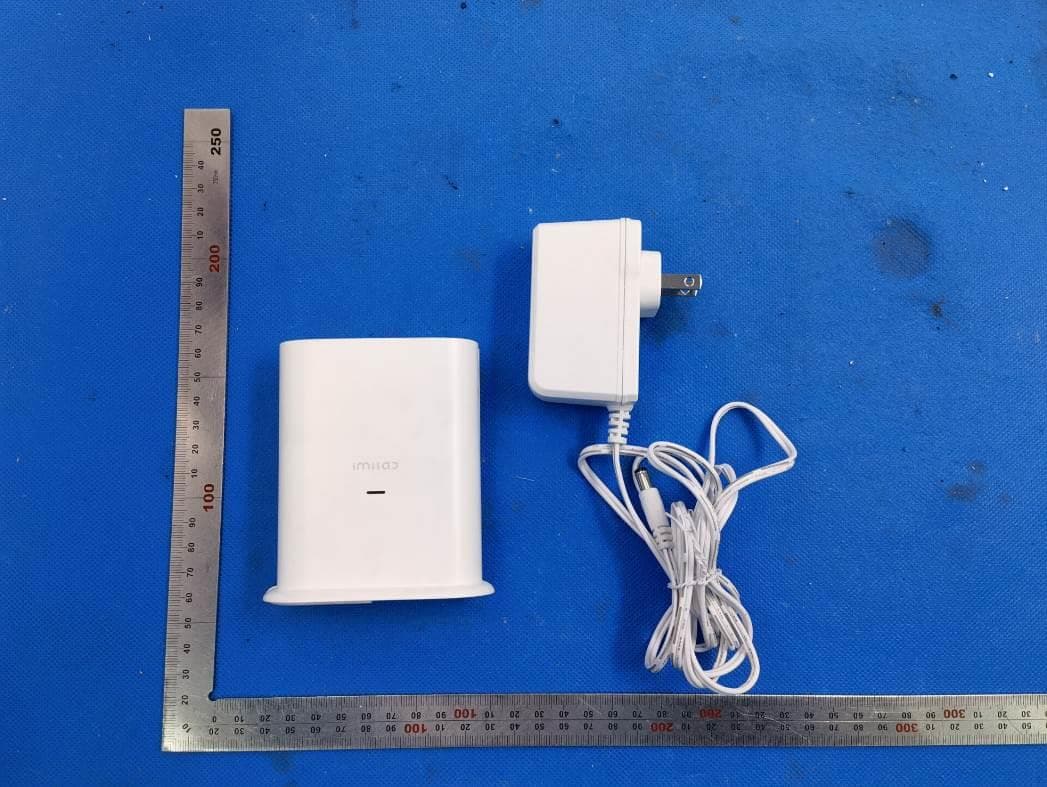
Click to zoom
Application Details
- Equipment Class
- DTS - Digital Transmission System
- Date of Grant
- May 12, 2021
- Application Purpose
- Original Equipment
- Date of Application
- May 12, 2021
- Equipment Note
- IMILAB Smart Hub
- Frequency Range
- 2412.00000000 - 2462.00000000
- Country
- China
Documents & Files
Document Text
Text extracted from the exhibit documents filed with the FCC. Open a document above to read the original.
Users Manual
7-10 ft (2-3 m) Up to 26 ft (8 m) CONTENTS English01-18 00-00Deutsche 00-00Español 00-00Italiano 00-00Français 00-00Pусский All products bearing this symbol are waste electrical and electronic equipment (WEEE as in directive 2012/ 19/EU) which should not be mixed with unsorted household waste. Instead, you should protect human health and the environment by handing over your waste equi pment to a designated collection point for the recycling of waste electrical and electronic equipment, appointed by the government or local authorities. Correct disposal and recycling will help prevent potential negative consequences to the environment and human health. Please contact the installer WEEE Information Hereby, Shanghai Imilab Technology Co., Ltd. declares that the radio equipment type IMILAB EC4 is in compliance with Directive 2014/53/EU. Hereby, Shanghai Imilab Technology Co., Ltd. declares that the radio equipment type IMILAB Smart Hub is in compliance with Directive 2014/53/EU. WEEE Information Connecting the hub 1.Use the ethernet cable provided to connect the hub to your home router. 2.Power on the hub. 3.The Status LED indicator turns solid orange when base Hub is ready for setup. SYNC USB Power Reset Ethernet Status LED EN-04 FCC Statement Changes or modifications not expressly approved by the party responsible for compliance could void the user's authority to operate the equipment. This device complies with Part 15 of the FCC Rules. Operation is subject to the following two conditions: (1) This device may not cause harmful interference, and (2) This device must accept any interference received, including interference that may cause undesired operation. Note: This equipment has been tested and found to comply with the limits for a Class B digital device, pursuant to Part 15 of the FCC Rules. These limits are designed to provide reasonable protection against harmful interference in a residential installation. This equipment generates, uses, and can radiate radio frequency energy, and if not installed and used in accordance with the instructions, may cause harmful interference to radio communications. However, there is no guarantee that interference will not occur in a particular installation. If this equipment does cause harmful interference to radio or television reception, which can be determined by turning the equipment off and on, the user is encouraged to try to correct the interference by one or more of the following measures: -Reorient or relocate the receiving antenna. -Increase the separation between the equipment and receiver. -Connect the equipment into an outlet on a circuit different from that to which the receiver is connected. -Consult the dealer or an experienced radio/TV technician for help. FCC 20cm Statement: This equipment complies with FCC radiation exposure limits set forth for an uncontrolled environment. This equipment should be installed and operated with a minimum distance of 20cm between the radiator & your body. This transmitter must not be co-located or operating in conjunction with any other antenna or transmitter. Method 1 Method 2 5V USB Charger Charging the camera SYNC USB Power Reset Ethernet Specifications Safety statement Name: IMILAB EC4 Model: CMSXJ31A Resolution: 2560x1440 Aperture: F1.6 Power Input: 5 V 2 A Item Dimensions: 82 x 86.8 x 50 mm Operating Temperature: -20 °C ~ 50 °C FCC ID:2APA9-CMSXJ31A Name: IMILAB Smart Hub Model: CMWG31B Power Input: 12 V 1.5 A Item Dimensions: 89.2 x 38 x 101.3 mm Operating Temperature: -10 °C ~ 45 °C Expandable Memory: MicroSD card (up to 64 GB) Wireless Connectivity: Wi-Fi IEEE 802.11 b/g/n 2.4 GHz Wired Connection: A 10/100M Self-adaptive ethernet interface FCC ID:2APA9-CMWG31B EN-13 Mount the camera The camera can be mounted both indoors and outdoors. 1. Drill two holes on the wall by using the base of the IMILAB EC4 as a template. It is recommended that you mark the locations of the hole with a pencil before drilling. The diameter of each hole is approximately 6 mm, and the depth is approximately 30mm. 2. Insert the anchors into the holes. EN-07 Camera field of view Motion Detection Zone Mounting the camera Select height and location 1. Hang the camera 7-10 ft (2-3m) above the ground. This height maximizes the detection range of the motion sensor of the camera. Product overview Hub Camera Alarm USB Power Reset Ethernet Status LED Spotlight Lens Microphone Status LED Light sensor Motion sensor Mounting hole Speaker MicroSD Card Slot Speaker Reset Button Power Port Ethernet Port USB Charging Port Alarm SYNC Button USB Charging Port EN-11 Explanations for LEDS 网关Status LED Status 蓝色闪烁 橙色常亮 橙色闪烁 蓝色和橙色交替闪烁3次 长按Reset按键,保持5秒 至指示灯橙色常亮,松开按键 橙色闪烁 重置过程中,网关重新启动 重置成功,可以开始绑定 蓝色常亮 网络连接中/未连接网络状态 网络连接成功/已连接网络状态 等待与app绑定/与app绑定中 正在开机中/重置成功/正在OTA升级中 OTA升级失败 Status Setting up the system Download the app and set up the system 1. Download the Imilab Home APP from the app store (ios devices) or google play (Android devices). 2. Sign up for a imilab home account , then follow the onscreen instructions to complete the setup. EN-05EN-06 EN-15EN-16 Manufacturer: Shanghai Imilab Technology Co., Ltd. Address: Room 001A, Floor 11, Block 1, No. 588 Zixing Road, Minhang District, Shanghai, China For further information, please go to www.imilab.com. Support: [email protected] WARNING This product can expose you to chemical Bisphenol A (BPA) which is known to the state of California to cause reproductive. For more information, go www.P65Wamings. ca. gov. Pantone Cool Gray 11C、C:0 M:20 Y:100 K:0 EN-12 开关机 听到开机音乐,开机成功 听到关机音乐,关机成功 长按SYNC Button 2秒, 至指示灯蓝色常亮 长按SYNC Button 15秒, 至指示灯红色闪烁 长按SYNC Button 8秒, 至指示灯蓝色闪烁,松开按键 使用USB充电线/太阳能板 充电,红色闪烁3次 绿色常亮 蓝色闪烁 蓝色常亮5秒后熄灭 蓝色和橙色交替闪烁3次 开始充电 充满电 开始重置 (重置过程中,摄像机会重新启动) 重置成功 配对成功 配对失败 摄像机充电 摄像机重置 摄像头Status LED StatusStatus 橙色闪烁1次PIR侦测到有人 PIR持续侦测到有人橙色持续闪烁 PIR侦测 灵敏度调节 4. Match the bottom groove of the camera mounting base with the raised area on the base. Press down until the two surfaces are flush, then turn it in eit…
Text truncated - open the document above for the full version.
Cover Letter(s)
Shanghai Imilab Technology Co., Ltd. Room 001A, Floor 11, Block 1, No. 588 Zixing Road, Minhang District, Shanghai, China Office of Engineering Technology Federal Communications Commission 7435 Oakland Mills Road Columbia, MD 21046 USA Date: Mar. 03, 2021 Subject: Declaration Operating Channel Limitation FCC ID: 2APA9-CMWG31B To Whom it may concern, This device is acting as slave/client device under the control of a master. The operating channels in 802.11 b/g/n mode for this device marketed to the US are firmware limited to channel 1 ~ 11 (2412 ~ 2462 MHz). The end-user has no possibility to select any other operating channels. If you have any questions, please feel free to contact me. Thank you. Sincerely, Signatory Shanghai Imilab Technology Co., Ltd. Contact person: wang hesong Title: General Manager
Cover Letter(s)
Shanghai Imilab Technology Co., Ltd. Room 001A, Floor 11, Block 1, No. 588 Zixing Road, Minhang District, Shanghai, China Agent Authorization Company: Shanghai Imilab Technology Co., Ltd. Address: Room 001A, Floor 11, Block 1, No. 588 Zixing Road, Minhang District, Shanghai, China Product Name: IMILAB Smart Hub Model Number(s): CMWG31B Product Description: IMILAB Smart Hub We authorize MiCOM Labs Inc., 575 Boulder Court, Pleasanton, California 94566, USA, to act on our behalf on all matters concerning the certification of above named equipment. We declare that MiCOM Labs Inc. is allowed to forward all information related to the approval and certification of equipment to the regulatory agencies as required and to discuss any issues concerning the approval application. Any and all acts carried out by MiCOM Labs on our behalf shall have the same effect as acts of our own. Signature: Date: Mar. 03, 2021 Name: wang hesong Title: General Manager Company: Shanghai Imilab Technology Co., Ltd.
External Photos
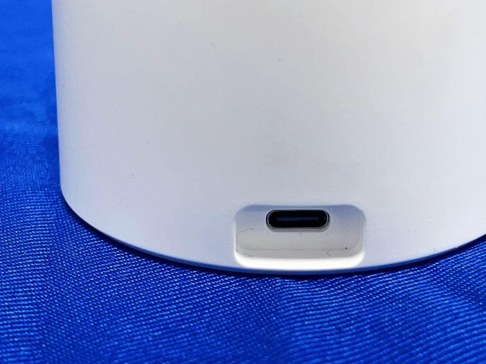
External Photos ALL VIEW OF EUT TOP VIEW OF EUT BOTTOM VIEW OF EUT FRONT VIEW OF EUT BACK VIEW OF EUT LEFT VIEW OF EUT RIGHT VIEW OF EUT VIEW OF EUT (PORT)-1 VIEW OF EUT (PORT)-2 VIEW OF ADAPTER
ID Label/Location Info
SN: X031B030000001 Made in China IMILAB Smart Hub Model: CMWG31B Power Input: 12 V 1.5 A FCC ID:2APA9-CMWG31B Shanghai Imilab Technology Co., Ltd. Made in China IMILAB Smart Hub Model: CMWG31B Power Input: 12 V 1.5 A FCC ID:2APA9-CMWG31B Shanghai Imilab Technology Co., Ltd. 70.2 mm 19.8 mm
Internal Photos
Internal Photos OPEN VIEW OF EUT INTERNAL VIEW-1 OF EUT INTERNAL VIEW-2 OF EUT INTERNAL VIEW-3 OF EUT Antenna 1 INTERNAL VIEW-4 OF EUT INTERNAL VIEW-5 OF EUT Antenna 2 INTERNAL VIEW-6 OF EUT
RF Exposure Info
RF EXPOSURE EVALUATION 1. PRODUCT INFORMATION Product Description IMILAB Smart Hub Model Name CMWG31B FCC ID 2APA9-CMWG31B 2. EVALUATION METHOD AND LIMIT Human exposure to RF emissions from mobile devices (47 CFR §2.1091) may be evaluated based on the MPE limits adopted by the FCC for electric and magnetic field strength and/or power density, as appropriate, since exposures are assumed to occur at distances of 20 cm or more from persons. LIMITS FOR GENERAL POPULATION / UNCONTROLLED EXPOSURE Frequency Range (MHz) E-field Strength (E) (V/m) Magnetic Field Strength (H) (A/m) Power Density (S) (mW/cm 2 ) Averaging Time |E| 2 , |H| 2 or S (Minutes) 0.3 -- 1.34 614 1.63 (100)* 30 1.34 -- 30 824/f 2.19/f (180/f 2 )* 30 30 -- 300 27.5 0.073 0.2 30 300 -- 1500 -- -- f/1500 30 1500 -- 100,000 -- -- 1.0 30 *Note: 1. f= Frequency in MHz * Plane-wave Equivalent Power Density 2. The averaging time for General Population/Uncontrolled exposure to fixed transmitters is not applicable for mobile and portable transmitters. See 47 CFR §§2.1091 and 2.1093 on source-based time-averaging requirement for mobile and portable transmitters. S=PG/4πR² Where: S=power density P=power input to antenna G=power gain of the antenna in the direction of interest relative to an isotropic radiator R=distance to the center of radiation of the antenna CALCULATION A minimum test separation distance ≥ 20 cm is required between the antenna and radiating structures of the device and nearby persons to apply mobile device exposure limits. The distance must be at least 20 cm and fully supported by the operating and installation configurations of the transmitter and its antenna(s), according to the source-based time-averaged maximum power requirements of § 2.1091(d)(2). In cases where cable losses or other attenuations are applied to determine compliance, the most conservative operating configurations and exposure conditions must be evaluated. 2.4G WIFI Antenna Gain=1.9dBi (Numeric 1.55), π=3.14 Note: 1. Only the worst case recorded. 3. conclusion Compliance the RF exposure requirement Frequency Output Power Output Power Power Density Power Density Limit MHz dBm mW mW/cm 2 mW/cm 2 2437 18.47 70.31 0.0217 1
Test Report
Page 1 of 87 Report No.: AGC05877210108FE05 FCC ID : 2APA9-CMWG31B APPLICATION PURPOSE : Original Equipment PRODUCT DESIGNATION : IMILAB Smart Hub BRAND NAME : N/A MODEL NAME : CMWG31B APPLICANT : Shanghai Imilab Technology Co., Ltd. DATE OF ISSUE : Mar. 02, 2021 STANDARD(S) TEST PROCEDURE(S) : FCC Part 15.247 REPORT VERSION : V1.0 Attestation of Global Compliance (Shenzhen) Co., Ltd FCC Test Report Report No.: AGC05877210108FE05 Page 2 of 87 EPORT REVISE RECORD Report Version Revise Time Issued Date Valid Version Notes V1.0 / Mar. 02, 2021 Valid Initial Release Report No.: AGC05877210108FE05 Page 3 of 87 TABLE OF CONTENTS 1. VERIFICATION OF CONFORMITY .................................................................................................................. 5 2. GENERAL INFORMATION .............................................................................................................................. 6 2.1. PRODUCT DESCRIPTION ........................................................................................................................ 6 2.2. TABLE OF CARRIER FREQUENCYS ....................................................................................................... 6 2.3. IEEE 802.11N MODULATION SCHEME .................................................................................................... 7 2.4. RELATED SUBMITTAL(S) / GRANT (S) .................................................................................................... 7 2.5. TEST METHODOLOGY ............................................................................................................................. 7 2.6. SPECIAL ACCESSORIES ......................................................................................................................... 7 2.7. EQUIPMENT MODIFICATIONS ................................................................................................................. 7 2.8. ANTENNA REQUIREMENT....................................................................................................................... 8 3. MEASUREMENT UNCERTAINTY ................................................................................................................... 9 4. DESCRIPTION OF TEST MODES ................................................................................................................. 10 5. SYSTEM TEST CONFIGURATION ................................................................................................................ 11 5.1. CONFIGURATION OF EUT SYSTEM ...................................................................................................... 11 5.2. EQUIPMENT USED IN EUT SYSTEM ..................................................................................................... 11 5.3. SUMMARY OF TEST RESULTS .............................................................................................................. 11 6. TEST FACILITY .............................................................................................................................................. 12 7. OUTPUT POWER ........................................................................................................................................... 13 7.1. MEASUREMENT PROCEDURE ............................................................................................................. 13 7.2. TEST SET-UP (BLOCK DIAGRAM OF CONFIGURATION) .................................................................... 13 7.3. LIMITS AND MEASUREMENT RESULT .................................................................................................. 14 8. 6 DB BANDWIDTH ......................................................................................................................................... 16 8.1. MEASUREMENT PROCEDURE ............................................................................................................. 16 8.2. TEST SET-UP (BLOCK DIAGRAM OF CONFIGURATION) .................................................................... 16 8.3. LIMITS AND MEASUREMENT RESULTS ............................................................................................... 17 9. CONDUCTED SPURIOUS EMISSION........................................................................................................... 25 Report No.: AGC05877210108FE05 Page 4 of 87 9.1. MEASUREMENT PROCEDURE ............................................................................................................. 25 9.2. TEST SET-UP (BLOCK DIAGRAM OF CONFIGURATION) .................................................................... 25 9.3. MEASUREMENT EQUIPMENT USEDJN ................................................................................................ 25 9.4. LIMITS AND MEASUREMENT RESULT .................................................................................................. 25 10. MAXIMUM CONDUCTED OUTPUT POWER SPECTRAL DENSITY ........................................................ 43 10.1 MEASUREMENT PROCEDURE ............................................................................................................ 43 10.2 TEST SET-UP (BLOCK DIAGRAM OF CONFIGURATION) ................................................................... 43 10.3 MEASUREMENT EQUIPMENT USED ................................................................................................... 43 10.4 LIMITS AND MEASUREMENT RESULT ................................................................................................. 43 11. RADIATED EMISSION ................................................................................................................................. 51 11.1. MEASUREMENT PROCEDURE............................................................................................................ 57 11.2. TEST SETUP ...........................................................................................................…
Text truncated - open the document above for the full version.
Test Report
Report No.: AGC05877210108FE05 Page 51 of 87 802.11b TEST RESULT AT ANTENNA 2 TEST PLOT OF SPECTRAL DENSITY FOR LOW CHANNEL TEST PLOT OF SPECTRAL DENSITY FOR MIDDLE CHANNEL Report No.: AGC05877210108FE05 Page 52 of 87 TEST PLOT OF SPECTRAL DENSITY FOR HIGH CHANNEL 802.11g TEST RESULT AT Antenna 2 TEST PLOT OF SPECTRAL DENSITY FOR LOW CHANNEL Report No.: AGC05877210108FE05 Page 53 of 87 TEST PLOT OF SPECTRAL DENSITY FOR MIDDLE CHANNEL TEST PLOT OF SPECTRAL DENSITY FOR HIGH CHANNEL Report No.: AGC05877210108FE05 Page 54 of 87 802.11n 20 TEST RESULT AT Antenna 2 TEST PLOT OF SPECTRAL DENSITY FOR LOW CHANNEL TEST PLOT OF SPECTRAL DENSITY FOR MIDDLE CHANNEL Report No.: AGC05877210108FE05 Page 55 of 87 TEST PLOT OF SPECTRAL DENSITY FOR HIGH CHANNEL 802.11n 40 TEST RESULT AT Antenna 2 TEST PLOT OF SPECTRAL DENSITY FOR LOW CHANNEL Report No.: AGC05877210108FE05 Page 56 of 87 TEST PLOT OF SPECTRAL DENSITY FOR MIDDLE CHANNEL TEST PLOT OF SPECTRAL DENSITY FOR HIGH CHANNEL Report No.: AGC05877210108FE05 Page 57 of 87 11. RADIATED EMISSION 11.1. MEASUREMENT PROCEDURE 1. The EUT was placed on the top of the turntable 0.8 or 1.5 meter above ground. The phase center of the receiving antenna mounted on the top of a height-variable antenna tower was placed 3 meters far away from the turntable. 2. Power on the EUT and all the supporting units. The turntable was rotated by 360 degrees to determine the position of the highest radiation. 3. The height of the broadband receiving antenna was varied between one meter and four meters above ground to find the maximum emissions field strength of both horizontal and vertical polarization. 4. For each suspected emissions, the antenna tower was scan (from 1 M to 4 M) and then the turntable was rotated (from 0 degree to 360 degrees) to find the maximum reading. 5. Set the test-receiver system to Peak or CISPR quasi-peak Detect Function with specified bandwidth under Maximum Hold Mode. 6. For emissions above 1GHz, use 1MHz RBW and 3MHz VBW for peak reading. Place the measurement antenna away from each area of the EUT determined to be a source of emissions at the specified measurement distance, while keeping the measurement antenna aimed at the source of emissions at each frequency of significant emissions, with polarization oriented for maximum response. The measurement antenna may have to be higher or lower than the EUT, depending on the radiation pattern of the emission and staying aimed at the emission source for receiving the maximum signal. The final measurement antenna elevation shall be that which maximizes the emissions. The measurement antenna elevation for maximum emissions shall be restricted to a range of heights of from 1 m to 4 m above the ground or reference ground plane. 7. When the radiated emissions limits are expressed in terms of the average value of the emissions, and pulsed operation is employed, the measurement field strength shall be determined by averaging over one complete pulse train, including blanking intervals, as long as the pulse train does not exceed 0.1 seconds. As an alternative (provided the transmitter operates for longer than 0.1 seconds) or in cases where the pulse train exceeds 0.1 seconds, the measured field strength shall be determined from the average absolute voltage during a 0.1 second interval during which the field strength is at its maximum values. 8.If the emissions level of the EUT in peak mode was 3 dB lower than the average limit specified, then testing will be stopped and peak values of EUT will be reported, otherwise, the emissions which do not have 3 dB margin will be repeated one by one using the quasi-peak method for below 1GHz. 9. For testing above 1GHz, the emissions level of the EUT in peak mode was lower than average limit (that means the emissions level in peak mode also complies with the limit in average mode), then testing will be stopped and peak values of EUT will be reported, otherwise, the emissions will be measured in average mode again and reported. 10. In case the emission is lower than 30MHz, loop antenna has to be used for measurement and the recorded data should be QP measured by receiver. High - Low scan is not required in this case. Report No.: AGC05877210108FE05 Page 58 of 87 11.2. TEST SETUP Radiated Emission Test-Setup Frequency Below 30MHz RADIATED EMISSION TEST SETUP 30MHz-1000MHz RADIATED EMISSION TEST SETUP ABOVE 1000MHz Report No.: AGC05877210108FE05 Page 59 of 87 11.3. LIMITS AND MEASUREMENT RESULT 15.209(a) Limit in the below table has to be followed Frequencies (MHz) Field Strength (micorvolts/meter) Measurement Distance (meters) 0.009~0.490 2400/F(KHz) 300 0.490~1.705 24000/F(KHz) 30 1.705~30.0 30 30 30~88 100 3 88~216 150 3 216~960 200 3 Above 960 500 3 Note: All modes were tested For restricted band radiated emission, the test records reported below are the worst result compared to other modes. 11.4. TEST RESULT RADIATED EMISSION BELOW 30MHZ The amplitude of spurious emissions from 9kHz to 30MHz which are attenuated more than 20 dB below the permissible value need not be reported. Report No.: AGC05877210108FE05 Page 60 of 87 RADIATED EMISSION BELOW 1GHZ EUT IMILAB Smart Hub Model Name CMWG31B Temperature 21.8°C Relative Humidity 58% Pressure 960hPa Test Voltage Normal Voltage Test Mode 802.11b with date rate 1 2412MHZ Antenna Horizontal RESULT: PASS Report No.: AGC05877210108FE05 Page 61 of 87 EUT IMILAB Smart Hub Model Name CMWG31B Temperature 21.8°C Relative Humidity 58% Pressure 960hPa Test Voltage Normal Voltage Test Mode 802.11b with date rate 1 2412MHZ Antenna Vertical RESULT: PASS Note: 1. Factor=Antenna Factor + Cable loss, Margin=Measurement-Limit. 2. The “Factor” value can be calculated automatically by software of measurement system. 3. All test modes of antenna 1 and antenna 2 had been pre-tested. The 802.11b at low channel of antenna 1 is the worst case and recorded in the report. Report No.: AGC05877210108FE05 Page 62 of 87 RADIATED EMISSION ABOVE 1GHZ EUT IMILAB Smar…
Text truncated - open the document above for the full version.
Test Setup Photos
Test Setup Photos FCC RADIATED EMISSION TEST SETUP BELOW 1GHZ FCC RADIATED EMISSION TEST SETUP ABOVE 1GHZ CONDUCTED EMISSION TEST SETUP CONDUCTED TEST SETUP
Contact Information
Applicant
yan siyang
Technical Contact
Test Firm
Attestation of Global Compliance (Shenzhen) Co., LDoris Li
[email protected]+86-755-25234088
Technical Specifications
| # | Rule Parts | Frequency Range | Power Output |
|---|---|---|---|
| 1 | 15C | 2.41 GHz - 2.46 GHz | 273.50 mW |
Other Applications from Shanghai Imilab Technology Co.,Ltd.
2APA9-A331D
Aug 12, 2026WiFi Smart Camera
Equipment Class
DTS - Digital Transmission System2APA9-CMSXJ115A
Sep 03, 2024IMILAB EC6 Panorama
Equipment Class
DTS - Digital Transmission System
2APA9-CMSXJ56F
Nov 19, 2023IMILAB C21
Equipment Class
DTS - Digital Transmission System
2APA9-CMSXJ33B
Apr 28, 2022IMILAB Doorbell Hub
Equipment Class
DTS - Digital Transmission System
2APA9-CMSXJ33A
Apr 24, 2022IMILAB Video Doorbell
Equipment Class
DTS - Digital Transmission System