2APA9-IPC036AIMILAB C20
Shanghai Imilab Technology Co.,Ltd.
Click to zoom
Application Details
- Equipment Class
- DTS - Digital Transmission System
- Date of Grant
- Aug 05, 2020
- Application Purpose
- Original Equipment
- Date of Application
- Aug 05, 2020
- Equipment Note
- IMILAB C20
- Frequency Range
- 2412.00000000 - 2462.00000000
- Country
- China
Documents & Files
Document Text
Text extracted from the exhibit documents filed with the FCC. Open a document above to read the original.
Users Manual
Product Overview IMILAB C20 can be placed on a number of horizontal surfaces, such as a writing desk, dining table, and coffee table. It can also be mounted on the wall. Mounted IMILAB C20 on a Wall: 1. Drill two holes on the wall by using the base of the IMILAB C20 as a template. It is recommended that you mark the locations of the hole with a pencil before drilling. The diameter of each hole is approximately 6 mm, and the depth is approximately 30 mm. 2. Insert the two plastic anchors into the holes on the wall. 3. Make sure to position the base unit so that the arrow is pointing up. Secure the base unit in place by tightening the screws into the plastic anchors. 4. Matching the grooves on the bottom of the camera unit with the raised area on the base unit. Press down until the two surfaces are flush, then turn the camera unit in either direction to lock it in position. Package Contents: IMILAB C20 x 1, power adapter x 1, power cable x 1, wall mounting accessories pack x 1, user manual x 1 Read this manual carefully before use, and retain it for future reference. Installation Warning: To avoid any damages or injuries, the device must be securely fastened to the floor/wall as specified in the installation instructions. When mounting the security camera on a wall: Please note that the wall must be able to support at least triple the product's total weight. MicroSD Indicator Light Steady blue on: connected/device status is normal Flashing blue: network error Flashing orange rapidly: waiting for connection Flashing orange slowly: system upgrade in progress Installing a MicroSD Card Make sure that the power to IMILAB C20 is already disconnected. Adjust the camera lens upward until the MicroSD slot is revealed, then insert the MicroSD card into the slot (the side with contact points must be facing down). Note: Please turn off the IMILAB C20‘s power supply before inserting or removing the MicroSD card. Please use a genuine Micro SD card manufactured by a qualified supplier, with a reading/writing speed of no less than U1/Class 10. (Maximum support capacity is 256 GB) Restore Factory Settings Press and hold the reset hole with fine needle,then you can hear the “reset succeed” voice. Data stored on the MicroSD card is not deleted. IMILAB C20 User Manual Install IMI Home App Connect with IMI Home app. This product works with IMI Home app. Control your device with IMI Home app. Scan the QR code to download and install the app. You will be directed to the connection setup page if the app is installed already. Or search “IMI Home” in the app store to download and install it. Open IMI Home app, tap “+” on the upper right, and then follow prompts to add your device. Note: The version of the app might have been updated, please follow the instructions based on the current app version. Add Device 1. If the indicator light is flashing orange, that means the device is activated successfully. If you do not see a flashing orangelight, please reset the device. 2. Once the IMILAB C20 is turned on, please do not attempt to rotate its head by force. If the camera position is incorrect, adjustments can be made through the app. Product Instructions Turning the Device On IMILAB C20 will automatically activate once the power cable is inserted into the Micro-USB charging port. Manufacturer: Shanghai Imilab Technology Co., Ltd. (a Mi Ecosystem Company) Address: Room 001A, Floor 11, Block 1, No. 588 Zixing Road, Minhang District, Shanghai, China For further information, please go to www.imilab.com. Support: [email protected] For Business: [email protected] Specifications Name: IMILAB C20 Model: CMSXJ36A Net Weight: 259g Lens Angle: 115° Resolution: 1920 x 1080 Power input: 5 V 2 A Expandable Memory: MicroSD card (up to 256GB) Dimensions: 108 mm x 75 mm x 75 mm Operating Temperature: -10 °C to 40 °C Compatible With: Android 4.4 or iOS 9.0 or above Wireless Connectivity: Wi-Fi IEEE 802.11 b/g/n 2.4GHz Reset Open IMI Home app, tap “+” on the upper right. Tap”[-]”and scan the QR code under the device by you phone, then you can follow the steps to add your device. Open IMI Home app, tap “+” on the upper right. Tap”IMILAB C20”and then you can follow the steps to add your device. WEEE Information EU Declaration of Conformity Hereby, Shanghai Imilab Technology Co., Ltd. declares that the radio equipment type IMILAB C20 is in compliance with Directive 2014/53/EU. The full text of the EU declaration of conformity is available at the following internet address: http://www.mi.com/global/service/support/declaration.html All products bearing this symbol are waste electrical and electronic equipment (WEEE as in directive 2012/19/EU) which should not be mixed with unsorted household waste. Instead, you should protect human health and the environment by handing over your waste equipment to a designated collection point for the recycling of waste electrical and electronic equipment, appointed by the government or local authorities. Correct disposal and recycling will help prevent potential negative consequences to the environment and human health. Please contact the installer or local authorities for more information about the location as well as terms and conditions of such collection points. MicroSD Slot (Can be revealed by pushing the lens upward) Lens Status indicator Loudspeaker Micro-USB Charging port MIC Reset Hole Front View Rear View Reset Camera IMILAB Home Security Cam... IMILAB Home Security Cam... Please enter the device name to... Changes or modifications not expressly approved by the party responsible for compliance could void the user's authority to operate the equipment. This device co mplies with Part 15 of the FCC Rules. Operation is subject to the following two conditions: (1) This device may not cause harmful inte rference, and (2) This device must accept any interference received, including interference that may cause undesired operation. Note: This equipment has been tested and found to comply with the limi…
Text truncated - open the document above for the full version.
Cover Letter(s)
QA-FR-170-B Company: Shanghai Imilab Technology Co.,Ltd. Add: Room 001A, Floor 11, Block 1, No. 588 Zixing Road, Minhang District, Shanghai, China Tel: 021-61890898 Fax: 021-64088898 FCC Authorization Date: 2020-06-28 FEDERAL COMMUNICATIONS COMMISSION Authorization and Evaluation Division 7435 Oakland Mills Road Columbia, MD 21046 Subject: Agent Authorization To whom it may concern: We, Shanghai Imilab Technology Co.,Ltd., the undersigned, Hereby authorizes Bay Area Compliance Laboratories Corporation to act on its behalf in all matters relating to application for Equipment authorization, including the signing of all documents relating to these matters. All acts carried out by Bay Area Compliance Laboratories Corp. on our behalf shall have the same effect as our own action. We, the undersigned, hereby certify that we are not subject to a denial of federal benefits, that includes FCC benefits, pursuant to Section 5301 of the Anti-Drug Abuse Act of 1988, 21 U.S.C. 862. This authorization is valid until further written notice from the applicant. Sincerely Yours, Signature: Typed or Printed Name: wang hesong Title: Manager
Cover Letter(s)
Company: Shanghai Imilab Techno logy Co.,Ltd. Add: Room 001A, Floor 11, Block 1, No. 588 Zixing Road, Minhang District, Shanghai, China Tel: 021-61890898 Fax: 021-6408889 8 E-mail: [email protected] FCC Confidential Authorization Date: 2020-06-28 FEDERAL COMMUNICATIONS COMMISSIONS Authorization and Evaluation Division 7435 Oakland Mills Road Columbia, MD 21046 Subject: Confidentiality Request regarding application for certification of FCC ID: 2APA9-IPC036A To: whom it may concern, In accordance with Sections 0.457 and 0.459 of the Commission’s Rules, Shanghai Imilab Technology Co.,Ltd. hereby requests long-term confidential treatment of i nformation accompanying this application as outlined below: Block Diagram Schematics Operation Description The above materials contain proprietary and confidential information not customarily released to the public. The public disclosure of these materials provides unjustified benefits to its competitors in the market. Sincerely Yours, Sig nature: Typed or Printed Name: wang hesong Title: Manager
External Photos
EXHIBIT A - EUT EXTERNAL PHOTOGRAPHS
Internal Photos
EXHIBIT B - EUT INTERNAL PHOTOGRAPHS Antenna
RF Exposure Info
Bay Area Compliance Laboratories Corp. (Kunshan) Report No.: RKSA200628001-00A FCC Part 15.247 Page 15 of 69 FCC §1.1310 & §2.1091 –MAXIMUM PERMISSIBLE EXPOSURE (MPE) Applicable Standard According to subpart §2.1091 and subpart §1.1310, systems operating under the provisions of this section shall be operated in a manner that ensures that the public is not exposed to radio frequency energy level in excess of the Commission’s guidelines. Limits for Maximum Permissible Exposure (MPE) (§1.1310, §2.1091) (B) Limits for General Population/Uncontrolled Exposure Frequency Range (MHz) Electric Field Strength (V/m) Magnetic Field Strength (A/m) Power Density (mW/cm 2 ) Averaging Time (minutes) 0.3-1.34 614 1.63 *(100) 30 1.34-30 824/f 2.19/f *(180/f²) 30 30-300 27.5 0.073 0.2 30 300-1500 / / f/1500 30 1500-100,000 / / 1.0 30 f = frequency in MHz; * = Plane-wave equivalent power density; According to §1.1310 and §2.1091 RF exposure is calculated. Calculated Formulary: Predication of MPE limit at a given distance S = PG/4πR² = power density (in appropriate units, e.g. mW/cm 2 ); P = power input to the antenna (in appropriate units, e.g., mW); G = power gain of the antenna in the direction of interest relative to an isotropic radiator, the power gain factor, is normally numeric gain; R = distance to the center of radiation of the antenna (appropriate units, e.g., cm); Calculated Data: Mode Frequency Range (MHz) Antenna Gain Target Output Power Evaluation Distance (cm) Power Density (mW/cm 2 ) MPE Limit (mW/cm 2 ) (dBi) (numeric)(dBm)(mW) 802.11b 2412~2462 1.0 1.26 19.5089.13 20 0.0223 1.0 802.11g 1.0 1.26 18.0063.10 20 0.0158 1.0 802.11 n-HT20 1.0 1.26 18.0063.10 20 0.0158 1.0 802.11 n-HT40 2422~2452 1.0 1.26 17.0050.12 20 0.0126 1.0 Note: The target output power was declared by the manufacturer. Conclusion: The device meets MPE at distance 20cm.
Test Report
FCC PART 15.247 TEST REPORT For Shanghai Imilab Technology Co.,Ltd. Room 001A, Floor 11, Block 1, No. 588 Zixing Road, Minhang District, Shanghai, China FCC ID: 2APA9-IPC036A Report Type: Original Report Product Type: IMILAB C20 Test Engineer: Chao Gao Re port Number: RKSA200628001-00A Re port Date: 2020-07-21 Reviewed B y: Oscar Ye EMC Manager Prepared By: Bay Area Compliance Laboratories Corp. (Kunshan) No.248 Chenghu Road, Kunshan, Jiangsu province, China Tel: +86-0512-86175000 Fax: +86-0512-88934268 www.baclcorp.com.cn Bay Area Compliance Laboratories Corp. (Kunshan) Report No.: RKSA200628001-00A FCC Part 15.247 Page 2 of 69 TABLE OF CONTENTS GENERAL INFORMATION ....................................................................................................................................... 4 PRODUCT DESCRIPTION FOR EQUIPMENT UNDER TEST (EUT) ..................................................................................... 4 OBJECTIVE ................................................................................................................................................................... 4 RELATED SUBMITTAL(S)/GRANT(S) ............................................................................................................................. 4 TEST METHODOLOGY .................................................................................................................................................. 5 MEASUREMENT UNCERTAINTY .................................................................................................................................... 6 TEST FACILITY ............................................................................................................................................................. 6 SYSTEM TEST CONFIGURATION .......................................................................................................................... 7 DESCRIPTION OF TEST CONFIGURATION ...................................................................................................................... 7 EQUIPMENT MODIFICATIONS ....................................................................................................................................... 7 EUT EXERCISE SOFTWARE .......................................................................................................................................... 7 SUPPORT EQUIPMENT LIST AND DETAILS .................................................................................................................. 11 EXTERNAL I/O CABLE ................................................................................................................................................ 11 BLOCK DIAGRAM OF TEST SETUP .............................................................................................................................. 11 SUMMARY OF TEST RESULTS ............................................................................................................................. 13 TEST EQUIPMENT LIST ......................................................................................................................................... 14 FCC §1.1310 & §2.1091 –MAXIMUM PERMISSIBLE EXPOSURE (MPE) ....................................................... 15 FCC §15.203 - ANTENNA REQUIREMENT ........................................................................................................... 16 APPLICABLE STANDARD ............................................................................................................................................ 16 ANTENNA CONNECTOR CONSTRUCTION .................................................................................................................... 16 FCC §15.207 (a) - AC LINE CONDUCTED EMISSIONS ...................................................................................... 17 APPLICABLE STANDARD ............................................................................................................................................ 17 EUT SETUP ................................................................................................................................................................ 17 EMI TEST RECEIVER SETUP ....................................................................................................................................... 17 TEST PROCEDURE ...................................................................................................................................................... 17 FACTOR & OVER LIMIT CALCULATION ...................................................................................................................... 18 TEST RESULTS SUMMARY .......................................................................................................................................... 18 TEST DATA ................................................................................................................................................................ 18 FCC §15.209, §15.205 & §15.247(d) - SPURIOUS EMISSIONS ............................................................................. 21 APPLICABLE STANDARD ............................................................................................................................................ 21 EUT SETUP ................................................................................................................................................................ 21 EMI TEST RECEIVER SETUP ....................................................................................................................................... 22 TEST PROCEDURE ...................................................................................................................................................... 22 CORRECTED AMPLITUDE & MARGIN CALCULATION .......................................................................…
Text truncated - open the document above for the full version.
Test Setup Photos
EXHIBIT C - TEST SETUP PHOTOGRAPHS Conducted Emissions (Front View) Conducted Emissions (Side View) Radiated Emissions (Below 1GHz) Radiated Emissions (Above 1GHz)
Contact Information
Applicant
yan siyang
Test Firm
Bay Area Compliance Laboratories Corp. (Kunshan)Mr. John Chan
[email protected]+86 0512 86175000
Technical Specifications
| # | Rule Parts | Frequency Range | Power Output |
|---|---|---|---|
| 1 | 15C | 2.41 GHz - 2.46 GHz | 81.00 mW |
Other Applications from Shanghai Imilab Technology Co.,Ltd.
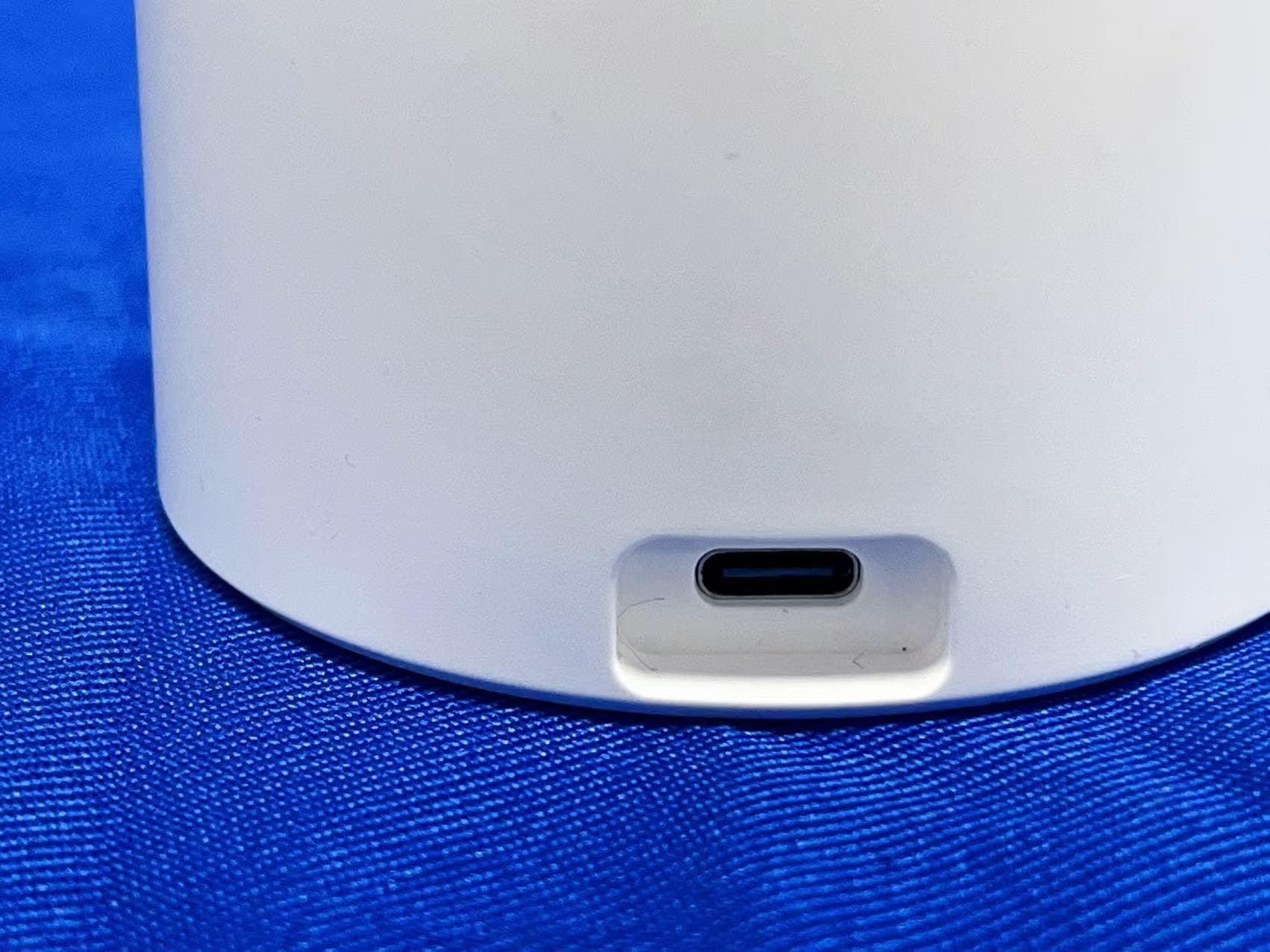
2APA9-A331D
Aug 12, 2026WiFi Smart Camera
Equipment Class
DTS - Digital Transmission System2APA9-CMSXJ115A
Sep 03, 2024IMILAB EC6 Panorama
Equipment Class
DTS - Digital Transmission System
2APA9-CMSXJ56F
Nov 19, 2023IMILAB C21
Equipment Class
DTS - Digital Transmission System
2APA9-CMSXJ33B
Apr 28, 2022IMILAB Doorbell Hub
Equipment Class
DTS - Digital Transmission System
2APA9-CMSXJ33A
Apr 24, 2022IMILAB Video Doorbell
Equipment Class
DTS - Digital Transmission System