2APQIIT-AF-SMTSmart Attic Fan Control
QC Manufacturing Inc.
Click to zoom
Application Details
- Equipment Class
- DSS - Part 15 Spread Spectrum Transmitter
- Date of Grant
- Jan 31, 2020
- Application Purpose
- Original Equipment
- Date of Application
- Jan 31, 2020
- Equipment Note
- Smart Attic Fan Control
- Frequency Range
- 2402.00000000 - 2480.00000000
- Company
- QC Manufacturing Inc.
- Country
- United States
Documents & Files
Document Text
Text extracted from the exhibit documents filed with the FCC. Open a document above to read the original.
Users Manual
IT-AF-SMT Smart Attic Fan Control Installation Guide Overview: This document summarizes introductions for operating hub IT-AF-SMT. The IT-AF-SMT can remotely control the QuietCool Attic Fans of QC Manufacturing Inc at up to three different speeds. Key Specifications: IT-AF-SMT (Hub): Voltage: 120V Frequency: 60Hz Motor load: 1HP, 735W (Max) Warning: - Disconnect power at the circuit breaker before installing or servicing - Use wires rated at least 105 o C – copper only - Installation/wiring must be in accordance with national and local code regulations - Keep the enclosure cover closed at all times when not servicing. - Cover all unused wires with a wire connector FCC Regulations: Supplier’s Declaration of Conformity Unique Identifier: Smart Attic Fan Control/IT-AF-SMT Responsible Party: QC Manufacturing Inc. 26040 Ynez Rd. Temecula CA 92591 Tel:951-325-6340 FCC Compliance Statement This device complies with Part 15 of the FCC Rules. Operation is subject to the following two conditions:(1) this device may not cause harmful interference, and (2) this device must accept any interference received, including interference that may cause undesired operation. Caution: The user is cautioned that changes or modifications not expressly approved by the party responsible for compliance could void the user's authority to operate the equipment. Note: This equipment has been tested and found to comply with the limits for a Class B digital device, pursuant to part 15 of the FCC Rules. These limits are designed to provide reasonable protection against harmful interference in a residential installation. This equipment generates uses and can radiate radio frequency energy and, if not installed and used in accordance with the instructions, may cause harmful interference to radio communications. However, there is no guarantee that interference will not occur in a particular installation. If this equipment does cause harmful interference to radio or television reception, which can be determined by turning the equipment off and on, the user is encouraged to try to correct the interference by one or more of the following measures: - Reorient or relocate the receiving antenna. - Increase the separation between the equipment and receiver. - Connect the equipment into an outlet on a circuit different from that to which the receiver is connected. - Consult the dealer or an experienced radio/TV technician for help. FCC RF Radiation Exposure Statement: This equipment complies with FCC radiation exposure limits set forth for an uncontrolled environment. This equipment should be installed and operated with a minimum distance of 20cm between the radiator and any part of your body. Rev 2.0 Page 1 of 2 Fig. 1 Dip Switch for Fan Speed Configuration 1 speed fan: Dial 1 to "ON”; and 2 speed fan: Dial 2 to "ON”; and 3 speed fan: Dial 3 to "ON” White wire ACN Black wire ACL Red wire Low speed wire Yellow wire Medium speed wire Blue wire High speed wire Fig. 2 Connection Wires of IT-AF-SMT Input wires: Black: Line voltage, ACL White: Neutral, ACN Output wires: Red: Low speed Yellow: Medium speed Blue: High speed Once wiring is completed, close the hub cover and tighten the screw. Operation: Power on the Hub: Switch on power to the hub, the Power indicator on the hub will be on, and other three indicators will stay off. Press the “Test” button to change fan speed, the fan will run in the following cycles: 1 speed fan: on -> off -> on -> off, 2 speed fan: high speed -> low speed -> off -> high speed -> low speed -> off, 3 speed fan: high speed -> medium speed -> low speed -> off -> high speed -> medium speed -> low speed -> off. And, the Test indicator will blink as follows: Low speed on: the speed LED will blink once every 2 seconds, Medium speed on: the speed LED will blink twice every 2 seconds, and High speed on: the speed LED will blink three times every 2 seconds. Notes: If the corresponding DIP switch of the fan is configured incorrectly, all the indicators on the hub will keep blinking when the hub is powered on. Please switch off power and re-configure the DIP switch correctly. Then try again. Rev 2.0 Page 2 of 2 Installation: IT-AF-SMT (Hub): (Please switch off main power before wiring. The installation should be done by qualified personnel only) The hub (with a curved bottom) should be attached to the cylindrical fan housing and is wired to the fan motor. Remove the screw that holds down the hub cover and flip it up. Once the cover is open, a three digit dip switch is available for fan speed configuration, as shown in Fig. 1.
Cover Letter(s)
QC Manufacturing Inc. DATE: 2019-9-18 Federal Communications Commission 7 435 Oakland Mills Road Columbia, MD 21046 Request for Short-Term Confidentiality Company name: QC Manufacturing Inc. FCC ID: 2APQIIT-AF-SMT FCC Part 15 Certification Pursuant to S ections 0.457 and 0.459 of the commission rules, and in accordance with the FCC Public notice dated June 15, 2004 (DA 04-1705), we hereby request short-term confidentiality for the following items prior to marketing the device.: (1)Test Setup Photos (2)External Photos (3)Internal Photos (4)User Manual The applicant requests the exhibits selected above as short term confidential be withheld from public view for a period of 180 days from the date of the Grant of Equipment Authorization and prior to marketing. This is to avoid premature release of sensitive information prior to marketing or release of the product to the public. Sincerely,
External Photos
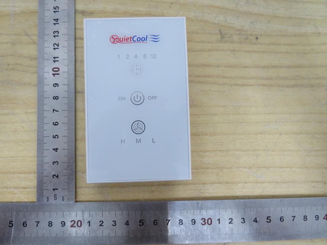
Appendix I External Photographs Page 2 of 3 UL Verification Services (Guangzhou) Co., Ltd, Song Shan Lake Branch This report shall not be reproduced except in full, without the written approval of UL Verification Services (Guangzhou) Co., Ltd, Song Shan Lake Branch. . Detail View of EUT-1 Detail View of EUT-2 Page 3 of 3 UL Verification Services (Guangzhou) Co., Ltd, Song Shan Lake Branch This report shall not be reproduced except in full, without the written approval of UL Verification Services (Guangzhou) Co., Ltd, Song Shan Lake Branch. . Detail View of EUT-3 Detail View of EUT-4
Internal Photos
Appendix II Internal Photographs Page 2 of 5 UL Verification Services (Guangzhou) Co., Ltd, Song Shan Lake Branch This report shall not be reproduced except in full, without the written approval of UL Verification Services (Guangzhou) Co., Ltd, Song Shan Lake Branch. . Open View of EUT-1 Open View of EUT-2 Internal View of EUT-1 Page 3 of 5 UL Verification Services (Guangzhou) Co., Ltd, Song Shan Lake Branch This report shall not be reproduced except in full, without the written approval of UL Verification Services (Guangzhou) Co., Ltd, Song Shan Lake Branch. . Internal View of EUT-2 Internal View of EUT-3 BT&WIFI Antenna Page 4 of 5 UL Verification Services (Guangzhou) Co., Ltd, Song Shan Lake Branch This report shall not be reproduced except in full, without the written approval of UL Verification Services (Guangzhou) Co., Ltd, Song Shan Lake Branch. . Internal View of EUT-4 BT&WIFI Model Page 5 of 5 UL Verification Services (Guangzhou) Co., Ltd, Song Shan Lake Branch This report shall not be reproduced except in full, without the written approval of UL Verification Services (Guangzhou) Co., Ltd, Song Shan Lake Branch. . Internal View of EUT-5
RF Exposure Info
The results reported herein have been performed in accordance with the laboratory’s terms of accreditation. This report shall not be reproduced except in full without the written approval of the Laboratory. The results in this report apply to the test sample(s) mentioned above at the time of the testing period only and are not to be used to indicate applicability to other similar products. This report does not imply that the product(s) has met the criteria for certification. FCC RF EXPOSURE REPORT For Smart Attic Fan Control MODEL NUMBER: IT-AF-SMT FCC ID: 2APQIIT-AF-SMT REPORT NUMBER: 4789100933.1-5 ISSUE DATE: December 06, 2019 Prepared for QC Manufacturing Inc. 26040 Ynez Rd. Temecula , CA 92591,USA Prepared by UL Verification Services (Guangzhou) Co., Ltd, Song Shan Lake Branch Building 10, Innovation Technology Park, No. 1, Li Bin Road, Song Shan Lake Hi-Tech Development Zone, Dongguan, People’s Republic of China Tel: +86 769-22038881 Fax: +86 769 33244054 Website: www.ul.com REPORT No.: 4789100933.1-5 Page 2 of 6 UL Verification Services (Guangzhou) Co., Ltd, Song Shan Lake Branch This report shall not be reproduced except in full, without the written approval of UL Verification Services (Guangzhou) Co., Ltd, Song Shan Lake Branch. TABLE OF CONTENTS 1. ATTESTATION OF TEST RESULTS .................................................................................... 3 2. TEST METHODOLOGY ........................................................................................................ 3 3. FACILITIES AND ACCREDITATION .................................................................................... 4 4. REQUIREMENT .................................................................................................................... 5 REPORT No.: 4789100933.1-5 Page 3 of 6 UL Verification Services (Guangzhou) Co., Ltd, Song Shan Lake Branch This report shall not be reproduced except in full, without the written approval of UL Verification Services (Guangzhou) Co., Ltd, Song Shan Lake Branch. 1. ATTESTATION OF TEST RESULTS Applicant Information Company Name: QC Manufacturing Inc. Address: 26040 Ynez Rd. Temecula , CA 92591,USA Manufacturer Information Company Name: Shenzhen Asia Bright Industry Co.,Ltd. Address: Building 10, Asia Industrial Park, Gangtou, Bantian,Shenzhen, China EUT Description Product Name Smart Attic Fan Control Model Name IT-AF-SMT Sample Status Normal Sample ID 2571291 Sample Received date September 25, 2019 Date Tested November 22 ~ December 05, 2019 APPLICABLE STANDARDS STANDARD TEST RESULTS FCC 47CFR§2.1091 KDB-447498 D01 V06 PASS Prepared By: Checked By: Kebo Zhang Shawn Wen Engineer Project Associate Laboratory Leader Approved By: Stephen Guo Laboratory Manager REPORT No.: 4789100933.1-5 Page 4 of 6 UL Verification Services (Guangzhou) Co., Ltd, Song Shan Lake Branch This report shall not be reproduced except in full, without the written approval of UL Verification Services (Guangzhou) Co., Ltd, Song Shan Lake Branch. 2. TEST METHODOLOGY The tests documented in this report were performed in accordance with KDB 447498 D01 General RF Exposure Guidance v06. 3. FACILITIES AND ACCREDITATION Accreditation Certificate A2LA (Certificate No.: 4102.01) UL Verification Services (Guangzhou) Co., Ltd. Song Shan Lake Branch. has been assessed and proved to be in compliance with A2LA. FCC (FCC Designation No.: CN1187) UL Verification Services (Guangzhou) Co., Ltd. Song Shan Lake Branch. Has been recognized to perform compliance testing on equipment subject to the Commission's Delcaration of Conformity (DoC) and Certification rules ISED(Company No.: 21320) UL Verification Services (Guangzhou) Co., Ltd. Song Shan Lake Branch. has been registered and fully described in a report filed with Industry Canada. The Company Number is 21320. VCCI (Registration No.: G-20019, R-20004, C-20012 and T-20011) UL Verification Services (Guangzhou) Co., Ltd. Song Shan Lake Branch. has been assessed and proved to be in compliance with VCCI, the Membership No. is 3793. Facility Name: Chamber D, the VCCI registration No. is G-20019 and R-20004 Shielding Room B , the VCCI registration No. is C-20012 and T-20011 Note 1: All tests measurement facilities use to collect the measurement data are located at Building 10, Innovation Technology Park, Song Shan Lake Hi tech Development Zone, Dongguan, 523808, China Note 2: The test anechoic chamber in UL Verification Services (Guangzhou) Co., Ltd. Song Shan Lake Branch had been calibrated and compared to the open field sites and the test anechoic chamber is shown to be equivalent to or worst case from the open field site. Note 3: For below 30MHz, lab had performed measurements at test anechoic chamber and comparing to measurements obtained on an open field site. And these measurements below 30MHz had been correlated to measurements performed on an OFS. REPORT No.: 4789100933.1-5 Page 5 of 6 UL Verification Services (Guangzhou) Co., Ltd, Song Shan Lake Branch This report shall not be reproduced except in full, without the written approval of UL Verification Services (Guangzhou) Co., Ltd, Song Shan Lake Branch. 4. REQUIREMENT LIMIT Limits for General Population/Uncontrolled Exposure Limits for General Population/Uncontrolled Exposure Frequency Range (MHz) Electric Field Strength (E) (V/m) Magnetic Field Strength (H) (A/m) Power Density (S) (mW/cm 2 ) Averaging Time |E| 2 , |H| 2 or S (minutes) 0.3-1.34 614 1.63 (100)* 30 1.34-30 824/f 2.19/f (180/f2)* 30 30-300 27.5 0.073 0.2 30 300-1500 -- -- f/150 30 1500-100,000 -- -- 1.0 30 Note 1: f = frequency in MHz, * means Plane-wave equivalent power density Note 2: General population/uncontrolled exposures apply in situations in which the general public may be exposed, or in which persons that are exposed as a consequence of their employment may not be fully aware of the potential for exposure or cannot exercise control over their exposure. Note 3: The limit value 1.0mW/cm 2 is available for this EUT. MPE CALCU…
Text truncated - open the document above for the full version.
Test Report
The results reported herein have been performed in accordance with the laboratory’s terms of accreditation. This report shall not be reproduced except in full without the written approval of the Laboratory. The results in this report apply to the test sample(s) mentioned above at the time of the testing period only and are not to be used to indicate applicability to other similar products. This report does not imply that the product(s) has met the criteria for certification. CFR 47 FCC PART 15 SUBPART C CERTIFICATION TEST REPORT For Smart Attic Fan Control MODEL NUMBER: IT-AF-SMT FCC ID: 2APQIIT-AF-SMT REPORT NUMBER: 4789100933.1-3 ISSUE DATE: Jan. 21, 2020 Prepared for QC Manufacturing Inc. 26040 Ynez Rd. Temecula , CA 92591,USA Prepared by UL Verification Services (Guangzhou) Co., Ltd, Song Shan Lake Branch Building 10, Innovation Technology Park, No. 1, Li Bin Road, Song Shan Lake Hi-Tech Development Zone Dongguan, People’s Republic of China Tel: +86 769 22038881 Fax: +86 769 33244054 Website: www.ul.com REPORT No.: 4789100933.1-3 Page 2 of 99 UL Verification Services (Guangzhou) Co., Ltd, Song Shan Lake Branch FORM No.: 10-SL-F0035 This report shall not be reproduced except in full, without the written approval of UL Verification Services (Guangzhou) Co., Ltd, Song Shan Lake Branch. Revision History Rev. Issue Date Revisions Revised By V0 1/21/2020 Initial Issue REPORT No.: 4789100933.1-3 Page 3 of 99 UL Verification Services (Guangzhou) Co., Ltd, Song Shan Lake Branch FORM No.: 10-SL-F0035 This report shall not be reproduced except in full, without the written approval of UL Verification Services (Guangzhou) Co., Ltd, Song Shan Lake Branch. Summary of Test Results Clause Test Items FCC/ISED Rules Test Results 1 20dB Bandwidth FCC 15.247 (a) (1) Pass 2 Conducted Output Power FCC 15.247 (b) (1) Pass 3 Carrier Hopping Channel Separation FCC 15.247 (a) (1) Pass 4 Number of Hopping Frequency 15.247 (a) (1) III Pass 5 Time of Occupancy (Dwell Time) 15.247 (a) (1) III Pass 6 Conducted Bandedge FCC 15.247 (d) Pass 7 Radiated Bandedge and Spurious FCC 15.247 (d) FCC 15.209 FCC 15.205 Pass 8 Conducted Emission Test For AC Power Port FCC 15.207 Pass 9 Antenna Requirement FCC 15.203 Pass Note: This test report is only published to and used by the applicant, and it is not for evidence purpose in China. REPORT No.: 4789100933.1-3 Page 4 of 99 UL Verification Services (Guangzhou) Co., Ltd, Song Shan Lake Branch FORM No.: 10-SL-F0035 This report shall not be reproduced except in full, without the written approval of UL Verification Services (Guangzhou) Co., Ltd, Song Shan Lake Branch. TABLE OF CONTENTS 1. ATTESTATION OF TEST RESULTS .................................................................................... 6 2. TEST METHODOLOGY ........................................................................................................ 7 3. FACILITIES AND ACCREDITATION .................................................................................... 7 4. CALIBRATION AND UNCERTAINTY .................................................................................. 8 4.1. MEASURING INSTRUMENT CALIBRATION ................................................................ 9 4.2. MEASUREMENT UNCERTAINTY ................................................................................. 8 5. EQUIPMENT UNDER TEST ................................................................................................. 9 5.1. DESCRIPTION OF EUT ................................................................................................. 9 5.2. MAXIMUM OUTPUT POWER ........................................................................................ 9 5.3. PACKET TYPE CONFIGURATION ................................................................................ 9 5.4. CHANNEL LIST ............................................................................................................ 10 5.5. TEST CHANNEL CONFIGURATION ........................................................................... 10 5.6. THE WORSE CASE POWER SETTING PARAMETER ............................................... 10 5.7. DESCRIPTION OF AVAILABLE ANTENNAS .............................................................. 11 5.8. WORST-CASE CONFIGURATIONS ............................................................................ 11 5.9. DESCRIPTION OF TEST SETUP ................................................................................ 12 6. MEASURING INSTRUMENT AND SOFTWARE USED ..................................................... 13 7. ANTENNA PORT TEST RESULTS .................................................................................... 15 7.1. ON TIME AND DUTY CYCLE ...................................................................................... 15 7.2. 20 dB OCCUPIED BANDWIDTH ................................................................................. 17 7.2.1. GFSK MODE ......................................................................................................... 18 7.2.2. 8DPSK MODE ....................................................................................................... 21 7.3. CONDUCTED OUTPUT POWER ................................................................................ 23 7.3.1. GFSK MODE ......................................................................................................... 24 7.3.2. 8DPSK MODE ....................................................................................................... 24 7.4. CARRIER HOPPING CHANNEL SEPARATION .......................................................... 25 7.4.1. GFSK MODE ......................................................................................................... 26 7.4.2. 8DPSK MODE ....................................................................................................... 27 7.5. NUMBER OF HOPPING FREQUENCY ....................................................................…
Text truncated - open the document above for the full version.
Test Setup Photos
Appendix II Setup Photographs RADIATED RF MEASUREMENT SETUP (ABOVE 1 GHz) MEASUREMENT POSITION MEASUREMENT POSITION (X axis) MEASUREMENT POSITION (Y axis) MEASUREMENT POSITION (Z axis) RADIATED RF MEASUREMENT SETUP (30MHz~1GHz) RADIATED RF MEASUREMENT SETUP (Below 30MHz) POWERLINE CONDUCTED EMISSIONS MEASUREMENT SETUP
Contact Information
Applicant
Jeff Whitehouse(Director of Purchasing)
Test Firm
UL Verification Services (Guangzhou) Co., Ltd.Stephen Guo
[email protected]+86 0769 33817120
Technical Specifications
| # | Rule Parts | Frequency Range | Power Output |
|---|---|---|---|
| 1 | 15C | 2.40 GHz - 2.48 GHz | 2.00 mW |
Other Applications from QC Manufacturing Inc.
2APQIITRFGLSWITCH01
Jun 27, 2023RF Glass Switch
Equipment Class
DSC - Part 15 Security/Remote Control Transmitter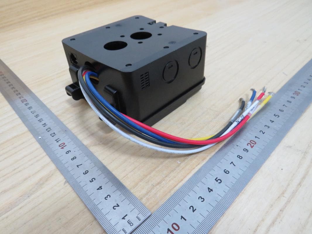
2APQIIT-AC-HUB-01
Jan 12, 2023Whole House Fan Hub
Equipment Class
DSC - Part 15 Security/Remote Control Transmitter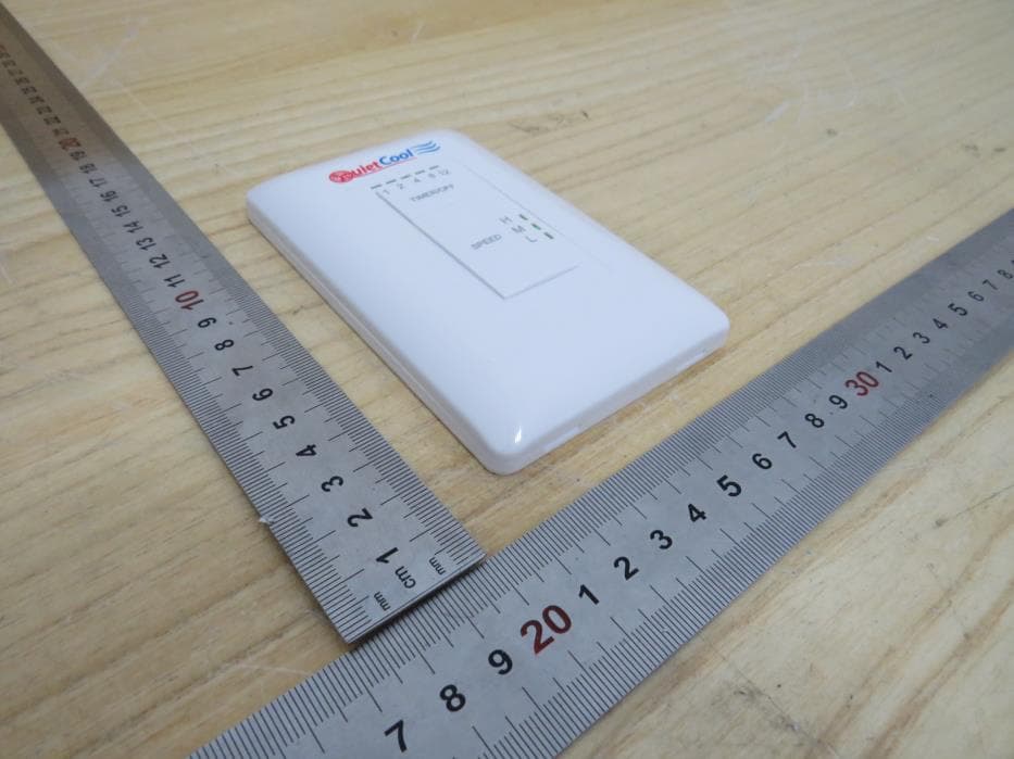
2APQIIT-RFSWITCH-02
Oct 01, 2022RF Switch
Equipment Class
DSC - Part 15 Security/Remote Control Transmitter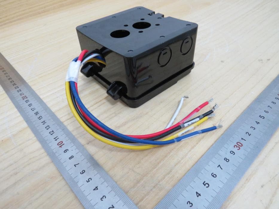
2APQIIT-RFHUB-02
Oct 01, 2022RF Hub
Equipment Class
DSR - Part 15 Remote Control/Security Device Transceiver