2APQIITRFGLSWITCH01RF Glass Switch
QC Manufacturing Inc.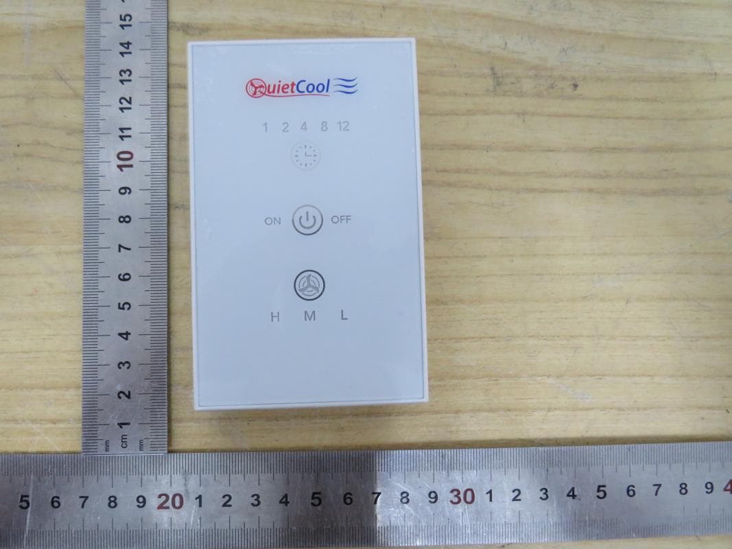
Click to zoom
Application Details
- Equipment Class
- DSC - Part 15 Security/Remote Control Transmitter
- Date of Grant
- Jun 27, 2023
- Application Purpose
- Original Equipment
- Date of Application
- Jun 27, 2023
- Equipment Note
- RF Glass Switch
- Frequency Range
- 433.92000000 - 433.92000000
- Company
- QC Manufacturing Inc.
- Country
- United States
Documents & Files
Document Text
Text extracted from the exhibit documents filed with the FCC. Open a document above to read the original.
Users Manual
DO NOT THROW AWAY! OWNER’S GUIDE CONTAINS IMPORTANT INFORMATION. LEAVE WITH HOMEOWNER OWNER’S GUIDE Wireless RF Control Kit IT-36003 ! 1-888-QUIETCOOL 2 GENERAL SAFETY INSTRUCTIONS 1. Read Instructions - All safety and operation instructions must be read. 2. Retain Instructions - The safety and operating instructions should be kept for future reference. 3. Heed Warnings - All warnings should be followed. 4. Follow Instructions - All installation and operating instructions should be followed. 5. Water – The QuietCool system should not be used near water. If you live in a very humid climate, be sure to cover your damper box with insulation to reduce condensation. 6. Heat - The QuietCool system should be situated away from heat sources. 7. Damage Requiring Service - Only qualified service personnel should service the QuietCool system. The user should not attempt to service the product. CONTENTS 1. SYSTEM OVERVIEW ..........................................3 1.1 Introduction ............................................3 1.2 Features ...............................................3 1.3 Key Specifications .......................................3 2. INSTALLATION ..............................................4 2.1 Installing the Hub ........................................4 2.2 Wiring the Hub. . . . . . . . . . . . . . . . . . . . . . . . . . . . . . . . . . . . . . . . . .4 2.3 Fan Hub LED Indicators ..................................9 2.4 Pairing the Wall Switch ..................................10 2.5 Finding a Location for the Wall Switch .....................10 2.6 Installing the Wall Switch ................................11 3. OPERATION ...............................................11 3.1 Operating the Wall Switch ...............................11 3.2 Frequently Asked Questions .............................12 RF WIRELESS CONTROL WARRANTY ............................14 INCLUDED IN THE BOX - IT-AC-HUB-01 Control Hub - IT-RFGLSSWITCH-01 RF Switch - QuietCool Owner’s Guide - (2) AAA batteries - Mounting screws and drywall anchors STOP! READ ALL INSTRUCTIONS IN THIS GUIDE BEFORE INSTALLING YOUR QUIETCOOL SYSTEM Read this guide before proceeding! The manufacturer is NOT responsible for faulty installation or product damages caused through failure to fully read this guide BEFORE attempting installation. QC MANUFACTURING, INC. 26040 YNEZ ROAD TEMECULA, CA 92591 !! PHONE 1-888-QUIETCOOL EMAIL [email protected] WEBSITE www.QuietCoolSystems.com QUIETCOOLSYSTEMS.COM3 1. SYSTEM OVERVIEW 1.1 Introduction Congratulations on the purchase of your new QuietCool RF Wireless Control! The QuietCool Whole House Fan RF Wireless Control is the simplest way to control your QuietCool Advanced Whole House Fan from anywhere in your home! The QuietCool RF Wireless Control allows users to set the length of time that the fan will run and set the desired speed level. 1.2 Features • Control your QuietCool from anywhere in your home • Set countdown time for each QuietCool in your home (up to 12 hours) • Adjust speed setting for each multi-speed QuietCool • Pair up to 20 switches to each Hub • Surface mount wall switch that can be removed and used from anywhere in the home 1.3 Key Specifications IT-RFGLSSWITCH-01 (Switch): Voltage: 3VDC (2 AAA batteries) Battery Standby Current: ≤10uA RF working distance: 100ft (no obstructions) IT-AC-HUB-01 (Hub) Voltage: 120V Frequency: 60Hz Motor load: 1HP, 735W (Max) UL Rated Operating Temp 14°F - 149°F The listing of this product allows it to be installed in confined spaces with temperatures that exceed 120 degrees. 1-888-QUIETCOOL 4 2. INSTALLATION 2.1 Installing the Hub IMPORTANT: If you are installing the Hub onto an existing QuietCool fan, be sure to shut off the power before attempting installation. If you are installing the Hub onto a new fan, perform all installation steps before plugging in the fan. Install the Hub directly to the motorhead: 1. Remove the handy box cover on your QuietCool fan. Remove the wire nuts from the power cord and motor wires inside the handy box. Remove the ground screw. 2. Remove the power cord bushing and power cord. Keep both the bushing and power cord as you will be using it for the installation of the hub. 3. Remove the four screws that are used to mount the handy box to the QuietCool motorhead. Retain the four screws as you will be using them to attach the Hub to the QuietCool motorhead. 4. Using your philips screwdriver, open up the Hub and install the powercord bushing through the hole at the back of the hub. 5. Run the motor wire leads through the large knockout in the bottom of the hub. 6. Using the four screws from the handybox, mount the Hub to your QuietCool motorhead. 2.2 Wiring the Hub NOTE: Wiring Diagrams are for examples only. Wiring should be done by a licensed electrician following local building and electrical codes and/or NEC guidelines. 12 or 14-gauge romex is common. Check your local building code before choosing the wire type. NOTE: Ensure the power is disconnected before performing any wiring connections. NOTE: The wiring diagrams and instructions are shown using the power cord included with your QuietCool. The installation can also be performed with 2-wire romex and hard wired. NOTE: If you are retrofitting the RF Control, you will have to un-wire the existing wall switch. You will reuse the power that was run to the switch to go directly into the RF Control Hub. Single Speed Wiring (for all 1500/1.5 models) (see Figure A) 1. Using a wire nut, connect the black wire from the power cord to the black wire from the Hub. !! Installation Video: Watch the video by scanning the QR code or visit www.QuietCoolSystems.com/support !! !! !! !! QUIETCOOLSYSTEMS.COM5 2. Connect the white wire from the power cord and the white wire on the fan to the white wire from the Hub. Cap the yellow and red wires from the Hub. 3. FOR TRIDENT AND CLASSIC MODELS: Connect the red wire from the fan to the blue wire on the Hub FOR STEALTH AND ENERG…
Text truncated - open the document above for the full version.
Attestation Statements
QC Manufacturing Inc. Date: 6/14/2023 Federal Communications Commissions Authorization and Evaluation Division 7435 Oakland Mills Road Columbia, MD 21046 RE: CFR 47 §2.911 (d)(5) Attestation FCC ID: 2APQIITRFGLSWITCH01 Grantee’s FRN: 0027498658 1. QC Manufacturing Inc. (“the applicant”) certifies that the equipment for which authorization is sought is not “covered” equipment prohibited from receiving an equipment authorization pursuant to section 2.903 of the FCC rules. 2. QC Manufacturing Inc. (“the applicant”) certifies that, as of the date of the filing of the application, the applicant is not identified on the Covered List as an entity producing “covered” equipment and is not an affiliate or subsidiary of an entity identified on the Covered List.
Attestation Statements
QC Manufacturing Inc. Date: 6/14/2023 Federal Communications Commissions Authorization and Evaluation Division 7435 Oakland Mills Road Columbia, MD 21046 RE: CFR 47 §2.911 (d)(7) Agent Designation Attestation Grantee code: 2APQI FCC FRN : 0027498658 To whom it may concern: QC Manufacturing Inc. (“the applicant”) as required by section §2.911(d)(7), will also serve as the agent for service of process for the above referenced Grantee code. The applicant acknowledges that they will maintain an agent for no less than one year after the grantee has terminated all marketing and importation or the conclusion of any Commission-related proceeding involving the equipment. The applicant further acknowledges their responsibility under CFR 47 §2.929(c) to inform the FCC whenever the agent information changes. Contact Person: Jeff Whitehouse Company Name: QC Manufacturing Inc. FCC FRN: 0027498658 Company US Address: 26040 Ynez rd Temecula CA 92591 United States Email: [email protected]
Cover Letter(s)
QC Manufacturing Inc. Federal Communications Commission 7435 Oakland Mills Road Columbia MD 21046 Subject: Request for Confidentiality FCC ID: 2APQIITRFGLSWITCH01 To Whom It May Concern: Pursuant to the provisions of Sections 0.457 and 0.459 of the Commission’s rules (47 CFR §§ 0.457, 0.459), we are requesting the Commission to withhold the following attachments as confidential document from public disclosure indefinitely. Schematic Diagram Block Diagram Theory of Operation Bom list Above mentioned document contains detailed system and equipment description are considered as proprietary information in operation of the equipment. The public disclosure of above documents might be harmful to our company and would give competitor an unfair advantage in the market. It is our understanding that all measurement test reports, FCC ID label format and correspondent during certification review process cannot be granted as confidential documents and those information will be available for public review once the grant of equipment authorization is issued.
External Photos
Appendix I External Photographs Page 2 of 4 UL Verification Services (Guangzhou) Co., Ltd, Song Shan Lake Branch This report shall not be reproduced except in full, without the written approval of UL Verification Services (Guangzhou) Co., Ltd, Song Shan Lake Branch. External Photo Page 3 of 4 UL Verification Services (Guangzhou) Co., Ltd, Song Shan Lake Branch This report shall not be reproduced except in full, without the written approval of UL Verification Services (Guangzhou) Co., Ltd, Song Shan Lake Branch. Page 4 of 4 UL Verification Services (Guangzhou) Co., Ltd, Song Shan Lake Branch This report shall not be reproduced except in full, without the written approval of UL Verification Services (Guangzhou) Co., Ltd, Song Shan Lake Branch.
ID Label/Location Info
2023.06.14 镭雕 ABS+UV 台化 AG15E1 白色RAL9003 表面高光 字体符号镭雕 艾箭枫 11 P06-QM023-00090 A 艾箭枫 2023.06.14 后盖镭雕 QM-023-28 无线玻璃触摸开关RF Glass Switch(QM-023) Model: IT-RFGLSSWITCH-01 Voltage: 3VDC Name: RF Glass Switch FCC ID: 2APQIITRFGLSWITCH01 IC: 30370-RFGLSSWITCH 1 2 3 4 5 6 7 8 AB C DEFHI JG 8 7 6 5 4 3 2 1 G JIHFED C BA 2 1 G FED C BA C 0~6 ±0.05 >6~30 ±0.10 >30~120 ±0.15 >120~220 ±0.2 >220~400 ±0.3 >400 ±0.5 角度 ±0.5° 普通公差(所有尺寸单位为毫米) 审核签名: 创建日期: 产品名称: 工艺: 材料: 绘图: 比例 1:1 审核签名修订日期修订者修订版本 第三视角 图纸名称: 此份图纸/文件的版权和所有权归深圳市亚晔实业 有限公司所有; 此图纸不允许拷贝(包括全部或局部),如果要 给制造商或是其它用途使用必须要经过公司同意; 使用任何方法拷贝此份图纸/文件必须包含以下的 图例: 深圳市亚晔实业有限公司 物料编码: 第 页 共 页 图纸编号: A4 SIZE DWG UNIT:mm Arial 2.0 note:the label is on the back of the device through silk-screen printing. label: label location:
Internal Photos
Appendix II Internal Photographs Page 2 of 4 UL Verification Services (Guangzhou) Co., Ltd, Song Shan Lake Branch This report shall not be reproduced except in full, without the written approval of UL Verification Services (Guangzhou) Co., Ltd, Song Shan Lake Branch. Internal Photo Page 3 of 4 UL Verification Services (Guangzhou) Co., Ltd, Song Shan Lake Branch This report shall not be reproduced except in full, without the written approval of UL Verification Services (Guangzhou) Co., Ltd, Song Shan Lake Branch. Antenna Page 4 of 4 UL Verification Services (Guangzhou) Co., Ltd, Song Shan Lake Branch This report shall not be reproduced except in full, without the written approval of UL Verification Services (Guangzhou) Co., Ltd, Song Shan Lake Branch.
RF Exposure Info
FCC ID: 2APQIITRFGLSWITCH01 According to 447498 D04 Interim General RF Exposure Guidance v01, 2.1.2 1-mW Test Exemption Per § 1.1307(b)(3)(i)(A), a single RF source is exempt RF device (from the requirement to show data demonstrating compliance to RF exposure limits, as previously mentioned) if the available maximum time-averaged power is no more than 1 mW, regardless of separation distance. This exemption applies to all operating configurations and exposure conditions, for the frequency range 100 kHz to 100 GHz, regardless of fixed, mobile, or portable device exposure conditions. This is a standalone exemption, and it cannot be applied in conjunction with any other test exemption. 1. SAR test Exemption threshold 1 mW. -The maximum peak field strength is 81.18 dBuV/m, the ERP=81.18-97.4= -16.22 dBm=0.02 mW. Note: Both time averaged power and the ERP had been test, but only the worst data (ERP) was recorded in the report. - When the minimum test separation distance is < 5 mm, a distance of 5 mm is applied to determine SAR test exclusion. 2. Conclusion: No SAR is required.
Test Report
Antenna type: single wire Antenna gain:0 dBi Antenna size:
Test Report
The results reported herein have been performed in accordance with the laboratory’s terms of accreditation. This report shall not be reproduced except in full without the written approval of the Laboratory. The results in this report apply to the test sample(s) mentioned above at the time of the testing period only and are not to be used to indicate applicability to other similar products. CFR 47 FCC PART 15 SUBPART C ISED RSS-210 ISSUE 10 CERTIFICATION TEST REPORT For RF Glass Switch MODEL NUMBER: IT-RFGLSSWITCH-01 FCC ID: 2APQIITRFGLSWITCH01 IC: 30370-RFGLSSWITCH REPORT NUMBER: 4790869278-RF-1 ISSUE DATE: June 26, 2023 Prepared for QC Manufacturing Inc. 26040 Ynez rd. Temecula, California 92591, United States Prepared by UL Verification Services (Guangzhou) Co., Ltd, Song Shan Lake Branch Building 10, Innovation Technology Park, No. 1, Li Bin Road, Song Shan Lake Hi- Tech Development Zone Dongguan, 523808, People’s Republic of China Tel: +86 769 22038881 Fax: +86 769 33244054 Website: www.ul.com REPORT NO.: 4790869278-RF-1 Page 2 of 35 UL Verification Services (Guangzhou) Co., Ltd, Song Shan Lake Branch FORM NO.: 10-SL-F0057 This report shall not be reproduced except in full, without the written approval of UL Verification Services (Guangzhou) Co., Ltd, Song Shan Lake Branch. Revision History Rev. Issue Date Revisions Revised By V0 06/26/2023 Initial Issue REPORT NO.: 4790869278-RF-1 Page 3 of 35 UL Verification Services (Guangzhou) Co., Ltd, Song Shan Lake Branch FORM NO.: 10-SL-F0057 This report shall not be reproduced except in full, without the written approval of UL Verification Services (Guangzhou) Co., Ltd, Song Shan Lake Branch. Summary of Test Results Clause Test Items FCC/ISED Rules Test Results 1 Transmitter Timeout CFR 47 FCC §15.231 (a) (1) ISED RSS-210 Annex A.1.1 Pass 2 20 dB Bandwidth and 99 % Occupied Bandwidth CFR 47 FCC §15.231 (c) ISED RSS-210 Annex A.1.3 Pass 3 Radiated Emission CFR 47 FCC §15.231 (b)(e) CFR 47 FCC §15.205 and §15.209 RSS-210 Annex A.1.2 RSS-GEN Clause 8.9 RSS-GEN Clause 8.10 Pass 4 Conducted Emission Test for AC Power Port CFR 47 FCC §15.207 RSS-GEN Clause 8.8 Not Applicable (Note 3) 5 Antenna Requirement CFR 47 FCC §15.203 ISED RSS-Gen Clause 6.8 Pass Note 1: This test report is only published to and used by the applicant, and it is not for evidence purpose in China. Note 2: The measurement result for the sample received is <Pass> according to < CFR 47 FCC PART 15 SUBPART C and ISED RSS-210 Issue 10> when <Accuracy Method> decision rule is applied. Note 3: The EUT was power by battery and can’t be charged. REPORT NO.: 4790869278-RF-1 Page 4 of 35 UL Verification Services (Guangzhou) Co., Ltd, Song Shan Lake Branch FORM NO.: 10-SL-F0057 This report shall not be reproduced except in full, without the written approval of UL Verification Services (Guangzhou) Co., Ltd, Song Shan Lake Branch. TABLE OF CONTENTS 1. ATTESTATION OF TEST RESULTS .................................................................................... 5 2. TEST METHODOLOGY ........................................................................................................ 6 3. FACILITIES AND ACCREDITATION .................................................................................... 6 4. CALIBRATION AND UNCERTAINTY .................................................................................. 7 4.1. MEASURING INSTRUMENT CALIBRATION ................................................................ 7 4.2. MEASUREMENT UNCERTAINTY ................................................................................. 7 5. EQUIPMENT UNDER TEST ................................................................................................. 8 5.1. DESCRIPTION OF EUT ................................................................................................. 8 5.2. MAXIMUM FIELD STRENGTH ...................................................................................... 8 5.3. DESCRIPTION OF AVAILABLE ANTENNAS ................................................................ 8 5.4. TEST ENVIRONMENT ................................................................................................... 8 5.5. DESCRIPTION OF TEST SETUP .................................................................................. 9 5.6. MEASURING INSTRUMENT AND SOFTWARE USED .............................................. 10 6. ANTENNA PORT TEST RESULTS .................................................................................... 11 6.1. ON TIME AND DUTY CYCLE ...................................................................................... 11 6.2. TRANSMITTER TIMEOUT ........................................................................................... 14 6.3. 20 dB BANDWIDTH AND 99 % OCCUPIED BANDWIDTH ......................................... 17 6.4. RADIATED TEST RESULTS ........................................................................................ 20 6.4.1. FIELD STRENGTH AND SPURIOUS EMISSIONS BELOW 1 GHz AND ABOVE 30 MHz 28 6.4.2. SPURIOUS EMISSIONS ABOVE 1 GHz .............................................................. 30 6.4.3. SPURIOUS EMISSIONS BELOW 30 MHz ........................................................... 32 7. ANTENNA REQUIREMENTS ............................................................................................. 35 REPORT NO.: 4790869278-RF-1 Page 5 of 35 UL Verification Services (Guangzhou) Co., Ltd, Song Shan Lake Branch FORM NO.: 10-SL-F0057 This report shall not be reproduced except in full, without the written approval of UL Verification Services (Guangzhou) Co., Ltd, Song Shan Lake Branch. 1. ATTESTATION OF TEST RESULTS Applicant Information Company Name: QC Manufacturing Inc. Address: 26040 Ynez rd. Temecula, California 92591, United States Manufacturer Information Company Name: Shenzhen Asia Bright Co., Ltd Address: Building E, North Area No.2 of Shangxue Science Park, Bantian, Shenzhen, China EUT Information EUT Name: RF …
Text truncated - open the document above for the full version.
Test Setup Photos
Appendix III Setup Photographs Radiated Disturbance Setup Below 1 GHz and Above 30 MHz Radiated Disturbance Setup Below 30 MHz Radiated Disturbance Setup
Contact Information
Applicant
Jeff Whitehouse(Director of Purchasing)
Test Firm
UL Verification Services (Guangzhou) Co., Ltd.Stephen Guo
[email protected]+86 0769 33817120
Technical Specifications
| # | Rule Parts | Frequency Range | Power Output |
|---|---|---|---|
| 1 | 15.231 | 433.92 MHz - 433.92 MHz | - |
Other Applications from QC Manufacturing Inc.
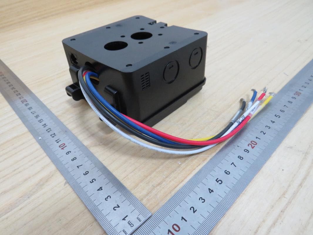
2APQIIT-AC-HUB-01
Jan 12, 2023Whole House Fan Hub
Equipment Class
DSC - Part 15 Security/Remote Control Transmitter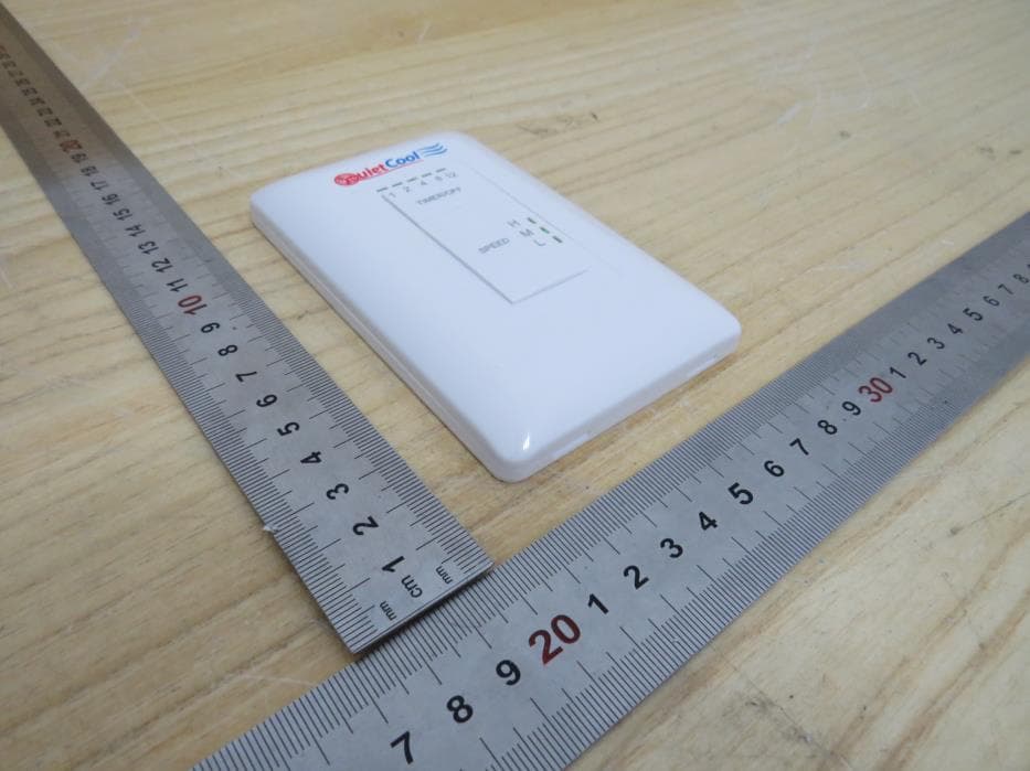
2APQIIT-RFSWITCH-02
Oct 01, 2022RF Switch
Equipment Class
DSC - Part 15 Security/Remote Control Transmitter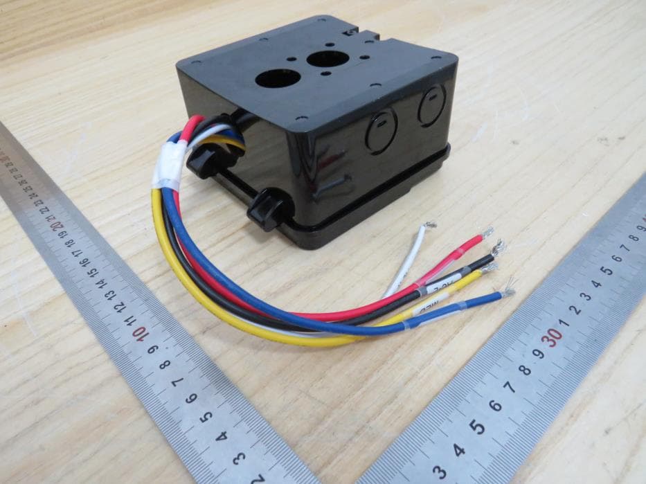
2APQIIT-RFHUB-02
Oct 01, 2022RF Hub
Equipment Class
DSR - Part 15 Remote Control/Security Device Transceiver
2APQIIT-AF-SMT
Jan 31, 2020Smart Attic Fan Control
Equipment Class
DSS - Part 15 Spread Spectrum Transmitter