2APZQ-ZYGO2TUnderwater Communication Radio
Swimmersive Co.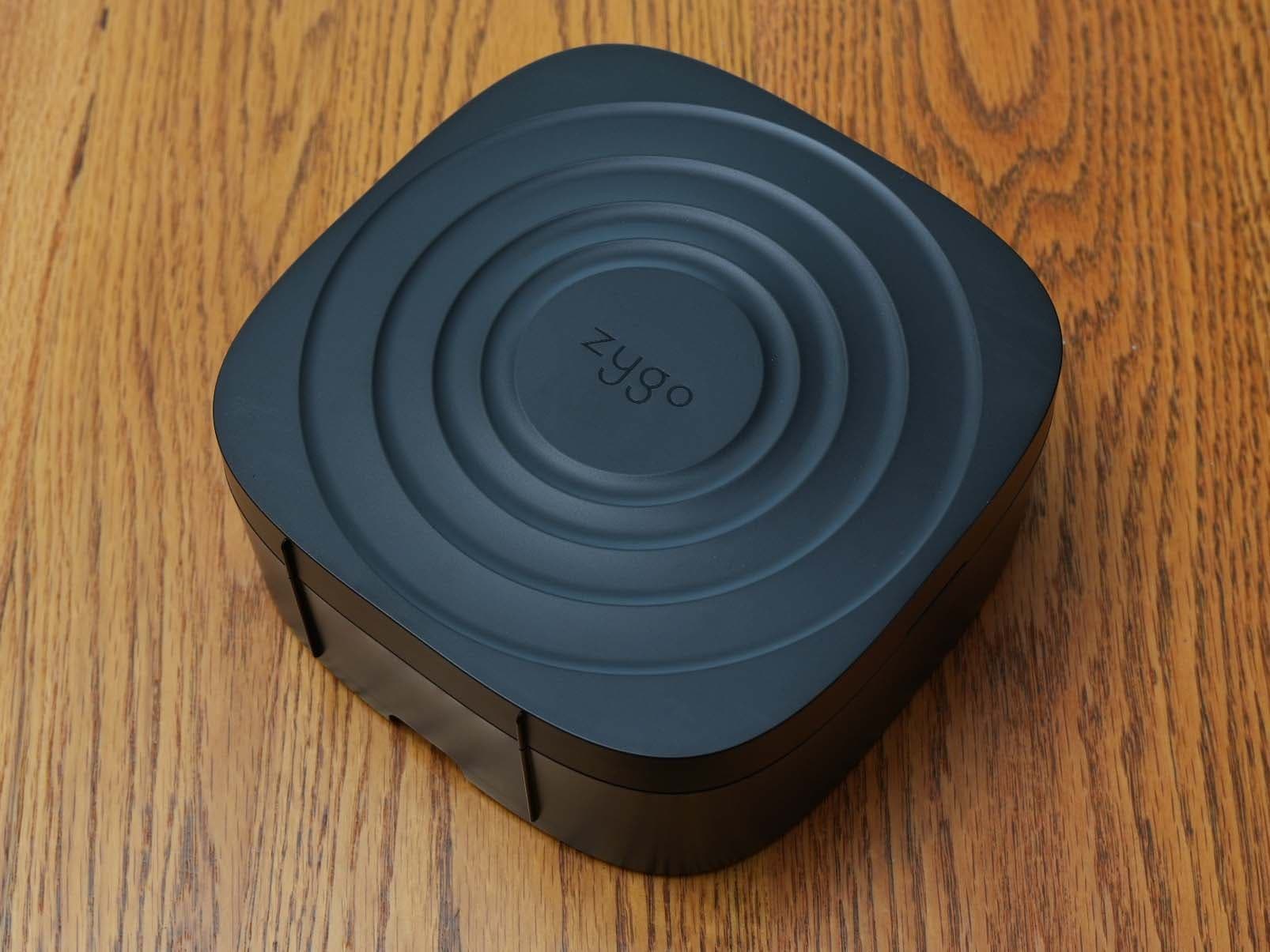
Click to zoom
Application Details
- Equipment Class
- DTS - Digital Transmission System
- Date of Grant
- Sep 10, 2024
- Application Purpose
- Original Equipment
- Date of Application
- Sep 10, 2024
- Equipment Note
- Underwater Communication Radio
- Frequency Range
- 2402.00000000 - 2480.00000000
- Company
- Swimmersive Co.
- Country
- United States
Documents & Files
Document Text
Text extracted from the exhibit documents filed with the FCC. Open a document above to read the original.
Users Manual
For assistance, email us on [email protected] This device operates on a no-interference, no-protection basis. Should the user seek to obtain protection from other radio services operating in the same TV bands, a radio license is required. For further details, consult Innovation, Science and Economic Development Canada's Client Procedures Circular CPC-2-1-28, Voluntary Licensing of Licence-Exempt Wireless Microphones in the TV Bands.
Attestation Statements
August 24, 2024 To: Federal Communications Commission Authorization and Evaluation Division 7435 Oakland Mills Road Columbia, MD 21046 USA Ref: Attestation Statements Part 2.911(d)(5)(i) and Part 2.911(d)(5)(ii) Filing Re. KDB 986446 D01 FCC ID: 2APZQ-ZYGO2T Dear Sir or Madam, Swimmersive Co. (“the applicant”) certifies that the equipment for which authorization is sought is not “covered” equipment prohibited from receiving an equipment authorization pursuant to section 2.903 of the FCC rules. We also certify that, as of the date of the filing of the application, the applicant is not identified on the Covered List as an entity producing “covered” equipment. If you have any questions, please contact us. Designated U.S. Agent Information: Name: Swimmersive Co Address: 2447 Pacific Coast Highway, 2nd Fl. Hermosa Beach, CA 90254 Contact Person: Sheera Goren Tel.: Email: [email protected] Sincerely, Sheera Goren
Attestation Statements
August 26, 2024 To: Federal Communications Commission Authorization and Evaluation Division 7435 Oakland Mills Road Columbia, MD 21046 USA Ref: Attestation Statements Part 2.911(d)(7) Filing FCC ID: 2APZQ-ZYGO2T FRN: 0027573781 Dear Sir or Madam, Swimmersive Co. (“the applicant”) certifies that, as of the date of the filing of the application, Sheera Goren is our designated U.S. agent for service of process for the above referenced FCC ID. Swimmersive Co. accepts to maintain an agent for no less than one year after the grantee has terminated all marketing and importation or the conclusion of any Commission-related proceeding involving the equipment. Swimmersive Co. accepts, as of the date of the filing of the application, the obligation of the designated U.S. agent for service of process for the above referenced FCC ID. Designated U.S. Agent Information: Name: Swimmersive Co Address: 2447 Pacific Coast Highway, 2nd Fl. Hermosa Beach, CA 90254 Contact Person: Sheera Goren Tel.: 818-445-2293 Email: [email protected] FRN: 0027573781 Sincerely, Sheera Goren
Cover Letter(s)
Request for Confidentiality Date: __06/13/24___ Subject: Confidentiality Request for: ____FCC ID: 2APZQ- ZYGO2T and IC ID: 23961- ZYGO2T___ Pursuant to FCC 47 CRF 0.457(d) and 0.459 and IC RSP-100, Section 9.4, the applicant requests that a part of the subject FCC application be held confidential. T ype of Confidentiality RequestedExhibit Short Term PermanentBlock Diagrams Short Term External Photos Short Term Permanent* 1 Internal Photos Short Term PermanentOperation Description/Theory of Operation Short Term PermanentParts List & Placement/BOM Short Term PermanentTune-Up Procedure Short Term PermanentSchematics Short Term Test Setup Photos Short Term Permanent* 1 User’s Manual Swimmersive Co. has spent substantial effort in developing this product and it is one of the first of its kind in industry. Having the subject information easily available to "competition" would negate the advantage they have achieved by developing this product. Not protecting the details of the design will result in financial hardship. Permanent Confidentiality: The applicant requests the exhibits listed above as permanently confidential be permanently withheld from public review due to materials that contain trade secrets and proprietary information not customarily released to the public. Short-Term Confidentiality: The applicant requests the exhibits selected above as short term confidential be withheld from public view for a period of 180 days from the date of the Grant of Equipment Authorization and prior to marketing. This is to avoid premature release of sensitive information prior to marketing or release of the product to the public. Applicant is also aware that they are responsible to notify our TCB in the event information regarding the product or the product is made available to the public. The Applicant understands that pursuant to Rule 0.457(d)(1)(ii), disclosure of this Application and all accompanying materials will not be made before the date of the Grant for this Application. Our TCB will then release the documents listed above for public disclosure pursuant to FCC Public Notice DA 04-1705. 1 - The asterisked items (*) require further information to be provided to our TCB before permanent confidentiality will be extended to these exhibits. Please refer to FCC KDB 726920 and the specific Document link for D01 found at: https://apps.fcc.gov/oetcf/kdb/forms/FTSSearchResultPage.cfm?switch=P&id=41731 and review section II, 3) regarding specific information that must accompany these requests. NOTE for Industry Canada Applications: IC currently only distinguishes Permanent Confidentiality exhibits as shown above. Short Term confidentiality is not considered applicable to IC applications. Sincerely, By: __________________________ __H. Stephen Berger_______ (Signature/Title) (Print name)
Cover Letter(s)
May 29, 2018 Swimmersive Co. 16854 Mooncrest Dr. Encino, CA 91436 To Whom It May Concern: Please be advised that Swimmersive Co. authorizes TEM Consulting and its president, H. Stephen Berger, to act on our behalf in regulatory matters, until otherwise notified. Thank you for your attention to this matter. Sincerely, Sheera Goren CEO Swimmersive Co. Sheera Goren CEO
External Photos
External Photos FCC ID: 2APZQ- ZYGO2T IC ID: 23961-ZYGO2T Description: Zygo Underwater Communication Radio Transmitter Model Name: Zygo2T Model Number: ZY600 Swimmersive Co. 2447 Pacific Coast Highway, 2nd Fl. Hermosa Beach, CA 90254 By TEM Consulting, LP 140 River Rd. Georgetown, TX 78628 June 2024 Figure 1 – The Zygo2 system Figure 2 –Zygo2T Transmitter – Oblique View Figure 3 – Zygo2T Transmitter – Bottom View Figure 4 – Zygo2T Transmitter – Antenna Raised Figure 5 – Zygo2T Transmitter – Cover Open
ID Label/Location Info
Label & Label Location FCC ID: 2APZQ- ZYGO2T IC: 23961-ZYGO2T Description: Zygo Underwater Communication Radio Transmitter Model Name: Zygo Model Number: ZY600 Swimmersive Co. 2447 Pacific Coast Highway, 2nd Fl. Hermosa Beach, CA 90254 By TEM Consulting, LP 140 River Rd. Georgetown, TX 78628 June 2024 Figure 1 – The Zygo2 system Note: 1.) Color of is PMS COOL GREY 1C Model: ZY600 ZYGO IC:23961-ZYGO2T FCC ID: 2APZQ-ZYGO2T Model: ZY600 ZYGO IC:23961-ZYGO2T FCC ID: 2APZQ-ZYGO2T 26mm 8mm
Internal Photos
Internal Photos FCC ID: 2APZQ- ZYGO2T IC: 23961-ZYGO2T Description: Zygo Underwater Communication Radio Transmitter Model Name: Zygo Model Number: ZY600 Swimmersive Co. 2447 Pacific Coast Highway, 2nd Fl. Hermosa Beach, CA 90254 By TEM Consulting, LP 140 River Rd. Georgetown, TX 78628 June 2024 Figure 1 – Interior of Zygo2 Transmitter Figure 2 – PWB Front of Zygo2 Transmitter Figure 3 - PWB back of Zygo2 Transmitter Figure 4 – Bluetooth RF Section of Zygo2 Transmitter Figure 5 – Bluetooth Low Frequency Radio RF Section of Zygo2 Transmitter
RF Exposure Info
RF Exposure Analysis Revision 4 FCC ID 2APZQ- ZYGO2T IC ID 23961- ZYGO2T Description: Zygo Underwater Communication Radio Transmitter Model Name: Zygo2 Model Number: ZY600 Swimmersive Co. 2447 Pacific Coast Highway, 2nd Fl. Hermosa Beach, CA 90254 By TEM Consulting, LP 140 River Rd. Georgetown, TX 78628 September 2024 TYPE CERTIFICATION Table of Contents Introduction ................................................................................................................................... 2 Product Description ...................................................................................................................... 2 Zygo Radios .................................................................................................................................. 2 FCC Requirements ........................................................................................................................ 2 ISED Canada Requirements ......................................................................................................... 3 Product Analysis ........................................................................................................................... 4 Bluetooth Radio ........................................................................................................................ 4 VHF Radio ................................................................................................................................ 4 Simultaneous Transmission ...................................................................................................... 4 Conclusion .................................................................................................................................... 4 Introduction This memo evaluates the Zygo2T, Zygo Underwater Communication Radio Transmitter, for RF exposure testing exclusion to the FCC USA and ISED Canada Requirements. Product Description The Swimmersive Zygo2 is a communication system for swimmers and swimming coaches. The Zygo2 system has 2 components. A transmitter to stream music to swimmers or for a coach to talk to his swimmers, called the Zygo Underwater Communication Radio Transmitter (Zygo transmitter or transmitter). A headset, worn by the swimmers, called the Zygo Underwater Communication Radio Headset. It’s primary use is to stream music to swimmers as they work out. It also allows a coach to give instructions to swimmers as they work out. The Zygo transmitter operates in the 174-216 MHz VHF band and 2.4 GHz ISM bands. The unit is battery powered. Zygo Radios The Zygo transmitter has two radios, a Bluetooth radio, operating in the 2.4 GHz ISM band, and the VHF transmitter to the headset, that operates in the 174-216 MHz band. For the Bluetooth radio the measured powers were: Frequency (MHz) Power (dBm) 2402 6.41 2441 6.21 2480 6.46 The Bluetooth channel with the highest measured power is the high channel at 2480 MHz with a measured power of 4.43 mW (6.46 dBm). The low frequency transmitter measured powers were: Frequency (MHz) Power (dBm) 175.0 18.861 194.5 11.328 209.5 10.785 The low frequency radio channel with the highest measured power is its low channel at 175.0 MHz with a measured power of 76.93 mW (18.861 dBm). The low frequency radio has a duty cycle of transmission for 3.4 mS followed by a 1.0 mS off time. This calculates to a duty cycle of 5.3 dB. FCC Requirements FCC KDB 447498 D01 V06 section 4.3 gives SAR test exclusion guidance: 4.3. General SAR test exclusion guidance 4.3.1. Standalone SAR test exclusion considerations .... a) For 100 MHz to 6 GHz and test separation distances ≤ 50 mm, the 1-g and 10-g SAR test exclusion thresholds are determined by the following: [(max. power of channel, including tune-up tolerance, mW) / (min. test separation distance, mm)] · [√f (GHz) ] ≤ 3.0 for 1-g SAR, and ≤ 7.5 for 10-g extremity SAR, 30 where • f (GHz) is the RF channel transmit frequency in GHz • Power and distance are rounded to the nearest mW and mm before calculation 31 • The result is rounded to one decimal place for comparison • The values 3.0 and 7.5 are referred to as numeric thresholds in step b) below The test exclusions are applicable only when the minimum test separation distance is ≤ 50 mm, and for transmission frequencies between 100 MHz and 6 GHz. When the minimum test separation distance is < 5 mm, a distance of 5 mm according to 4.1 f) is applied to determine SAR test exclusion. b) For 100 MHz to 6 GHz and test separation distances > 50 mm, the 1-g and 10-g SAR test exclusion thresholds are determined by the following (also illustrated in Appendix B): 1) {[Power allowed at numeric threshold for 50 mm in step a)] + [(test separation distance – 50 mm)·(f(MHz)/150)]} mW, for 100 MHz to 1500 MHz 2) {[Power allowed at numeric threshold for 50 mm in step a)] + [(test separation distance – 50 mm)·10]} mW, for > 1500 MHz and ≤ 6 GHz The formula can be used to calculate the maximum allowable power. The power of interest is the source-based time-averaged maximum conducted output power of the RF channel. The formula for the maximum allowable power, based on the guidance of section 4.3 in the KDB, is: 푃=푇∙퐷/√푓 • P is the source based time-averaged maximum conducted output power in mW • T is the numeric thresholds of 3.0 and 7.5 • D is the minimum separation distance in m • f is the RF channel transmit frequency in GHz For the highest frequency used, 216 MHz: For the highest frequency used, 2.48 GHz: • for a numeric threshold of 3.0 the maximum power is 9.6 mW • for a numeric threshold of 7.5 the maximum power is 23.8 mW ISED Canada Requirements Canadian regulation for RF exposure are contained in Spectrum Management and Telecommunications Radio Standards Specification RSS-102 Issue 5, March 2015, Radio Frequency (RF) Exposure Compliance of Radiocommunication Apparatus (All Frequency • for a numeric threshold of 3.0 the maximum power is 32.3 mW • for a numeric threshold of 7.5 the m…
Text truncated - open the document above for the full version.
Test Report
Antenna Revision 2 FCC ID: 2APZQ- ZYGO2T IC: 23961-ZYGO2T Description: Zygo Underwater Communication Radio Transmitter Model Name: Zygo Model Number: ZY600 Swimmersive Co. 2447 Pacific Coast Highway, 2 nd Fl. Hermosa Beach, CA 90254 By TEM Consulting, LP 140 River Rd. Georgetown, TX 78628 September 2024 The Zygo Transmitter has two antennas. One is for its VHF radio. The second is for its BLE radio. The VHF antenna is a “Meandered Dipole.” See Figure 1 and Figure 2. The Bluetooth LE (BLE) is a “PIFA” trace on the main PCBA. See Figure 3. The peak gain by tested channel for the Zygo Transmitter VHF antenna is in Table 1. The peak gain for the Zygo Transmitter BLE antenna is + 3.07 dBi. See Table 2. Figure 1 – Interior of Zygo2 Transmitter with its portion of the VHF antenna Figure 2- Zygo2 Transmitter extension with its portion of the VHF antenna Figure 3 – Bluetooth RF Section of Zygo2 Transmitter with “PIFA” antenna Table 1 – VHF antenna gain by frequency tested Gain Per Channel Tested Channel Frequency (MHz Gain Low 175.0 -4.99 Middle 194.5 3.50 High 209.5 3.48 Table 2- BLE antenna gain by frequency
Test Report
Project #: PRJ0050267 Company: Swimmersive Co. dba Zygo EUT Name: Zygo Underwater Comminication Radio Transmitter EUT Model: Zygo2T FCC and Industry Canada Wireless Test Report Prepared for: Swimmersive Co. dba Zygo 16854 Mooncrest Drive Encino, CA, 91436 By Nemko USA, Inc. 1601 North A.W. Grimes Blvd., Suite B Round Rock, Texas 78665 August 30, 2024 Written by Veer Patel Wireless Engineer PRJ0050267, Zygo2T Nemko USA, Inc. Page 2 of 50 Revision History Revision Number Description Date Draft01 Initial release for review 7/10/2024 Final01 Release to agency 8/2/2024 Final02 Added radiated band edge data for upper channel 8/30/2024 PRJ0050267, Zygo2T Nemko USA, Inc. Page 3 of 50 Table of C ontents Test Result Summary .................................................................................................................................................... 5 1.0 Introduction ..................................................................................................................................................... 6 1.1 Scope .......................................................................................................................................................... 6 1.2 EUT Description ........................................................................................................................................ 6 1.3 Support Equipment ..................................................................................................................................... 6 1.4 EUT Test Configuration ............................................................................................................................. 6 1.5 Modifications to Equipment ....................................................................................................................... 6 1.6 Test Setup ................................................................................................................................................... 6 1.7 Test Site ...................................................................................................................................................... 7 1.8 Measurement Corrections........................................................................................................................... 7 1.9 Applicable Documents ............................................................................................................................... 8 2.0 AC Power-line Conducted Emissions ............................................................................................................. 9 2.1 Test Procedure ............................................................................................................................................ 9 2.2 Test Criteria ................................................................................................................................................ 9 2.3 Test Results ................................................................................................................................................ 9 3.0 Occupied Bandwidth ..................................................................................................................................... 11 3.1 Test Procedure .......................................................................................................................................... 11 3.2 Test Criteria .............................................................................................................................................. 11 3.3 Test Results .............................................................................................................................................. 12 4.0 Fundamental Power....................................................................................................................................... 13 4.1 Test Procedure .......................................................................................................................................... 13 4.2 Test Criteria .............................................................................................................................................. 13 4.3 Test Results .............................................................................................................................................. 14 5.0 Power Spectral Density ................................................................................................................................. 15 5.1 Test Procedure .......................................................................................................................................... 15 5.2 Test Criteria .............................................................................................................................................. 15 5.3 Test Results .............................................................................................................................................. 16 6.0 Duty Cycle .................................................................................................................................................... 17 7.0 Band Edge ..................................................................................................................................................... 18 7.1 Test Procedure .......................................................................................................................................... 18 7.2 Test Criteria .............................................................................................................................................. 18 7.3 Test Results .............................................................................................................................................. 18 8.0 Conducted Antenna Port Spurious Emissions, Transmit Mode ........................................................…
Text truncated - open the document above for the full version.
Test Setup Photos
PRJ0050267 Setup Photos Page 1 of 4 Radiated Emissions, 30 MHz to 1 GHz PRJ0050267 Setup Photos Page 2 of 4 Radiated Emissions, 1 GHz to 26.5 GHz PRJ0050267 Setup Photos Page 3 of 4 Conducted Emissions PRJ0050267 Setup Photos Page 4 of 4 Power, Bandwidth, PSD, Conducted Spurious, Band Edge ***
Contact Information
Applicant
Sheera Goren(CEO)
Test Firm
Nemko USA, Inc.Larry Finn
[email protected]512-244-3371
Technical Specifications
| # | Rule Parts | Frequency Range | Power Output |
|---|---|---|---|
| 1 | 15C | 2.40 GHz - 2.48 GHz | 4.40 mW |
Other Applications from Swimmersive Co.
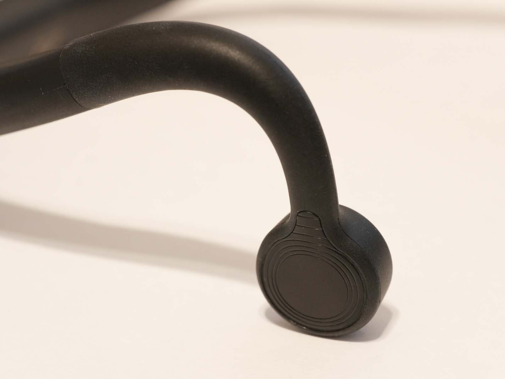
2APZQ-ZYGO2H
Sep 10, 2024Underwater Communication Radio Headset
Equipment Class
DWM - Part 15 Wireless Microphone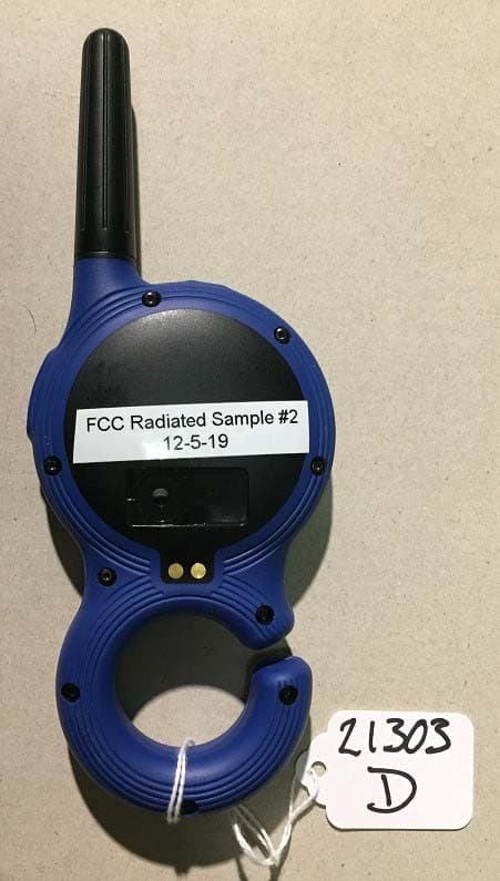
2APZQ-ZYGOV2
Oct 02, 2022Headset system for coaching swimmers
Equipment Class
DSS - Part 15 Spread Spectrum Transmitter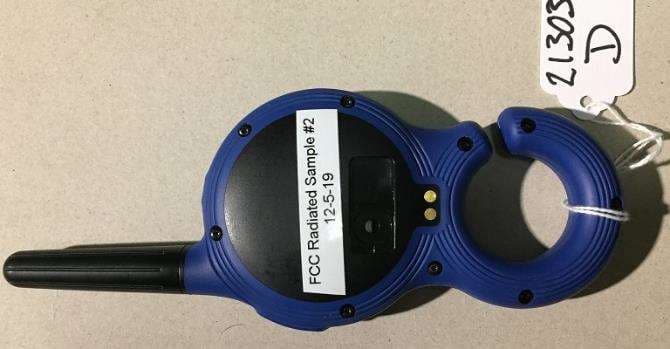
2APZQ-ZYGO
Jun 04, 2020Underwater communication radio
Equipment Class
DSS - Part 15 Spread Spectrum Transmitter