2APZQ-ZYGOV2Headset system for coaching swimmers
Swimmersive Co.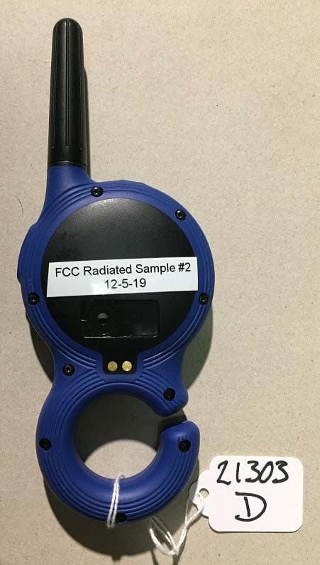
Click to zoom
Application Details
- Equipment Class
- DSS - Part 15 Spread Spectrum Transmitter
- Date of Grant
- Oct 02, 2022
- Application Purpose
- Original Equipment
- Date of Application
- Sep 29, 2022
- Equipment Note
- Headset system for coaching swimmers
- Frequency Range
- 2402.00000000 - 2480.00000000
- Company
- Swimmersive Co.
- Country
- United States
Documents & Files
Document Text
Text extracted from the exhibit documents filed with the FCC. Open a document above to read the original.
Cover Letter(s)
To Whom it May Concern Use of Prior Test Data This document explains the reuse of data from the first version of the Zygo product, FCC ID 2APZQ-ZYGO, for the second version of the Zygo product, FCC ID 2APZQ-ZYGOV2. The Bluetooth transmitter chip used in the first version of the Zygo product became unavailable, requiring that it be replaced by a different Bluetooth transmitter chip. This chip was replaced resulting in version two of the product. Other than necessary changes in the layout to receive the new Bluetooth chip, no other changes were made. Specifically, the VHF radio and its antenna were unchanged. The Bluetooth antenna is also identical between the two versions of the product. The units tested for both versions were fully populated an operational. Spot-checks of the VHF radio were performed during the emissions testing for spurious emissions and radiated harmonics. These spot-checks found that the characteristics of the VHF radio were unchanged. Given these factors, the radio parameter testing, and RF exposure analysis of the first version is being reused in the second version submission. Dated this 20 th day of August 2022 By: H. Stephen Berger Signature Printed Title: Regulatory Engineer On behalf of: Swimmersive Co. Telephone: (512) 864-3365
Cover Letter(s)
Request for Confidentiality Date: __08/12/22___ Subject: Confidentiality Request for: ____FCC ID: 2APZQ- ZYGOV2 and IC ID: 23961- ZYGOV2___ Pursuant to FCC 47 CRF 0.457(d) and 0.459 and IC RSP-100, Section 9.4, the applicant requests that a part of the subject FCC application be held confidential. T ype of Confidentiality RequestedExhibit Short Term PermanentBlock Diagrams Short Term External Photos Short Term Permanent* 1 Internal Photos Short Term PermanentOperation Description/Theory of Operation Short Term PermanentParts List & Placement/BOM Short Term PermanentTune-Up Procedure Short Term PermanentSchematics Short Term Test Setup Photos Short Term Permanent* 1 User’s Manual Swimmersive Co. has spent substantial effort in developing this product and it is one of the first of its kind in industry. Having the subject information easily available to "competition" would negate the advantage they have achieved by developing this product. Not protecting the details of the design will result in financial hardship. Permanent Confidentiality: The applicant requests the exhibits listed above as permanently confidential be permanently withheld from public review due to materials that contain trade secrets and proprietary information not customarily released to the public. Short-Term Confidentiality: The applicant requests the exhibits selected above as short term confidential be withheld from public view for a period of 180 days from the date of the Grant of Equipment Authorization and prior to marketing. This is to avoid premature release of sensitive information prior to marketing or release of the product to the public. Applicant is also aware that they are responsible to notify our TCB in the event information regarding the product or the product is made available to the public. The Applicant understands that pursuant to Rule 0.457(d)(1)(ii), disclosure of this Application and all accompanying materials will not be made before the date of the Grant for this Application. Our TCB will then release the documents listed above for public disclosure pursuant to FCC Public Notice DA 04-1705. 1 - The asterisked items (*) require further information to be provided to our TCB before permanent confidentiality will be extended to these exhibits. Please refer to FCC KDB 726920 and the specific Document link for D01 found at: https://apps.fcc.gov/oetcf/kdb/forms/FTSSearchResultPage.cfm?switch=P&id=41731 and review section II, 3) regarding specific information that must accompany these requests. NOTE for Industry Canada Applications: IC currently only distinguishes Permanent Confidentiality exhibits as shown above. Short Term confidentiality is not considered applicable to IC applications. Sincerely, By: __________________________ __H. Stephen Berger_______ (Signature/Title) (Print name)
Cover Letter(s)
May 29, 2018 Swimmersive Co. 16854 Mooncrest Dr. Encino, CA 91436 To Whom It May Concern: Please be advised that Swimmersive Co. authorizes TEM Consulting and its president, H. Stephen Berger, to act on our behalf in regulatory matters, until otherwise notified. Thank you for your attention to this matter. Sincerely, Sheera Goren CEO Swimmersive Co. Sheera Goren CEO
External Photos
External Photos FCC ID: 2APZQ- ZYGOV2 Description: Zygo Underwater Communication Radio Model Name: Zygo Model Number: ZY300 Swimmersive Co. 16854 Mooncrest DR Encino, CA 91436 By TEM Consulting, LP 140 River Rd. Georgetown, TX 78628 August 2022 Figure 1 – charge side view Figure 2 - side view
ID Label/Location Info
Label & Label Location FCC ID: 2APZQ- ZYGOV2 Description: Zygo Underwater Communication Radio Model Name: Zygo Model Number: ZY300 Swimmersive Co. 16854 Mooncrest DR Encino, CA 91436 By TEM Consulting, LP 140 River Rd. Georgetown, TX 78628 July 2022 Figure 1 – Zygo Coach’s Unit showing label and label location
Internal Photos
Internal Photos FCC ID: 2APZQ- ZYGOV2 IC: 23961-ZYGOV2 Description: Zygo Underwater Communication Radio Model Name: Zygo Model Number: ZY300 Swimmersive Co. 16854 Mooncrest DR Encino, CA 91436 By TEM Consulting, LP 140 River Rd. Georgetown, TX 78628 August 2022 Figure 1 - internal photo of Zygo Figure 2 - PWB front side with shield removed Figure 3 - PWB back side with shield removed Figure 4 - RF Section with Shield in Place Figure 5 - Bluetooth Section – Version 1 on Left, Version 2 on Right
RF Exposure Info
RF Exposure Analysis Revision 2 FCC ID 2APZQ- ZYGO Description: Zygo Underwater Communication Radio Model Name: Zygo Model Number: ZY100 Swimmersive Co. 16854 Mooncrest DR Encino, CA 91436 By TEM Consulting, LP 140 River Rd. Georgetown, TX 78628 June 2020 TYPE CERTIFICATION Table of Contents Introduction ................................................................................................................................... 2 Product Description ...................................................................................................................... 2 Zygo Radios .................................................................................................................................. 2 FCC Requirements ........................................................................................................................ 2 ISED Canada Requirements ......................................................................................................... 3 Product Analysis ........................................................................................................................... 4 Bluetooth Radio ........................................................................................................................ 4 Low Frequency Radio ............................................................................................................... 5 Simultaneous Transmission ...................................................................................................... 5 Conclusion .................................................................................................................................... 5 Introduction This memo evaluates the Zygo system coach’s unit for RF exposure testing exclusion to the FCC USA and ISED Canada Requirements. Product Description The Swimmersive Zygo is a communication system for swimmers and swimming coaches. The Zygo system has 2 components. A transmitter to stream music to swimmers or for a coach to talk to his swimmers, called the Zygo Coach’s Unit. A headset, that only receives, worn by the swimmers, called the Zygo Headset. It’s primary use is to stream music to swimmers as they work out. It also allows a coach to give instructions to swimmers as they work out. When coach’s use the unit to give instructions the unit operates push-to-talk (PTT) and the Bluetooth link is not active. In this mode the unit is handheld. The Zygo transmitter operates in the 174-216 MHz and 2.4 GHz ISM bands. The unit is battery powered. Zygo Radios The Zygo system coach’s unit has two radios, a Bluetooth radio, operating in the 2.4 GHz ISM band, and the low frequency transmitter to the headset, that operates in the 174-216 MHz band. The Bluetooth channel with the highest measured power is the low channel at 2402 MHz with a measured power of 11.0 mW (10.4 dBm). The low frequency radio channel with the highest measured power is its low channel at 176 MHz with a measured power of 67.3 mW (18.3 dBm). When used by a swimming coach the low frequency radio is a push-to-talk device. The low frequency radio has a duty cycle of transmission for 3.4 mS followed by a 1.0 mS off time. This calculates to a duty cycle of 5.3 dB. FCC Requirements FCC KDB 447498 D01 V06 section 4.3 gives SAR test exclusion guidance: 4.3. General SAR test exclusion guidance 4.3.1. Standalone SAR test exclusion considerations .... a) For 100 MHz to 6 GHz and test separation distances ≤ 50 mm, the 1-g and 10-g SAR test exclusion thresholds are determined by the following: [(max. power of channel, including tune-up tolerance, mW) / (min. test separation distance, mm)] ꞏ [√f (GHz)] ≤ 3.0 for 1-g SAR, and ≤ 7.5 for 10-g extremity SAR,30 where f(GHz) is the RF channel transmit frequency in GHz Power and distance are rounded to the nearest mW and mm before calculation31 The result is rounded to one decimal place for comparison The values 3.0 and 7.5 are referred to as numeric thresholds in step b) below The test exclusions are applicable only when the minimum test separation distance is ≤ 50 mm, and for transmission frequencies between 100 MHz and 6 GHz. When the minimum test separation distance is < 5 mm, a distance of 5 mm according to 4.1 f) is applied to determine SAR test exclusion. b) For 100 MHz to 6 GHz and test separation distances > 50 mm, the 1-g and 10-g SAR test exclusion thresholds are determined by the following (also illustrated in Appendix B): 1) {[Power allowed at numeric threshold for 50 mm in step a)] + [(test separation distance – 50 mm)ꞏ(f(MHz)/150)]} mW, for 100 MHz to 1500 MHz 2) {[Power allowed at numeric threshold for 50 mm in step a)] + [(test separation distance – 50 mm)ꞏ10]} mW, for > 1500 MHz and ≤ 6 GHz The formula can be used to calculate the maximum allowable power. The power of interest is the source-based time-averaged maximum conducted output power of the RF channel. The formula for the maximum allowable power, based on the guidance of section 4.3 in the KDB, is: 푃ൌ푇∙퐷/√푓 P is the source based time-averaged maximum conducted output power in mW T is the numeric thresholds of 3.0 and 7.5 D is the minimum separation distance in m f is the RF channel transmit frequency in GHz For the highest frequency used, 2.48 GHz: for a numeric threshold of 3.0 the maximum power is 9.6 mW for a numeric threshold of 7.5 the maximum power is 23.8 mW ISED Canada Requirements Canadian regulation for RF exposure are contained in Spectrum Management and Telecommunications Radio Standards Specification RSS-102 Issue 5, March 2015, Radio Frequency (RF) Exposure Compliance of Radiocommunication Apparatus (All Frequency Bands). Section 2.5.1, Exemption Limits for Routine Evaluation – SAR Evaluation, provides the following exclusion limits: The values listed are for a 1 gram tissue value. If a device is worn on a limb and subject to the 10 gram value the values in the table are multiplied by 2.5: For limb-worn devices where the…
Text truncated - open the document above for the full version.
RF Exposure Info
Project #: 23228-15 Company: Swimmersive Co. dba Zygo EUT Name: Swimmersive Zygo EUT Model: ZY300 RF Exposure Evaluation Report Prepared for: Swimmersive Co. dba Zygo 16854 Mooncrest Dr Encino, CA 91436 By Nemko PTI, Inc. 1601 North A.W. Grimes Blvd., Suite B Round Rock, Texas 78665 July 23, 2022 Written by Shakil Murad Wireless Engineer 23228-15, ZY300 Nemko PTI Page 2 of 6 Table of Contents 1.0 Maximum Permissible Exposure Evaluation (Supplements the test report.) ....................................................... 3 1.1 Applicable Documents .................................................................................................................................... 3 1.2 Criteria ............................................................................................................................................................ 3 1.1 Exposure Weighing Factor .............................................................................................................................. 4 1.2 Power to Exposure Calculation, Conducted .................................................................................................... 4 1.1 Antenna Separation Distance Analysis ........................................................................................................... 5 1.2 MPE Calculation – FCC ................................................................................................................................. 5 1.3 MPE Calculation – IC ..................................................................................................................................... 6 1.1 Conclusion ...................................................................................................................................................... 6 NOTICE: (1) This Report must not be used to claim product endorsement, by NVLAP, NIST, the FCC or any other Agency. This report also does not warrant certification by NVLAP or NIST. (2) This report shall not be reproduced except in full, without the written approval of Nemko PTI, Inc. (3) The significance of this report is dependent on the representative character of the test sample submitted for evaluation and the results apply only in reference to the sample tested. The manufacturer must continuously implement the changes shown herein to attain and maintain the required degree of compliance. 23228-15, ZY300 Nemko PTI Page 3 of 6 1.0 Maximum Permissible Exposure Evaluation (Supplements the test report.) The measured power is considered for the intended use of the device and resulting RF exposure to the user. 1.1 Applicable Documents Table 1.1.1: Applicable Documents Document Title RSS-102 Issue 5 Radio Frequency (RF) Exposure Compliance of Radiocommunication Apparatus (All Frequency Bands) KDB 447498 D01 General RF Exposure Guidance v06 RF EXPOSURE PROCEDURES AND EQUIPMENT AUTHORIZATION POLICIES FOR MOBILE AND PORTABLE DEVICES OET Bulletin 65 Edition 97-01 Evaluating Compliance with FCC Guidelines for Human Exposure to Radiofrequency Electromagnetic Fields 1.2 Criteria Section Reference Test Detail FCC 47 CFR Part 1 I, 1.1310 // RSS-102, Issue 5 Radiofrequency radiation exposure limits 23228-15, ZY300 Nemko PTI Page 4 of 6 1.1 Exposure Weighing Factor Duty cycle measurement is based on intervals not to exceed 100 msec. Maximum transmitter on time is divided by the lesser of 100 msec or the actual measured minimum transmitter interval time. The result is converted to dB and applied as needed to peak measurements of transmitter artifacts to determine average power. This is not a pass/fail measurement. Continuous packet transmission mode was used for the duty cycle measurement, which would represent a worst- case operating scenario. On Time (msec) Time Interval (msec) Duty Cycle (On Time/Interval) Exposure Weighing Factor (dB) (10 * Log 10 (Duty Cycle) 0.3772 1.25 = 0.31 = -5.2 Plotted measurements appear below: 1.2 Power to Exposure Calculation, Conducted The EUT transmitter power is determined by conducted measurement. Safe exposure distance was calculated for the allowed maximum uncontrolled public exposure limit. Measured Conducted Peak Power (dBm) Exposure Weighing Factor (dB) Antenna Gain (dBi) Corrected Peak Power EIRP (dBm) EIRP In Linear Terms (mW) 7.815 -5.20 -0.52 2.09 1.62 Transmit Event Time Time Interval (Return to channel time) 23228-15, ZY300 Nemko PTI Page 5 of 6 1.1 Antenna Separation Distance Analysis According to figure below antenna is located 8 mm from the outside edge of the unit’s chassis. Therefore, 8 mm is the closest contact distance from the antenna to the user. Antenna to Chassis Separation Distance 1.2 MPE Calculation – FCC According to KDB 447498 D01 General RF Exposure Guidance v06 section 4.3.1: a) For 100 MHz to 6 GHz and test separation distances ≤ 50 mm, the 1-g and 10-g SAR test exclusion thresholds are determined by the following: [(max. power of channel, including tune-up tolerance, mW)/(min. test separation distance, mm)] ·[√f(GHz)] ≤ 3.0 for 1-g SAR and ≤ 7.5 for 10-g extremity SAR, where - f(GHz) is the RF channel transmit frequency in GHz - Power and distance are rounded to the nearest mW and mm before calculation - The result is rounded to one decimal place for comparison Calculated power (max power including tune up tolerance) = 1.62 mW. SAR exemption calculation applying 8 mm separation distance: [(1.62 mW)/(8 mm)] · [√2.48 (GHz)] = 0.32 So, 0.32 ≤ 3.0 at a separation distance of 8 mm. 23228-15, ZY300 Nemko PTI Page 6 of 6 1.3 MPE Calculation – IC SAR evaluation – Exemption limits for routine evaluation based on frequency and separation distance. Applying above Table 1, row 2450 MHz, the linear interpolation of 8 mm seperation distance limit is: X = 8 mm (EUT antenna to housing separation distance) X1 = 5 mm, Y1 = 4 mW X2 = 10 mm, Y2 = 7 mW Limit = (Y2-Y1)/(X2-X1) * (X-X1) + Y1 = (7-4)/(10-5) * (8-5) + 4 =5.8 mV So, 1.62 mV < 5.8 mV at a separation distance of 8 mm. 1.1 Conc…
Text truncated - open the document above for the full version.
Test Report
Address all correspondences regarding this report to: Timothy Milam Custom Integrated Antennas 1322 Butcher Hollow, PO Box 116 Van Lear, KY 41265 Tel: (512) 638-2643 E-mail: [email protected] Document #: CIA 2020-0017.002 Custom Integrated Antennas Timothy Milam 1322 Butcher Hollow, PO Box 116, Van Lear, KY 41265 Page #: 1 of 7 Tel: (512) 638-2643 Custom Integrated Antennas (CIA) “Zygo Coach’s Unit Bluetooth Antenna Report” 02/17/2020) (Reference “Zygo Coach’s Unit VHF Antenna Report_CIA 09- 20-2022” for That Antenna Data Analysis.) Originally Submitted to Zygo on: February 17, 2020 Zygo Coach’s Unit Bluetooth Antenna Analysis Document #: CIA 2020-0017.002 Custom Integrated Antennas Timothy Milam 1322 Butcher Hollow, PO Box 116, Van Lear, KY 41265 Page #: 2 of 7 Tel: (512) 638-2643 Table of Contents 1 DUT Description ................................................................................................................4 1.1 Zygo Coach’s Unit ..................................................................................................... 4 1.1.1 External View ..........................................................................................................4 1.1.2 Internal View ...........................................................................................................4 1.2 PIFA Antenna Component ........................................................................................ 4 2 Test Equipment Used ........................................................................................................5 3 Key Antenna Specifications ..............................................................................................5 4 Measured Data ..................................................................................................................6 4.1 VSWR......................................................................................................................... 6 4.2 Principal Radiated Patterns ...................................................................................... 6 4.2.1 Vertically Polarized DUT (V-Pol) ............................................................................6 4.2.2 Horizontally Polarized DUT (H-Pol) ........................................................................7 4.3 Tabular Data Summary............................................................................................. 7 5 Conclusion .........................................................................................................................7 Zygo Coach’s Unit Bluetooth Antenna Analysis Document #: CIA 2020-0017.002 Custom Integrated Antennas Timothy Milam 1322 Butcher Hollow, PO Box 116, Van Lear, KY 41265 Page #: 3 of 7 Tel: (512) 638-2643 Revision History Date of Revision Revision Comments Pages Affected 11/07/2019 Entire Document All 09/20/2022 Updated title with current information, added the “Key Antenna Specifications” table on page 7, added note on page 8 regarding the DUT name, added the “Peak Gain” details paragraph at the end of the “Conclusions” section on page 9. Also, the “Table of Contents” changed as a result of the additions. 1, 2, 7, 8, and 9 Zygo Coach’s Unit Bluetooth Antenna Analysis Document #: CIA 2020-0017.002 Custom Integrated Antennas Timothy Milam 1322 Butcher Hollow, PO Box 116, Van Lear, KY 41265 Page #: 4 of 7 Tel: (512) 638-2643 Zygo Coach’s Unit Bluetooth Antenna Report (CIA_02/17/2020) 1 DUT Description 1.1 Zygo Coach’s Unit 1.1.1 External View 1.1.2 Internal View 1.2 PIFA Antenna Component Bluetooth PIFA Bluetooth PIFA Zygo Coach’s Unit Bluetooth Antenna Analysis Document #: CIA 2020-0017.002 Custom Integrated Antennas Timothy Milam 1322 Butcher Hollow, PO Box 116, Van Lear, KY 41265 Page #: 5 of 7 Tel: (512) 638-2643 2 Test Equipment Used • Test Range = 13 ft. x 9 ft. x 9 ft. Rectangular Anechoic Chamber with Cummings Microwave C- RAM SFC-18 in. pyrimidal absorber total coverage, except for 72 inches of SFC-18 Walkway an d full corner treatment with 3 in. C-RAM Cornerblock. The DUT / Test antenna seperation was 46 inches. • Test (Site Source) Antenna = RFSpin Model QRH11, 700 MHz – 11 GHz Quadridge Horn, S/N: 200721Q11 • Vector Network Analyzer “VNA” = Pico Technology Model “PicoVNA 106 300 kHz – 6 GHz Quad RX, S/N: A0063/08671. • TX Coaxial Cable = 20 ft. Times Microwave LMR-240 Low Loss cable with Pasternack PE44637 Crimp/Solder SMA-Male connectors on both ends. • RX Coaxial Cable = 37 ft. Times Microwave LMR-400 Low Loss cable with Pasternack PE44668 Crimp/Solder Type N-Male connectors on both ends. • TX Adapter = Pasternack PE91339, N-Male to SMA-Female Adapter to VNA • RX Adapter = Pasternack PE9082 N-Female to SMA-Male Adapter to DUT • Channel Master 360 degree programmable turntable with Styrofoam pedestal DUT mounting platform 3 Key Antenna Specifications Antenna Parameter Values / Comments Antenna Type Custom PCB Trace PIFA Frequency Band (MHz) 2400 - 2500 Nominal Impedance 50 Ω Peak Gain (dBi) Highest gain measured of all data points -0.52 (Found at 2448 MHz and angle 247.5 degrees in the V-Pol Azimuth plane plot below) Efficiency (%) Average efficiency of all data points measured 24.6 Pattern Characteristics Overall Pattern Shape Omni-Directional HPBW (Half Power Beam Width) Typical (N/A) Front-to-back Ratio (Typical) (N/A) 2:1 VSWR Band Width (MHz) 100+ Connection Requirement None (PCB Trace) Power Handling (Watts) 5 Physical Dimensions Length (mm) 26 Width or diameter (mm) 6 Depth or thickness (mm) 1 oz. Material Copper PCB trace Zygo Coach’s Unit Bluetooth Antenna Analysis Document #: CIA 2020-0017.002 Custom Integrated Antennas Timothy Milam 1322 Butcher Hollow, PO Box 116, Van Lear, KY 41265 Page #: 6 of 7 Tel: (512) 638-2643 4 Measured Data NOTE: The DUT referred to in the measured data below as “Handset” is referred to as “Coach’s Unit” elsewhere in this report and other filing documents. 4.1 VSWR 4.2 Principal Radiated Patterns 4.2.1 Vertically Polarized…
Text truncated - open the document above for the full version.
Test Report
Address all correspondences regarding this report to: Timothy Milam Custom Integrated Antennas 1322 Butcher Hollow, PO Box 116 Van Lear, KY 41265 Tel: (512) 638-2643 E-mail: [email protected] Document #: CIA 2019-0017.009 Custom Integrated Antennas Timothy Milam 1322 Butcher Hollow, PO Box 116, Van Lear, KY 41265 Page #: 1 of 9 Tel: (512) 638-2643 Custom Integrated Antennas (CIA) “Zygo Coach’s Unit VHF Antenna Report” 11/07/2019) (Reference “Zygo Coach’s Unit Bluetooth Antenna Report_CIA 09-20-2022” for That Antenna Data Analysis.) Originally Submitted to Zygo on: November 07, 2019 Zygo Coach’s Unit VHF Antenna Analysis Document #: CIA 2019-0017.009 Custom Integrated Antennas Timothy Milam 1322 Butcher Hollow, PO Box 116, Van Lear, KY 41265 Page #: 2 of 9 Tel: (512) 638-2643 Table of Contents 1 DUT Description ................................................................................................................4 1.1 Zygo Coach’s Unit ..................................................................................................... 4 1.1.1 External View ..........................................................................................................4 1.1.2 Internal View ...........................................................................................................4 1.2 Antenna Components ................................................................................................ 5 1.2.1 Radiating Element (Radiator) ...................................................................................5 1.2.2 Counterpoise ............................................................................................................6 2 Test Equipment Used ........................................................................................................6 3 Key Antenna Specifications ..............................................................................................7 4 Measured Data ..................................................................................................................8 4.1 VSWR......................................................................................................................... 8 4.2 Principal Radiated Patterns ...................................................................................... 8 4.2.1 Vertically Polarized DUT (V-Pol) ............................................................................8 4.2.2 Horizontally Polarized DUT (H-Pol) ........................................................................9 4.3 Tabular Data Summary............................................................................................. 9 5 Conclusion .........................................................................................................................9 Zygo Coach’s Unit VHF Antenna Analysis Document #: CIA 2019-0017.009 Custom Integrated Antennas Timothy Milam 1322 Butcher Hollow, PO Box 116, Van Lear, KY 41265 Page #: 3 of 9 Tel: (512) 638-2643 Revision History Date of Revision Revision Comments Pages Affected 11/07/2019 Entire Document All 09/20/2022 Updated title with current information, added the “Key Antenna Specifications” table on page 7, added note on page 8 regarding the DUT name, added the “Peak Gain” details paragraph at the end of the “Conclusions” section on page 9. Also, the “Table of Contents” changed as a result of the additions. 1, 2, 7, 8, and 9 Zygo Coach’s Unit VHF Antenna Analysis Document #: CIA 2019-0017.009 Custom Integrated Antennas Timothy Milam 1322 Butcher Hollow, PO Box 116, Van Lear, KY 41265 Page #: 4 of 9 Tel: (512) 638-2643 Zygo Coach’s Unit VHF Antenna Report (CIA_11/07/2019) 1 DUT Description 1.1 Zygo Coach’s Unit 1.1.1 External View 1.1.2 Internal View VHF Radiator VHF Counterpoise Zygo Coach’s Unit VHF Antenna Analysis Document #: CIA 2019-0017.009 Custom Integrated Antennas Timothy Milam 1322 Butcher Hollow, PO Box 116, Van Lear, KY 41265 Page #: 5 of 9 Tel: (512) 638-2643 1.2 Antenna Components 1.2.1 Radiating Element (Radiator) Zygo Coach’s Unit VHF Antenna Analysis Document #: CIA 2019-0017.009 Custom Integrated Antennas Timothy Milam 1322 Butcher Hollow, PO Box 116, Van Lear, KY 41265 Page #: 6 of 9 Tel: (512) 638-2643 1.2.2 Counterpoise 2 Test Equipment Used • Test Range = Open Air Test Site “OATS”. DUT and test antenna seperation was 120 inches. • Test (Site Source) Antenna = ETS EMCO Model 3146 Log Periodic Antenna S/N: 9401-3791 • Vector Network Analyzer “VNA” = Pico Technology Model “PicoVNA 106 300 kHz – 6 GHz Quad RX, S/N: A0063/08671. • Coaxial Cables = 2 (one TX and one RX) Mini Circuits CBL-25FT-SMSM+ • Adapters = 2 (one TX and one RX) Pasternack PE91339, Precision N-Male to SMA-Female Adapters • Channel Master 360 degree programmable turntable with Styrofoam pedestal DUT mounting platform Zygo Coach’s Unit VHF Antenna Analysis Document #: CIA 2019-0017.009 Custom Integrated Antennas Timothy Milam 1322 Butcher Hollow, PO Box 116, Van Lear, KY 41265 Page #: 7 of 9 Tel: (512) 638-2643 3 Key Antenna Specifications Antenna Parameter Values / Comments Antenna Type Custom Helical Dipole with an internal conformal counterpoise having three helical sections and a single 2 stage (varied diameters) radiating element mostly residing outside the housing in a screw on radome and soldered directly to the PCBA transmission line through hole and pad feed point internally. Frequency Band (MHz) 174-216 Nominal Impedance 50 Ω Peak Gain (dBi) Highest gain measured of all data points -5.50 (Found at 216 MHz and angle 135 degrees in the H-Pol Azimuth plane plot below) Efficiency (%) Average efficiency of all data points measured 4.84 Pattern Characteristics Overall Pattern Shape Omni-Directional HPBW (Half Power Beam Width) Typical (N/A) Front-to-back Ratio (Typical) (N/A) 2:1 VSWR Band Width (MHz) 7 Connection Requirement Soldered to a PCB Through Hole / Pad Power Handling (Watts) 5 Physical Dimensions See production drawings above Length (mm) …
Text truncated - open the document above for the full version.
Test Report
Project 21303-15 Swimmersive Co. dba Zygo Zygo Coach Wireless Certification Report Wireless Microphone (VHF) Section Prepared for: Swimmersive 16854 Mooncrest Dr Encino, CA 91436 By Professional Testing (EMI), Inc. 1601 North A.W. Grimes Blvd., Suite B Round Rock, Texas 78665 29 Apr 2020 Reviewed by Written by Shakil Murad Lead EMC Engineer Eric Lifsey EMC Engineer Swimmersive –ZY100 – VHF Section 21303 Professional Testing (EMI) In…
Text truncated - open the document above for the full version.
Contact Information
Applicant
Sheera Goren(CEO)
Test Firm
Professional Testing (EMI), Inc.Larry Finn
Technical Specifications
| # | Rule Parts | Frequency Range | Power Output |
|---|---|---|---|
| 1 | 15C | 2.40 GHz - 2.48 GHz | 6.00 mW |
Other Applications from Swimmersive Co.
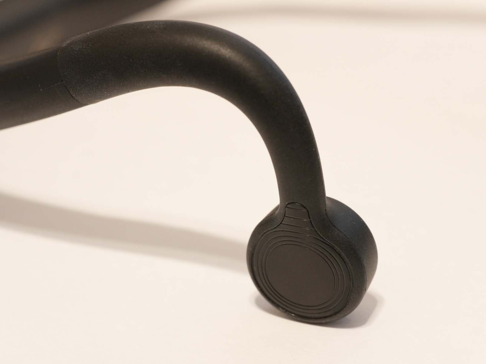
2APZQ-ZYGO2H
Sep 10, 2024Underwater Communication Radio Headset
Equipment Class
DWM - Part 15 Wireless Microphone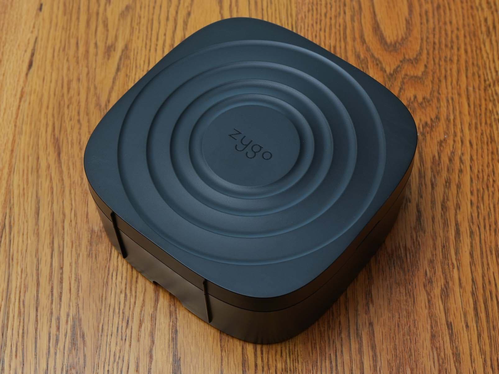
2APZQ-ZYGO2T
Sep 10, 2024Underwater Communication Radio
Equipment Class
DTS - Digital Transmission System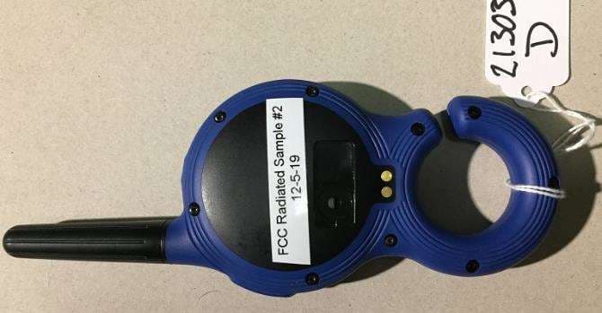
2APZQ-ZYGO
Jun 04, 2020Underwater communication radio
Equipment Class
DSS - Part 15 Spread Spectrum Transmitter