2ARDBC-8031UWiFi & BLE module
Beijing Kingsmith Technology Co.,Ltd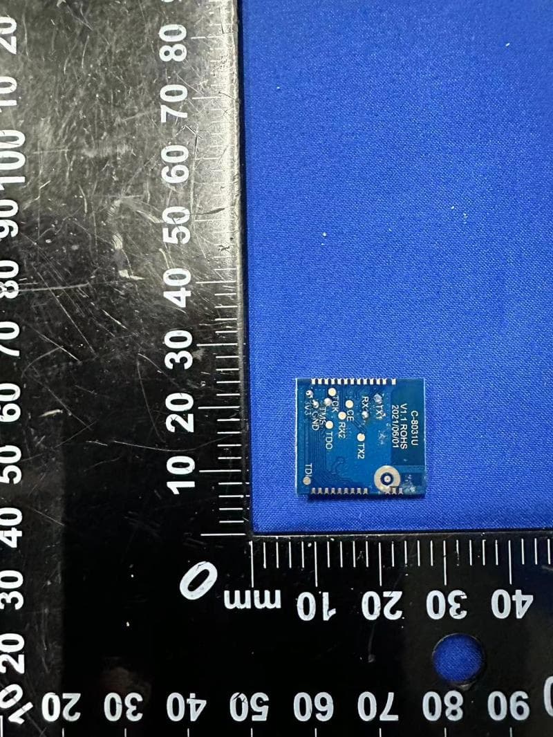
Click to zoom
Application Details
- Equipment Class
- DTS - Digital Transmission System
- Date of Grant
- Mar 01, 2023
- Application Purpose
- Original Equipment
- Date of Application
- Mar 01, 2023
- Equipment Note
- WiFi & BLE module
- Frequency Range
- 2412.00000000 - 2462.00000000
- Country
- China
Documents & Files
Document Text
Text extracted from the exhibit documents filed with the FCC. Open a document above to read the original.
Users Manual
C-8031U The C-8031U is an integrated WIFI& Bluetooth BLE dual-mode module, using BK7231M_QFN32 Bluetooth dual-mode 5.1 and Wi-Fi 802.11n The chip.Integrated with the hardware and software resources needed for complete Wi-Fi and Bluetooth applications, it can support dual role connectivity of AP and STA, and Both classic Bluetooth and Bluetooth low power connections are supported.Up to 120 MHz of 32-bit MCU and 256 KB of built-in RAM, Can make the chip support multi-cloud connection. The C-8031U has a wealth of peripherals, such as PWM, I2C, UART, SPI, SDIO, and IrDA.You can directly use UART Load and burn program.Up to six channels of 32-bit high speed PWM output using the chip are ideal for high quality LED control.Every 2 PWM can Configured for phase controlled differential mode to support motor and strip drives. The C-8031U integrates a prioritized Wi-Fi and Bluetooth control module to implement real-time priority and send/receive scheduling.C-8031U External PA and LNA extensions can be supported by providing an indication of the status of the current transceiver. The C-8031U is embedded with eFUSE and supports OTP read and write in FLASH. It can be used to provide unique serial numbers, encrypt codes, and protect calls The interface is secure.Internal integration of true random number generator and security module to ensure safe communication and fast authentication and network connection. C-8031U supports a low-power sleep mode, where the MCU can enter a sleep state and achieve a microamperage sleep current.Supported by the C-8031U In deep sleep mode, you can run a 32-bit clock at a few microamps and wake up by this clock or by any GPIO. The C-8031U module has an onboard antenna and an external antenna is optional Working voltage: DC 3.3-3.6V, Operating temperature: -20°C to +85°C 802.11 b/g/n 1 x1 standard 17 dBm 54 Mbps output power 54 Mbps sensitivity - 76 dBm And STBC 20 MHz bandwidth support STA, AP, and Direct mode support AP and STA parallel dual roles MCU speed to 120 MHz Internal RAM 256 KB 2 MB or 4 MB internal Flash Download UART and SPI SDIO 50 MHz clock frequency high-speed SPI interface double the I2C interface six-way 32-bit counter and a low power consumption six-way support high-speed clock or low power clock PWM output all ten multi-channel high-speed ADC, and support internal filtering to 16 EFUSE 32 bytes 256 Byte ~ 2 KByte OTP true random number generator 26 MHz and 32 KHz clock signal output 1.1 List of applicable FCC rules: The module complies with FCC Part 15.247. 1.2 Summarize the specific operational use conditions: The module has been certified for Fix, Mobile, Portable applications. This transmitter must not be co‐located or operating in conjunction with any other antenna or transmitter. 1.3 Limited module procedures: The module has its own RF shielding, which belong to signal module Standard requires: Clear and specific instructions describing the conditions, limitations and procedures for third‐ parties to use and/or integrate the module into a host device (see Comprehensive integration instructions below). Resolve: Supply example as follows: Installation Notes: 1) C-8031U Module Power supply range is DC 3.3V~3.6V, when you use C-8031U Module design product, the power supply cannot exceed this range. 2) When connect C-8031U Module to the host device, the host device must be power off. 3) Make sure the module pins correctly installed. 4) Make sure that the module does not allow users to replace or demolition. 1.4 Trace antenna designs: Not applicable. 1.5 RF exposure considerations: This equipment complies with FCC RF radiation exposure limits set forth for an uncontrolled environment. The antenna(s) used for this transmitter must not be collocated or operating in conjunction with any other antenna or transmitter. Note: the host product manuals must include a statement in order to alert the users of FCC RF exposure compliance. 1.6 Antennas PCB antenna, 1dBi The antenna is permanently attached, can’t be replaced. 1.7 Label and compliance information This device complies with part 15 of the FCC rules. Operation is subject to the following two conditions: (1) this device may not cause harmful interference, and (2) this device must accept any interference received, including interference that may cause undesired operation. Warning: Changes or modifications to this unit not expressly approved by the party responsible for compliance could void the user’s authority to operate the equipment. NOTE: This equipment has been tested and found to comply with the limits for a Class B digital device, pursuant to part 15 of the FCC Rules. These limits are designed to provide reasonable protection against harmful interference in a residential installation. This equipment generates uses and can radiate radio frequency energy and, if not installed and used in accordance with the instructions, may cause harmful interference to radio communications. However, there is no guarantee that interference will not occur in a particular installation. If this equipment does cause harmful interference to radio or television reception, which can be determined by turning the equipment off and on, the user is encouraged to try to correct the interference by one or more of the following measures: ‐ Reorient or relocate the receiving antenna. ‐ Increase the separation between the equipment and receiver. ‐Connect the equipment into an outlet on a circuit different from that to which the receiver is connected. ‐Consult the dealer or an experienced radio/TV technician for help. The system integrator must place an exterior label on the outside of the final product housing the B100 Modules. Below is the content that must be included on this label. The host product Labeling Requirements: NOTICE: The host product must make sure that FCC labeling requirements are met. This includes clearly visible exterior label on the outside of the final product housing that d…
Text truncated - open the document above for the full version.
Attestation Statements
2023-02-21 Eurofins Electrical and Electronic Testing NA, Inc. 914 West Patapsco Avenue Baltimore, MD 21230 RE: Attestation Statements Part 2.911(d)(5)(i) request for FCC ID: 2ARDBC-8031U [Beijing Kingsmith Technology Co.,Ltd] certifies that the equipment for which authorization is sought is not “covered” equipment prohibited from receiving an equipment authorization pursuant to section 2.903 of the FCC rules. Sincerely, Name: ChengxiangGu 2023-02-21 Eurofins Electrical and Electronic Testing NA, Inc. 914 West Patapsco Avenue Baltimore, MD 21230 RE: Attestation Statements Part 2.911(d)(5)(ii) request for FCC ID: 2ARDBC-8031U Beijing Kingsmith Technology Co.,Ltd certifies that, as of the date of the filing of the application, the applicant is not identified on the Covered List as an entity producing “covered” equipment. Sincerely, Name: ChengxiangGu
Attestation Statements
U.S. Agent Designation for Service of Process (Applicant and U.S. Agent are Separate Parties) TO: Federal Communications Commission 7435 Oakland Mills Road Columbia, MD 21046 ATTENTION: FCC Certification – Section 2.911(d)(7) Information Designated U.S. Agent Company Name: Baihetian Innovative Solutions FRN: 0033401605 Contact Name: Kenneth Young Street Address: 6837 Chase Rd City/Province/Zip: Dearborn, MI 48126 Telephone No: 313-395-3113 Email: [email protected] This letter is to confirm that we (“the Designated U.S. Agent) have accepted the responsibility to act as the Designated U.S. Agent for Service of Process as required by section 47 CFR 2.911(d)(7) on behalf of the Applicant noted below. U.S. Agent Signature: Date: Feb 21, 2023 Signed by (Printed Name/Title): Kenneth Young/Manager The Applicant acknowledges that they must maintain an agent for no less than one year after terminating all marketing and importation OR the conclusion of any Commission-related proceeding involving the equipment. The applicant further acknowledges their responsibility to inform the FCC whenever the Designated U.S. Agent information above changes. Applicant Company name: Beijing Kingsmith Technology Co.,Ltd Grantee Code: 2ARDB FCC ID: 2ARDBC-8031U Contact Name: Chengxiang Gu Street Address: Floor 4, Building 25, Area 18, ABP Park, Fengtai, Beijing, China. City/Province/Zip: Beijing Telephone No: 010 83680970 Email: [email protected] Applicant Signature: Date: February 21, 2023 Signed by (Printed Name/Title): Chengxiang Gu /Quality manager
Cover Letter(s)
Request for Modular/Limited Modular Approval Date: February 25, 2023 Subject: Manufacturer’s Declaration for ☒ - Modular Approval ☐ - Split Modular Approval ☐ - Limited Modular Approval ☐ - Limited Split Modular Approval Confidentiality Request for: ______ 2ARDBC-8031U ______ 8 Basic Requirements – FCC Part 15.212(a)(1) For Items Marked “NO(*)”, the Limited Module Description Must be Filled Out on the Following Pages Modular Approval Requirement Requirement Met 1. The modular transmitter must have its own RF shielding. This is intended to ensure that the module does not have to rely upon the shielding provided by the device into which it is installed in order for all modular transmitter emissions to comply with FCC limits. It is also intended to prevent coupling between the RF circuitry of the module and any wires or circuits in the device into which the module is installed. Such coupling may result in non-compliant operation. The physical crystal and tuning capacitors may be located external to the shielded radio elements. 15.212(a)(1)(i) ☒ - YES ☐ - NO(*) Details: The module have RF shielding. 2. The modular transmitter must have buffered modulation/data inputs (if such inputs are provided) to ensure that the module will comply with FCC requirements under conditions of excessive data rates or over-modulation. 15.212(a)(1)(ii) ☒ - YES ☐ - NO(*) Details: Data to the modulation circuit is buffered as described in the operational description provided with the application 3. The modular transmitter must have its own power supply regulation on the module. This is intended to ensure that the module will comply with FCC requirements regardless of the design of the power supplying circuitry in the device into which the module is installed. 15.212(a)(1)(iii) ☒ - YES ☐ - NO(*) Details: The module contains its own power supply regulation. Please refer to schematic filed with this application 4. The modular transmitter must comply with the antenna and transmission system requirements of §§ 15.203, 15.204(b), 15.204(c), 15.212(a), and 2.929(b). The antenna must either be permanently attached or employ a ‘‘unique’’ antenna coupler (at all connections between the module and the antenna, including the cable). The ‘‘professional installation’’ provision of § 15.203 is not applicable to modules but can apply to limited modular approvals under paragraph 15.212(b). 15.212(a)(1)(iv) ☒ - YES ☐ - NO(*) Details: The module have an PCB antenna 5. The modular transmitter must be tested in a stand-alone configuration, i.e., the module must not be inside another device during testing. This is intended to demonstrate that the module is capable of complying with Part 15 emission limits regardless of the device into which it is eventually installed. Unless the transmitter module will be battery powered, it must comply with the AC line conducted requirements found in Section 15.207. AC or DC power lines and data input/output lines connected to the module must not contain ferrites, unless they will be marketed with the module (see Section 15.27(a)). The length of these lines shall be length typical of actual use or, if that length is unknown, at least 10 centimeters to insure that there is no coupling between the case of the module and supporting equipment. Any accessories, peripherals, or support equipment connected to the module during testing shall be unmodified or commercially available (see Section 15.31(i)). 15.212(a)(1)(v) ☒ - YES ☐ - NO(*) Details: The module was tested stand-alone as shown in test setup photographs filed with this application Modular Approval Requirement Requirement Met 6. The modular transmitter must be labeled with its own FCC ID number, or use an electron display (see KDB Publication 784748). If using a permanently affixed label with its own FCC ID number, if the FCC ID is not visible when the module is installed inside another device, then the outside of the device into which the module is installed must also display a label referring to the enclosed module. This exterior label can use wording such as the following: “Contains Transmitter Module FCC ID: XYZMODEL1” or “Contains FCC ID: XYZMODEL1.” Any similar wording that expresses the same meaning may be used. The Grantee may either provide such a label, an example of which must be included in the application for equipment authorization, or, must provide adequate instructions along with the module which explain this requirement. In the latter case, a copy of these instructions must be included in the application for equipment authorization. If the modular transmitter uses an electronic display of the FCC identification number, the information must be readily accessible and visible on the modular transmitter or on the device in which it is installed. If the module is installed inside another device, then the outside of the device into which the module is installed must display a label referring to the enclosed module. This exterior label can use wording such as the following: “Contains FCC certified transmitter module(s).” Any similar wording that expresses the same meaning may be used. The user manual must include instructions on how to access the electronic display. A copy of these instructions must be included in the application for equipment authorization. 15.212(a)(1)(vi) ☒ - YES ☐ - NO(*) Details: There is a label on the module as shown in the labeling exhibit filed with this application. Host specific labeling instructions are shown in the installation manual .filed with this application. 7. The modular transmitter must comply with all specific rule or operating requirements applicable to the transmitter, including all the conditions provided in the integration instructions by the grantee. A copy of these instructions must be included in the application for equipment authorization. For example, there are very strict operational and timing requirements that must be met before a transmitter is authorized for operation under Section 15.2…
Text truncated - open the document above for the full version.
Cover Letter(s)
Date: February 21, 2023 Eurofins Electrical and Electronic Testing NA, Inc. 914 West Patapsco Avenue Baltimore, MD 21230 RE: CONFIDENTIALITY REQUEST FOR (WiFi & BLE module / C-8031U / FCC ID: 2ARDBC-8031U ) To Whom It May Concern: This letter serves as an official request for confidentiality under sections 0.457 and 0.459 of CFR 47. We have requested that the (Block Diagrams, Schematics, Operational Descriptions) required to be submitted with this application be permanently withheld from public review. The above documents are company proprietary information that could never get into the possession of your competition. Please contact me if there is any information you may need. Sincerely, Signature: Name: Chengxiang Gu Applicant: Beijing Kingsmith Technology Co.,Ltd Address: Floor 4, Building 25, Area 18, ABP Park, Fengtai, Beijing, China. TEL: 010 83680970
Cover Letter(s)
date: February 21, 2023 Eurofins Electrical and Electronic Testing NA, Inc. 914 West Patapsco Avenue Baltimore, MD 21230 RE: LETTER OF AGENT AUTHORIZATION To Whom It May Concern: We, the undersigned, hereby authorize (Eurofins Electrical Testing Service (Shenzhen) Co., Ltd.) to act on our behalf in all matters relating to application for equipment authorization, including the signing of all documents relating to these matters. We also hereby certify that no party to the application authorized hereunder is subject to the denial of benefits, including FCC benefits, pursuant to Section 5301 of the Anti-Drug Abuse Act of 1988, 21 U.S.C.853(a). This agreement expires one year from the current date. Sincerely, Signature: Name: Chengxiang Gu Applicant: Beijing Kingsmith Technology Co.,Ltd Address: Floor 4, Building 25, Area 18, ABP Park, Fengtai, Beijing, China. TEL: 010 83680970
ID Label/Location Info
FCC ID: 2ARDBC-8031U IC: 25276-C8031U C-8031U
RF Exposure Info
1 Safety Human Exposure 1.1 Radio Frequency Exposure Compliance 1.1.1 Electromagnetic Fields RESULT: Pass Test Specification Test standard : CFR47 FCC Part 2: Section 2.1091 CFR47 FCC Part 1: Section 1.1310 FCC KDB Publication 447498 v06, section 7 FCC ID: 2ARDBC-8031U IC: 25276-C8031U RSS-102 Issue 5 March 2015, section 2.5.2 FCC requirements FCC requirement: Systems operating under the provisions of this section shall be operated in a manner that ensures that the public is not exposed to radio frequency energy level in excess limit for maximum permissible exposure. In accordance with 47 CFR FCC Part 2 Subpart J, section 2.1091 this device has been defined as a mobile device whereby a distance of 20cm normally can be maintained between the user and the device. MPE Calculation Method according to KDB 447498 v06 Power Density: S (mW/cm 2 ) = PG/4πR 2 or EIRP/4πR 2 Where: S = power density (mW/cm 2 ) P = power input to the antenna (mW) G = power gain of the antenna in the direction of interest relative to an isotropic radiator R = distance to the center of radiation of the antenna (cm) From the maximum conducted output power, the minimum mobile separation distance, d=20 cm, as well as the antenna gain, the RF power density can be calculated as below: S(mW/cm2)= PG/4πR2 a) EUT RF Exposure Evaluation operations, Worst Case mode Test Mode Measured Power (dBm) Antenna Gain (dBi) Measured e.i.r.p (dBm) S(mW/cm 2 )= PG/4πR 2 Limit (mW/cm 2 ) BLE 2.8 1 3.8 0.0005 1.0 2.4GHz band Wi-Fi 12.5 1 13.5 0.0045 1.0 The EUT power density for transmit simultaneously is 0.005 mW/cm 2 it is less than the limit 1.0 mW/cm 2 IC requirements: The EUT shall comply with the requirement of RSS-102 section 4 Exposure Limits. a) EUT RF Exposure Evaluation standalone operations, Worst Case mode Test Mode Maximum e.i.r.p (dBm) Maximum e.i.r.p (W) Limit (W) 2.4GHz band Wi-Fi 13.5 0.02238 2.68 “RF Radiation Exposure Statement Caution: This Transmitter must be installed to provide a separation distance of at least 20 cm from all persons.”
Test Report
1 Antenna describe 1. Antenna describe; Antenna plate Monoploe antenna Make name/model name C-8031U Antenna gain 1.45dBi Frequency range 2.4GHZ—2.4835GHZ Connector type Direct Location of mearement (company name) XIAMENSHI C-CHIP TECHNOLOGY CO., LTD Manufacturer SHENZHENSHI XINZHONGXIN TECHNOLOGY CO., LTD. Manufacturer address A3 Building, Donghuan Industrial Zone, Shajing, Baoan District, Shenzhen 2. External view drawing; Picture of antenna (unit:mm) 2 System 3 S-parameter 4 2400M Theta=90 5 Phi=0 Phi=90 6 2450M Theta=90 7 Phi=0 Phi=90 8 2470M Theta=90 9 Phi=0 Phi=90 10
Test Report
Appendix A: DTS Bandwidth Test Result TestMode Antenna Frequency[MHz] DTS BW [MHz] FL[MHz] FH[MHz] Limit[MHz] Verdict BLE_1M Ant1 2402 0.688 2401.704 2402.392 0.5 PASS 2440 0.704 2439.696 2440.400 0.5 PASS 2480 0.740 2479.648 2480.388 0.5 PASS Test Graphs BLE_1M_Ant1_2402 BLE_1M_Ant1_2440 BLE_1M_Ant1_2480 Appendix B: Occupied Channel Bandwidth Test Result TestMode Antenna Frequency[MHz] OCB [MHz] FL[MHz] FH[MHz] Limit[MHz] Verdict BLE_1M Ant1 2402 1.0708 2401.4945 2402.5653 --- --- 2440 1.0906 2439.4819 2440.5725 --- --- 2480 1.1107 2479.4744 2480.5851 --- --- Test Graphs BLE_1M_Ant1_2402 BLE_1M_Ant1_2440 BLE_1M_Ant1_2480 Appendix C: Maximum conducted output power Test Result TestMode Antenna Frequency[MHz] Conducted Powert[dBm] Conducted Limit[dBm] EIRP[dBm] EIRP Limit[dBm] Verdict BLE_1M Ant1 2402 1.15 ≤30 2.15 ≤36 PASS 2440 1.88 ≤30 2.88 ≤36 PASS 2480 2.8 ≤30 3.8 ≤36 PASS Appendix D: Maximum power spectral density Test Result TestMode Antenna Frequency[MHz] Result[dBm/3kHz] Limit[dBm/3kHz] Verdict BLE_1M Ant1 2402 -14.71 ≤8.00 PASS 2440 -13.66 ≤8.00 PASS 2480 -12.7 ≤8.00 PASS Test Graphs BLE_1M_Ant1_2402 BLE_1M_Ant1_2440 BLE_1M_Ant1_2480 Appendix E: Band edge measurements Test Result TestMod e Antenn a ChNam e Frequency[MHz ] RefLevel[dBm ] Result[dBm ] Limit[dBm ] Verdic t BLE_1M Ant1 Low 2402 -0.02 -44.85 ≤-20.02 PASS High 2480 2.39 -43.46 ≤-17.61 PASS Test Graphs BLE_1M_Ant1_Low_2402 BLE_1M_Ant1_High_2480 Appendix F: Conducted Spurious Emission Test Result TestMod e Antenn a Frequency[MHz ] FreqRange [MHz] RefLeve l [dBm] Result[dBm ] Limit[dBm ] Verdic t BLE_1M Ant1 2402 Reference 0.62 0.62 --- PASS 30~1000 0.62 -57.55 ≤-19.38 PASS 1000~2650 0 0.62 -43.19 ≤-19.38 PASS 2440 Reference 1.55 1.55 --- PASS 30~1000 1.55 -57.83 ≤-18.45 PASS 1000~2650 0 1.55 -42.33 ≤-18.45 PASS 2480 Reference 2.39 2.39 --- PASS 30~1000 2.39 -57.57 ≤-17.61 PASS 1000~2650 0 2.39 -41.35 ≤-17.61 PASS Test Graphs BLE_1M_Ant1_2402_0~Reference BLE_1M_Ant1_2402_30~1000 BLE_1M_Ant1_2402_1000~26500 BLE_1M_Ant1_2440_0~Reference BLE_1M_Ant1_2440_30~1000 BLE_1M_Ant1_2440_1000~26500 BLE_1M_Ant1_2480_0~Reference BLE_1M_Ant1_2480_30~1000 BLE_1M_Ant1_2480_1000~26500 Appendix G: Duty Cycle Test Result TestMode Antenna Frequency[MHz] ON Time [ms] Period [ms] Duty Cycle [%] BLE_1M Ant1 2402 2.14 2.50 85.60 2440 2.13 2.50 85.20 2480 2.14 2.50 85.60 Test Graphs BLE_1M_Ant1_2402 BLE_1M_Ant1_2440 BLE_1M_Ant1_2480 Appendix H: Emissions in Restricted Bands Test Result Mode: 1M-2402 NO. Freq. [MHz] Level [dBμV/m] Factor [dB/m] Limit [dBμV/m] Margin [dB] Height [cm] Angle [°] Polarity 1 2310 46.57 6.48 74.00 27.43 150 330 Horizontal 2 2327.84 47.50 6.52 74.00 26.50 150 30 Horizontal 3 2331.36 47.71 6.52 74.00 26.29 150 20 Horizontal 4 2351.28 47.37 6.56 74.00 26.63 150 320 Horizontal 5 2365.12 47.33 6.60 74.00 26.67 150 270 Horizontal 6 2390 45.73 6.64 74.00 28.27 150 30 Horizontal Suspected Data List NO. Freq. [MHz] Level [dBμV/m] Factor [dB/m] Limit [dBμV/m] Margin [dB] Height [cm] Angle [°] Polarity 1 2310 46.39 6.48 74.00 27.61 150 170 Vertical 2 2311.6 47.62 6.48 74.00 26.38 150 20 Vertical 3 2337.44 47.56 6.54 74.00 26.44 150 310 Vertical 4 2356.88 47.42 6.58 74.00 26.58 150 170 Vertical 5 2364.64 47.79 6.58 74.00 26.21 150 280 Vertical 6 2390 46.25 6.64 74.00 27.75 150 230 Vertical Mode: 1M-2480 NO. Freq. [MHz] Level [dBμV/m] Factor [dB/m] Limit [dBμV/m] Margin [dB] Height [cm] Angle [°] Polarity 1 2483.5 46.91 7.20 74.00 27.09 150 250 Horizontal 2 2488.58 2 48.99 7.24 74.00 25.01 150 220 Horizontal 3 2493.82 9 47.53 7.27 74.00 26.47 150 300 Horizontal 4 2494.86 85 47.78 7.27 74.00 26.22 150 330 Horizontal 5 2495.85 85 47.74 7.29 74.00 26.26 150 210 Horizontal 6 2500 47.38 7.31 74.00 26.62 150 170 Horizontal NO. Freq. [MHz] Level [dBμV/m] Factor [dB/m] Limit [dBμV/m] Margin [dB] Height [cm] Angle [°] Polarity 1 2483.5 46.79 7.20 74.00 27.21 150 110 Vertical 2 2488.43 35 48.29 7.24 74.00 25.71 150 50 Vertical 3 2494.01 05 48.83 7.27 74.00 25.17 150 20 Vertical 4 2494.01 05 48.83 7.27 74.00 25.17 150 20 Vertical 5 2499.27 4 48.76 7.31 74.00 25.24 150 190 Vertical 6 2500 46.60 7.31 74.00 27.40 150 300 Vertical Note: 1. The Antenna Gain is compensated in the graph. 2. The limit in dBm for average detector is conversion from 54dBuV/m, according to 15.209(a). The limit in dBm for peak detector is 20dB above the limit of average detector in dBm. Appendix I: Spurious emissions Mode: 1M-2402 Test Graph NO. Freq. [MHz] Level [dBμV/m] Factor [dB/m] Limit [dBμV/m] Margin [dB] Height [cm] Angle [°] Polarity Verdict 1 34.85 25.31 -16.53 40.00 14.69 100 70 Vertical PASS 2 36.79 26.55 -16.19 40.00 13.45 100 170 Vertical PASS 3 95.96 26.12 -20.30 43.50 17.38 100 130 Vertical PASS 4 143.49 25.94 -16.69 43.50 17.56 100 290 Vertical PASS 5 167.74 35.88 -16.56 43.50 7.62 100 180 Vertical PASS 6 191.99 33.11 -19.09 43.50 10.39 100 320 Vertical PASS Mode: 1M-2402 Test Graph NO. Freq. [MHz] Level [dBμV/m] Factor [dB/m] Limit [dBμV/m] Margin [dB] Height [cm] Angle [°] Polarity Verdict 1 156.1 14.44 -16.12 43.50 29.06 100 60 Horizontal PASS 2 191.99 19.42 -19.09 43.50 24.08 100 30 Horizontal PASS 3 464.56 17.26 -12.35 46.00 28.74 100 150 Horizontal PASS 4 566.41 17.96 -10.32 46.00 28.04 100 100 Horizontal PASS 5 631.4 20.02 -8.75 46.00 25.98 100 100 Horizontal PASS 6 826.37 22.65 -6.37 46.00 23.35 100 260 Horizontal PASS Mode: 1M-2440 Test Graph NO. Freq. [MHz] Level [dBμV/m] Factor [dB/m] Limit [dBμV/m] Margin [dB] Height [cm] Angle [°] Polarity Verdict 1 34.85 23.79 -16.53 40.00 16.21 100 330 Vertical PASS 2 36.79 26.88 -16.19 40.00 13.12 100 130 Vertical PASS 3 95.96 27.11 -20.30 43.50 16.39 100 200 Vertical PASS 4 143.49 25.04 -16.69 43.50 18.46 100 250 Vertical PASS 5 167.74 35.98 -16.56 43.50 7.52 100 90 Vertical PASS 6 191.99 31.93 -19.09 43.50 11.57 100 240 Vertical PASS Mode: 1M-2440 Test Graph NO. Freq. [MHz] Level [dBμV/m] Factor [dB/m] Limit [dBμV/m] Margin [dB] Height [cm] Angle [°] Polarity Verdict 1 156.1 15.25 -16.12 43.50 28.25 100 14…
Text truncated - open the document above for the full version.
Test Report
Appendix A: DTS Bandwidth Test Result TestMode Antenna Frequency[MHz] DTS BW [MHz] FL[MHz] FH[MHz] Limit[MHz] Verdict 11B Ant1 2412 9.000 2407.480 2416.480 0.5 PASS 2437 8.560 2432.920 2441.480 0.5 PASS 2462 10.000 2456.960 2466.960 0.5 PASS 11G Ant1 2412 16.320 2403.800 2420.120 0.5 PASS 2437 16.280 2428.840 2445.120 0.5 PASS 2462 16.320 2453.800 2470.120 0.5 PASS 11N20SISO Ant1 2412 17.560 2403.200 2420.760 0.5 PASS 2437 17.040 2428.440 2445.480 0.5 PASS 2462 17.600 2453.160 2470.760 0.5 PASS Test Graphs 11B_Ant1_2412 11B_Ant1_2437 11B_Ant1_2462 11G_Ant1_2412 11G_Ant1_2437 11G_Ant1_2462 11N20SISO_Ant1_2412 11N20SISO_Ant1_2437 11N20SISO_Ant1_2462 Appendix B: Occupied Channel Bandwidth Test Result TestMode Antenna Channel Frequency[MHz] OCB [MHz] FL[MHz] FH[MHz] Limit[MHz] Verdict 11B Ant1 2412 14.204 2404.8831 2419.0871 --- --- 2437 14.178 2429.8915 2444.0695 --- --- 2462 14.207 2454.8760 2469.0830 --- --- 11G Ant1 2412 17.346 2403.2053 2420.5513 --- --- 2437 17.281 2428.3528 2445.6338 --- --- 2462 17.200 2453.3476 2470.5476 --- --- 11N20SISO Ant1 2412 18.318 2402.8352 2421.1532 --- --- 2437 18.197 2427.8784 2446.0754 --- --- 2462 18.220 2452.8697 2471.0897 --- --- Test Graphs 11B_Ant1_2412 11B_Ant1_2437 11B_Ant1_2462 11G_Ant1_2412 11G_Ant1_2437 11G_Ant1_2462 11N20SISO_Ant1_2412 11N20SISO_Ant1_2437 11N20SISO_Ant1_2462 Appendix C: Maximum conducted output power Test Result TestMode Antenna Frequen cy[MHz] Conducted Powert[dBm] Conducted Limit[dBm] EIRP [dBm] EIRP Limit[dBm] Verdict 11B Ant1 2412 12.31 ≤30.00 13.76 ≤36.00 PASS 2437 12.43 ≤30.00 13.88 ≤36.00 PASS 2462 12.50 ≤30.00 13.95 ≤36.00 PASS 11G Ant1 2412 11.04 ≤30.00 12.49 ≤36.00 PASS 2437 11.29 ≤30.00 12.74 ≤36.00 PASS 2462 11.34 ≤30.00 12.79 ≤36.00 PASS 11N20SIS O Ant1 2412 9.96 ≤30.00 11.41 ≤36.00 PASS 2437 9.95 ≤30.00 11.40 ≤36.00 PASS 2462 10.19 ≤30.00 11.64 ≤36.00 PASS Appendix D: Maximum power spectral density Test Result TestMode Antenna Frequency[MHz] Result[dBm/3-100kHz] Limit[dBm/3kHz] Verdict 11B Ant1 2412 -19.12 ≤8.00 PASS 2437 -18.58 ≤8.00 PASS 2462 -18.55 ≤8.00 PASS 11G Ant1 2412 -21.44 ≤8.00 PASS 2437 -21.08 ≤8.00 PASS 2462 -20.95 ≤8.00 PASS 11N20SISO Ant1 2412 -21.47 ≤8.00 PASS 2437 -21.47 ≤8.00 PASS 2462 -20.99 ≤8.00 PASS Test Graphs 11B_Ant1_2412 11B_Ant1_2437 11B_Ant1_2462 11G_Ant1_2412 11G_Ant1_2437 11G_Ant1_2462 11N20SISO_Ant1_2412 11N20SISO_Ant1_2437 11N20SISO_Ant1_2462 Appendix E: Band edge measurements Test Result TestMode Antenn a ChNam e Frequency[MH z] RefLevel[dB m] Result[dB m] Limit[dBm ] Verdic t 11B Ant1 Low 2412 3.47 -43.3 ≤-26.53 PASS High 2462 4.03 -46.47 ≤-25.97 PASS 11G Ant1 Low 2412 0.26 -32.49 ≤-29.74 PASS High 2462 0.03 -45.72 ≤-29.97 PASS 11N20SIS O Ant1 Low 2412 -1.07 -34.69 ≤-31.07 PASS High 2462 -0.57 -45.76 ≤-30.57 PASS Test Graphs 11B_Ant1_Low_2412 11B_Ant1_High_2462 11G_Ant1_Low_2412 11G_Ant1_High_2462 11N20SISO_Ant1_Low_2412 11N20SISO_Ant1_High_2462 Appendix F: Conducted Spurious Emission Test Result TestMode Antenna Frequency[MHz] FreqRange [Mhz] RefLevel [dBm] Result [dBm] Limit [dBm] Verdict 11B Ant1 2412 Reference 4.12 4.12 --- PASS 30~1000 4.12 -57.75 ≤-25.88 PASS 1000~26500 4.12 -49.16 ≤-25.88 PASS 2437 Reference 4.14 4.14 --- PASS 30~1000 4.14 -57.84 ≤-25.86 PASS 1000~26500 4.14 -49.91 ≤-25.86 PASS 2462 Reference 4.03 4.03 --- PASS 30~1000 4.03 -58.44 ≤-25.97 PASS 1000~26500 4.03 -49.79 ≤-25.97 PASS 11G Ant1 2412 Reference 0.30 0.30 --- PASS 30~1000 0.30 -57.47 ≤-29.7 PASS 1000~26500 0.30 -49.08 ≤-29.7 PASS 2437 Reference 0.03 0.03 --- PASS 30~1000 0.03 -57.74 ≤-29.97 PASS 1000~26500 0.03 -49.57 ≤-29.97 PASS 2462 Reference 0.22 0.22 --- PASS 30~1000 0.22 -57.91 ≤-29.78 PASS 1000~26500 0.22 -49.36 ≤-29.78 PASS 11N20SISO Ant1 2412 Reference -1.03 -1.03 --- PASS 30~1000 -1.03 -57.88 ≤-31.03 PASS 1000~26500 -1.03 -48.22 ≤-31.03 PASS 2437 Reference -0.69 -0.69 --- PASS 30~1000 -0.69 -57.3 ≤-30.69 PASS 1000~26500 -0.69 -49.34 ≤-30.69 PASS 2462 Reference -0.54 -0.54 --- PASS 30~1000 -0.54 -57.89 ≤-30.54 PASS 1000~26500 -0.54 -50.13 ≤-30.54 PASS Test Graphs 11B_Ant1_2412_0~Reference 11B_Ant1_2412_30~1000 11B_Ant1_2412_1000~26500 11B_Ant1_2437_0~Reference 11B_Ant1_2437_30~1000 11B_Ant1_2437_1000~26500 11B_Ant1_2462_0~Reference 11B_Ant1_2462_30~1000 11B_Ant1_2462_1000~26500 11G_Ant1_2412_0~Reference
Test Report
11G_Ant1_2412_30~1000 11G_Ant1_2412_1000~26500 11G_Ant1_2437_0~Reference 11G_Ant1_2437_30~1000 11G_Ant1_2437_1000~26500 11G_Ant1_2462_0~Reference 11G_Ant1_2462_30~1000 11G_Ant1_2462_1000~26500 11N20SISO_Ant1_2412_0~Reference 11N20SISO_Ant1_2412_30~1000 11N20SISO_Ant1_2412_1000~26500 11N20SISO_Ant1_2437_0~Reference 11N20SISO_Ant1_2437_30~1000 11N20SISO_Ant1_2437_1000~26500 11N20SISO_Ant1_2462_0~Reference 11N20SISO_Ant1_2462_30~1000 11N20SISO_Ant1_2462_1000~26500 Appendix F: Duty Cycle Test Result TestMode Antenna Frequency[MHz] Transmission Duration [ms] Transmission Period [ms] Duty Cycle [%] 11B Ant1 2412 12.43 12.55 99.04 2437 9.00 9.00 100.00 2462 7.00 7.00 100.00 11G Ant1 2412 2.06 2.19 94.06 2437 2.07 2.20 94.09 2462 2.07 2.19 94.52 11N20SISO Ant1 2412 1.92 2.04 94.12 2437 1.92 2.05 93.66 2462 1.92 2.05 93.66 Test Graphs 11B_Ant1_2412 11B_Ant1_2437 …
Text truncated - open the document above for the full version.
Contact Information
Applicant
Chengxiang Gu(Quality manager)
Technical Contact
Beijing Kingsmith Technology Co.,LtdChengxiang Gu
[email protected]010 83680970
Floor 4, Building 25, Area 18, ABP Park, Fengtai, · Beijing · China
Test Firm
Eurofins E&E Hursley LtdAndrew Coombes
Technical Specifications
| # | Rule Parts | Frequency Range | Power Output |
|---|---|---|---|
| 2 | 15C | 2.41 GHz - 2.46 GHz | 17.78 mW |
Other Applications from Beijing Kingsmith Technology Co.,Ltd

2ARDB-RMWM10F
Dec 01, 2024Trifold Water Rowing Machine
Equipment Class
DTS - Digital Transmission System
2ARDB-TRF0FB
Nov 20, 2021Motorized Treadmill
Equipment Class
DXX - Part 15 Low Power Communication Device Transmitter
2ARDB-WPS1F
Apr 13, 2020WalkingPad Walking Device
Equipment Class
DTS - Digital Transmission System
2ARDB-TRR11B
Mar 11, 2020Motorized Treadmill
Equipment Class
DTS - Digital Transmission System