2ARRB-VM34BUVideo Baby Monitor
Meizhou Guo Wei Electronics Co., Ltd
Click to zoom
Application Details
- Equipment Class
- DSS - Part 15 Spread Spectrum Transmitter
- Date of Grant
- Jun 29, 2021
- Application Purpose
- Original Equipment
- Date of Application
- Jun 29, 2021
- Equipment Note
- Video Baby Monitor
- Frequency Range
- 2402.00000000 - 2477.00000000
- Country
- China
Documents & Files
Document Text
Text extracted from the exhibit documents filed with the FCC. Open a document above to read the original.
Users Manual
Motorola VM34 4.3" Video Baby Monitor User Guide For: VM34, VM34-2, VM34-3 and VM34-4 Welcome... to your new Motorola Video Baby Monitor! Thank you for purchasing the Video Baby Monitor. Now you can see and hear your baby sleeping in another room or you can monitor your older children in their playroom. Please keep your original dated sales receipt for your records. For warranty service of your Motorola product, you will need to provide a copy of your dated sales receipt to confirm warranty status. Registration is not required for warranty coverage. For questions, warranty, support or service related to the product, please contact us by visit: This User’s Guide has all the information you need to make the most out of your product. Please read the Safety Instructions on pages 8-9 before you install the unit. Inside the Box • 1 x Parent Unit • 1 x Baby Unit (Camera) •2 x Power adapter (Parent Unit and Baby Unit) •1 x Quick Start Quide In multi-camera packs, you will find one or more additional Camera Units with power adapters. motorolanursery.com/support Overview of the Parent Unit 1.Display (LCD screen) 2.Parent Unit ON/OFF and Charging LED Red when the parent unit is ON. Purple when electrical outlet connected. Blue when off and connected to electrical outlet. 3.Audio Level LEDs (Green, Green, Amber, Red, Red) 4.MENU button Press to open / close the Menu options. 5.VIDEO ON/OFF button Press to turn the LCD screen ON/OFF (Note: audio is maintained.) 6.Navigation button Move Up/Down/Right/Left menu options. 7.OK button 8.Power button Press and Hold to turn the Parent Unit ON/OFF . 9.TALK button Press and hold to speak to your baby. 10. Mocrophone 11. Antenna 1 2.RESET button (recessed - use small pin) 1 3. Speaker 14.Power Socket 15.Stand 1 2 5 34 7 6 8 10 12 14 11 15 13 9 Parent Unit menu icons Signal Level (5 Levels) Night Vision Mode (Video also changes to Black/White). Talk Mode On. Indicates the screen off timer is set. Volume Level Control (8 Levels). No Baby Unit detected. Battery Level Indication (4 Levels). Zoom Level Control (1X, 2X). LCD Brightness Level Control (8 Levels). Lullaby Control (5 Song Selections). Alarm Setting (6h, 4h, 2h, OFF) On status bar, indicates alarm set, and when flashing, that alarm time has been reached or missed. Temperature scale select (°C/°F) Readings display in BLUE, but turn RED if > 29 °C / 84 °F or < 14 °C / 57 °F. Displays HH °C / °F if >36 °C / 97 °F. Displays LL °C / °F if < 1 °C / 34 °F. Camera Control (scan , view , add , del ). Set Screen Off Timer (Off , 5 mins, 30 mins, 60 mins). View multiple cameras on screen. Available when you have more than 1 Baby Unit (Camera). Home page of Hubbleconnect, Scan the QR code to download the Hubble for Motorola Monitors App on Smartphone or tablet. Overview of Your Baby Unit Important guidelines for installing your Digital Video Baby Monitor •To use your Baby Unit and Parent Unit together, you must be able to establish a radio link between them, and the range will be affected by environmental conditions. • Any large metal object, like a refrigerator, a mirror, a filing cabinet, a metallic door or reinforced concrete, between the Baby Unit and Parent Unit may block the radio signal. •The signal strength may also be reduced by other solid structures, like walls, or by radio or electrical equipment, such as TVs, computers, cordless or mobile phones, fluorescent lights or dimmer switches. • Other 2.4GHz products, such as wireless networks (Wi-Fi® routers), Bluetooth™ systems, microwave ovens or other Baby Monitors, may cause interference with this product, so keep the Baby Monitor at least 5ft (1.5m) away from these types of product, or switch them off if they appear to be causing interference. • If the signal is weak, try moving the Parent and/or the Baby Unit to different positions in the rooms. 1.Infrared LEDs (x 8, for night vision) 2.Photo Sensor (Night Vision Mode) 3.Camera Lens 4.Power/Link indicator 5.High Sense Microphone 6.Speaker 7.PAIR button 8.Power Socket 9.Temperature Sensor 1 2 3 4 5 6 7 8 9 6 Table of contents Table of contents 1.Safety Instructions ..........................................................................8 2.Getting Started ..............................................................................10 2.1 Connecting the Power Supply for the Baby Unit ......................10 2.2 Connecting the Power Supply of the Parent Unit. ....................10 2.3 Desktop Stand of the Parent Unit .....................................................11 2.4 Registration (Pairing)............................................................................ 12 3.Using the Baby Monitor ...............................................................13 3.1 Setting Up .................................................................................................13 3.2 Night Vision Mode ..................................................................................13 3.3 Talk Mode ...................................................................................................13 3.5 Video ON/OFF ........................................................................................13 3.6 Temperature Display (HH °C / °F or LL °C / °F) ........................14 4.Parent Unit Menu Options ...........................................................14 4.1 Volume ........................................................................................................14 4.2 Zoom ...........................................................................................................14 4.3 Brightness .................................................................................................14 4.4 Lullaby ........................................................................................................14 4.5 Alarm ...........................................................................................................15 4.6 Camera Control .......................................…
Text truncated - open the document above for the full version.
Cover Letter(s)
Ver. 1 15_Fbe_2011 AD1 Section, Economic Development Area, Dongsheng Industrial District, Meizhou, Guangdong, China. Tel: +86-755-25736666, Fax: +86-755-25732288, Website: www.sgwglobal.com ************************************************************************************************************ 15-May-2021 To whom it may concern敬启者, Multiple Models Confirmation Letter型号多样性号确认书 I, the undersigned, hereby confirm that the family models are listed in the following table. 我司特此确认下列表内的型号有以下相同及不同之处。 These models are identical as follows: 相同之处如下: √ Electronics/electrical designs, including firmware/saftware 电子或电机设计,包括固件/软件 √ Construction design/Physical design/Enclosure结构设计或物理设计或外壳 √ PCB layout PCB走线布局 □ (Others, please specify其他,请说明) The only differences between these models are the follows for marketing purpose: 不同之处如下: √ Color颜色 √ Cosmetic details 外观细节 □ Trade name商标 √ Model Number型号 □ (Others, please specify其他,请说明) □ Suffix (“ ”) represents 子尾(“ ”)代表 □ Color code色标 √ Packing configuration包装配置 □ (Others, please specify其他,请说明) Item No. 项目 New model新型号 Model Number型号 Remark 注释 1 √ YES VM34BU FCC ID: 2ARRB-VM34BU IC: 20353-VM34BU 2 √ YES VM483XLBU 3 √ YES VM35BU The sample being submitted to Bay Area Compliance Laboratories Corp. (Shenzhen) for conformity assessment is item no. / model number VM34BU (tested model) of the above list. Regards此致, Raymond Leung Engineering Manager
Cover Letter(s)
Meizhou Guo Wei Electronics Co., Ltd ADD: AD1 Section, Economic Development Area, Dongsheng Industrial District, Meizhou, Guangdong, China. Tel: 0755-2573 6666 Email: [email protected] FCC Confidential Authorization Date: 2021-05-20 FEDERAL COMMUNICATIONS COMMISSIONS Authorization and Evaluation Division 7435 Oakland Mills Road Columbia, MD 21046 Subject: Confidentiality Request regarding application for certification of FCC ID: 2ARRB-VM34BU In accordance with Sections 0.457 and 0.459 of the Commission’s Rules, Meizhou Guo Wei Electronics Co., Ltd hereby requests long-term confidential treatment of information accompanying this application as outlined below: Block Diagram Schematics Operation Description The above materials contain proprietary and confidential information not customarily released to the public. The public disclosure of these materials provides unjustified benefits to its competitors in the market. Sincerely Yours, Raymond Leung Engineering Manager
External Photos
Bay Area Compliance Laboratories Corp. (Shenzhen) Project No.: SZ1210218-04519E-RF Page 1 of 5 EXHIBIT B - EUT EXTERNAL PHOTOGRAPHS Bay Area Compliance Laboratories Corp. (Shenzhen) Project No.: SZ1210218-04519E-RF Page 2 of 5 Bay Area Compliance Laboratories Corp. (Shenzhen) Project No.: SZ1210218-04519E-RF Page 3 of 5 Bay Area Compliance Laboratories Corp. (Shenzhen) Project No.: SZ1210218-04519E-RF Page 4 of 5 Adapter1-Model: BQ05A-0501000-U Bay Area Compliance Laboratories Corp. (Shenzhen) Project No.: SZ1210218-04519E-RF Page 5 of 5 EU Adapter2-Model: YWK-AD050100-U
ID Label/Location Info
Bay Area Compliance Laboratories Corp. (Shenzhen) Project No.: SZ1210218-04519E-RF EXHIBIT A - FCC ID LABEL AND LOCATION FCC ID Label FCC ID Label Location Information The label shown shall be permanently affixed at a conspicuous location on the device and be readily visible to the user at the time purchase (Labeling requirements per 2.925)
Internal Photos
Bay Area Compliance Laboratories Corp. (Shenzhen) Project No.: SZ1210218-04519E-RF Page 1 of 4 EXHIBIT C - EUT INTERNAL PHOTOGRAPHS Bay Area Compliance Laboratories Corp. (Shenzhen) Project No.: SZ1210218-04519E-RF Page 2 of 4 Bay Area Compliance Laboratories Corp. (Shenzhen) Project No.: SZ1210218-04519E-RF Page 3 of 4 Bay Area Compliance Laboratories Corp. (Shenzhen) Project No.: SZ1210218-04519E-RF Page 4 of 4 Anteenna
RF Exposure Info
Bay Area Compliance Laboratories Corp. (Shenzhen) Report No.: SZ1210218-04519EA FCC Part 15.247 RSS-GEN ISSUE 5, FEBRUARY 2021 AMENDMENT 2, RSS-247, ISSUE 2, FEBRUARY 2017 Page 10 of 46 FCC §15.247 (i) & §2.1091- MAXIMUM PERMISSIBLE EXPOSURE (MPE) Applicable Standard According to subpart 15.247 (i) and subpart 2.1091 systems operating under the provisions of this section shall be operated in a manner that ensures the public is not exposed to RF energy level in excess of the communication guidelines. Limits for General Population/Uncontrolled Exposure Limits for General Population/Uncontrolled Exposure Frequency Range (MHz) Electric Field Strength (V/m) Magnetic Field Strength (A/m) Power Density (mW/cm 2 ) Averaging Time (Minutes) 0.3-1.34 614 1.63 *(100) 30 1.34-30 824/f 2.19/f *(180/f 2 ) 30 30-300 27.5 0.073 0.2 30 300-1500 / / f/1500 30 1500-100,000 / / 1.0 30 f = frequency in MHz * = Plane-wave equivalent power density Result Calculated Formulary: Predication of MPE limit at a given distance S = 2 4R PG S = power density (in appropriate units, e.g. mW/cm2) P = power input to the antenna (in appropriate units, e.g., mW). G = power gain of the antenna in the direction of interest relative to an isotropic radiator, the power gain factor, is normally numeric gain. R = distance to the center of radiation of the antenna (appropriate units, e.g., cm) Frequency (MHz) Antenna Gain Tune Up Conducted Power Evaluation Distance (cm) Power Density (mW/cm 2 ) MPE Limit (mW/cm 2 ) (dBi) (numeric) (dBm) (mW) 2402-2477 0 1 17.0 50.12 20 0.01 1.0 Note: To maintain compliance with the FCC’s RF exposure guidelines, place the equipment at least 20cm from nearby persons. Result: Pass
Test Report
Note: This report may contain data that are not covered by the A2LA accreditation and are marked with an asterisk “★”. BACL is not responsible for the authenticity of any test data provided by the applicant. Data included from the applicant that may affect test results are marked with an asterisk ’*’. Customer model name, addresses, names, trademarks etc. are not considered data. This report cannot be reproduced except in full, without prior written approval of the Company. Unless otherwise stated the results shown in this test report refer only to the sample(s) tested. This report is valid only with a valid digital signature. The digital signature may be available only under the Adobe software above version 7.0. FCC PART 15.247 RSS-GEN ISSUE 5, FEBRUARY 2021 AMENDMENT 2 RSS-247, ISSUE 2, FEBRUARY 2017 TEST REPORT For Meizhou Guo Wei Electronics Co., Ltd. AD1 Section, Economic Development Area, Dongsheng Industrial District, Meizhou, Guangdong, China. FCC ID: 2ARRB-VM34BU IC: 20353-VM34BU Report Type: Original Report Product Type: Video baby monitor Report Number: SZ1210218-04519EA Report Date: 2021-06-04 Reviewed By: Jacob Kong RF Engineer Prepared By: Bay Area Compliance Laboratories Corp. (Shenzhen) 5F(B-West) ,6F,7F,the 3rd Phase of Wan Li Industrial Building D,Shihua Rd, FuTian Free Trade Zone, Shenzhen, China Tel: +86-755-33320018 Fax: +86-755-33320008 www.baclcorp.com.cn Bay Area Compliance Laboratories Corp. (Shenzhen) Report No.: SZ1210218-04519EA FCC Part 15.247 RSS-GEN ISSUE 5, FEBRUARY 2021 AMENDMENT 2, RSS-247, ISSUE 2, FEBRUARY 2017 Page 2 of 46 TABLE OF CONTENTS GENERAL INFORMATION ...................................................................................................................................... 4 PRODUCT DESCRIPTION FOR EQUIPMENT UNDER TEST (EUT) .................................................................................... 4 OBJECTIVE .................................................................................................................................................................. 4 TEST METHODOLOGY ................................................................................................................................................. 5 MEASUREMENT UNCERTAINTY ................................................................................................................................... 5 TEST FACILITY ............................................................................................................................................................ 5 SYSTEM TEST CONFIGURATION ......................................................................................................................... 6 DESCRIPTION OF TEST CONFIGURATION ..................................................................................................................... 6 EUT EXERCISE SOFTWARE ......................................................................................................................................... 6 SPECIAL ACCESSORIES ................................................................................................................................................ 6 EQUIPMENT MODIFICATIONS ...................................................................................................................................... 6 SUPPORT EQUIPMENT LIST AND DETAILS ................................................................................................................... 6 EXTERNAL I/O CABLE ................................................................................................................................................. 7 BLOCK DIAGRAM OF TEST SETUP ............................................................................................................................... 7 SUMMARY OF TEST RESULTS .............................................................................................................................. 8 TEST EQUIPMENT LIST .......................................................................................................................................... 9 FCC §15.247 (i) & §2.1091- MAXIMUM PERMISSIBLE EXPOSURE (MPE) ........................................................10 APPLICABLE STANDARD ............................................................................................................................................10 RESULT ......................................................................................................................................................................10 RSS-102 § 2.5.2 –EXEMPTION LIMITS FOR ROUTINE EVALUATION-RF EXPOSURE EVALUATION 11 APPLICABLE STANDARD ............................................................................................................................................11 FCC §15.203 & RSS-Gen §6.8– ANTENNA REQUIREMENT ..............................................................................12 APPLICABLE STANDARD ............................................................................................................................................12 ANTENNA CONNECTOR CONSTRUCTION ....................................................................................................................12 FCC §15.207 (a) & RSS-Gen §8.8– AC LINE CONDUCTED EMISSIONS..........................................................13 APPLICABLE STANDARD ............................................................................................................................................13 EUT SETUP ................................................................................................................................................................14 EMI TEST RECEIVER SETUP .......................................................................................................................................14 TEST PROCEDURE................................................................…
Text truncated - open the document above for the full version.
Test Setup Photos
Bay Area Compliance Laboratories Corp. (Shenzhen) Project No.: SZ1210218-04519E-RF Page 1 of 2 EXHIBIT D - TEST SETUP PHOTOGRAPHS Conducted Emissions - Front View Conducted Emissions - Side View Bay Area Compliance Laboratories Corp. (Shenzhen) Project No.: SZ1210218-04519E-RF Page 2 of 2 Radiated Emissions View (Below 1 GHz) Radiated Emissions View (Above 1 GHz)
Contact Information
Applicant
AP Wang(Engineering Director)
Test Firm
Bay Area Compliance Laboratories Corp. (Shenzhen)Well Wang
[email protected]+86 (0) 755 33320018
Technical Specifications
| # | Rule Parts | Frequency Range | Power Output |
|---|---|---|---|
| 1 | 15C | 2.40 GHz - 2.48 GHz | 44.00 mW |
Other Applications from Meizhou Guo Wei Electronics Co., Ltd
2ARRB-DOMOS045
Jul 07, 2026Magnetic Bluetooth Speaker
Equipment Class
DTS - Digital Transmission System
2ARRB-PIP2000PBU
May 18, 2026Video Baby Monitor
Equipment Class
NII - Unlicensed National Information Infrastructure TX
2ARRB-02814
Feb 02, 2026Wireless Car Adapter for Android Auto
Equipment Class
NII - Unlicensed National Information Infrastructure TX
2ARRB-AM21ABU
Nov 24, 2025Digital Audio Baby Monitor
Equipment Class
PUB - Part 15 Unlicensed PCS Base Station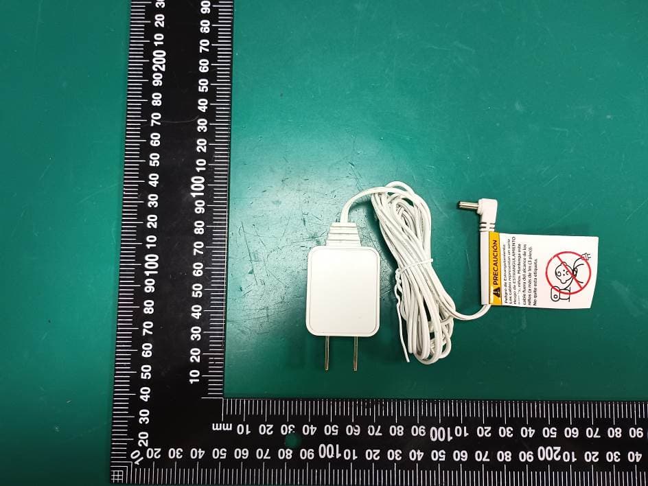
2ARRB-AM21APU
Nov 24, 2025Digital Audio Baby Monitor
Equipment Class
PUT - Part 15 Unlicensed PCS portable Tx worn on body