2ARRE-GD501Digital Portable Radio
GOCOM Technology Co.,Ltd.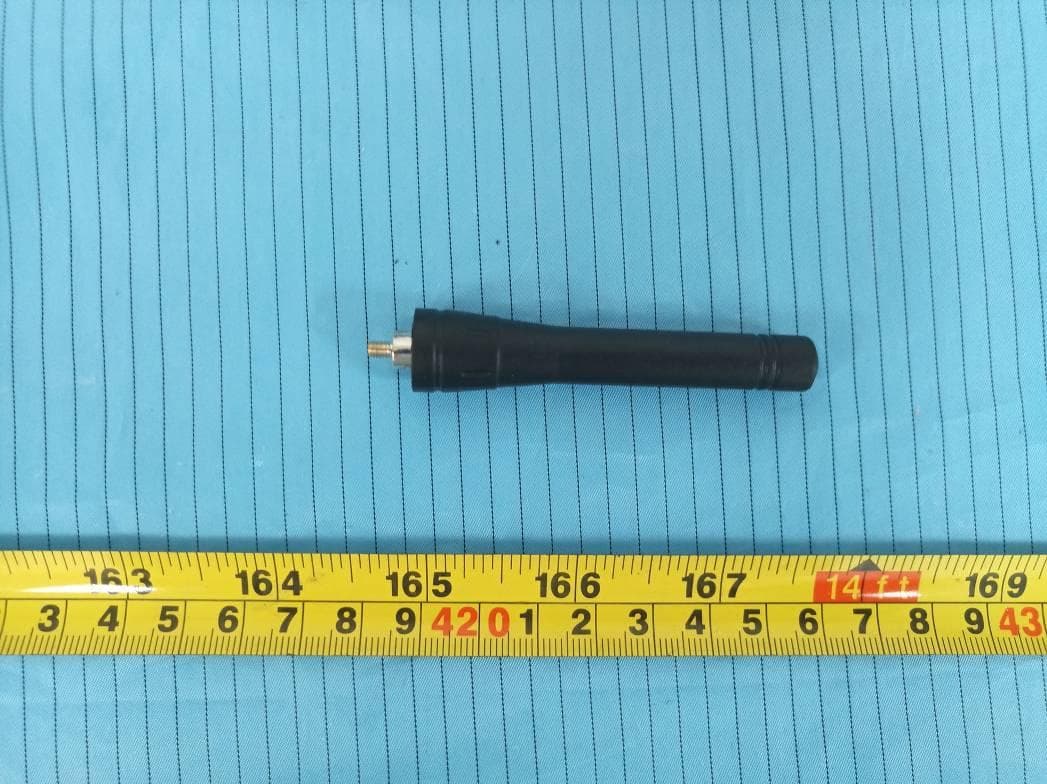
Click to zoom
Application Details
- Equipment Class
- TNF - Licensed Non-Broadcast Transmitter Held to Face
- Date of Grant
- Jun 22, 2020
- Application Purpose
- Original Equipment
- Date of Application
- Jun 22, 2020
- Equipment Note
- Digital Portable Radio
- Frequency Range
- 430.00000000 - 470.00000000
- Company
- GOCOM Technology Co.,Ltd.
- Country
- China
Documents & Files
Document Text
Text extracted from the exhibit documents filed with the FCC. Open a document above to read the original.
Users Manual
213 65(7) 335100427_RevA QUICK START GUIDE Digital Radio + 4 98 12 11 (13) 10 16 15 (17) 14 20 19 (21) 18 24 23 (25) 22 28 2726 TO USERS Thank you for purchasing out product! This Manual (contains both analog and digital radios) is designed to make you quickly grasp the use of the device. In order to avoid physical injury or property loss due to improper operation, please read this Manual carefully before using the device. NOTICE The device meets the requirements of FCC PART 90 and PART 15. Local laws and regulations shall be complied with when setting up or using the equipment, and corresponding qualifications and relevant procedures shall be obtained if necessary. Consulting the relevant authorities is suggested. This equipment has been tested and found to comply with the limits for a Class B digital device, pursuant to Part 15 of the FCC Rules. These limits are designed to provide reasonable protection against harmful interference in a residential installation. This equipment generates, uses and can radiate radio frequency energy and, if not installed and used in accordance with the instructions, may cause harmful interference to radio communications.However, there is no guarantee that interference will not occur in a particular installation. If this equipment does cause harmful interference to radio or television reception, which can be determined by turning the equipment off and on, the user is encouraged to try to correct the interference by one or more of the following measures: • Reorient or relocate the receiving antenna. • Increase the separation between the equipment and receiver. • Connect the equipment into an outlet on a circuit different from that to which the receiver is connected. • Consult the dealer or an experienced radio/TV technician for help. This device complies with Part 15 of the FCC Rules. Operation is subject to the following two conditions: 1. this device may not cause harmful interference, and. 2. this device must accept any interference received, including interference that may cause undesired operation. ISEDC RSS warning This product meets the applicable Industry Canada technical specifications. / Le présent matériel est conforme aux specifications techniques applicables d’Industrie Canada. SAFETY INFORMATION In order to use the radio safely and efficiently, please read the following safety information: • The radio can only be maintained by professional technicians. Do not disassemble the radio without permission. • Only the batteries and chargers specified by our company can be used. • To avoid problems caused by electromagnetic interference and electromagnetic compatibility, please turn off the radio in places where the "Please turn off the radio" sign is displayed, such as hospitals and other health care places. When taking the flight, please turn off the radio if the crew requests to do so. • In vehicles with airbags, do not place the radio in the area where airbag deployment may be involved. • Please turn off the radio before entering flammable or explosive environment. • Do not replace or charge the battery in a flammable or explosive environment. • Please turn off the radio before approaching the blasting area and the detonator area. • Do not use the radio with damaged antenna. A damaged antenna may cause minor burns when it comes into contact with the skin. • Do not expose the radio to direct sunlight for a long time or place it near the heating Radio. • If you wear a portable radio, make sure the antenna is at least 2.5 cm away from your body when the radio is transmitting. WARNING: Changes or modifications to this unit not expressly approved by the party responsible for compliance could void the user’s authority to operate the equipment. CAUTION: Use the approved charger to charge the battery. The remaining lithium-ion battery is limited to 30% pursuant to the new lithium battery shipment regulation approved by International Air Transport Association (IATA). Before use, charge the battery. It is recommended that the radio remain powered off during charging. Use of battery not recommend or replaced with incorrect type of battery may result in a risk of fire and explosion or personal injury. Maximum ambient temperature around the power supply equipment including charger must not exceed 40(104ºF) and device operating temperature not exceed 55 (131ºF). RF Exposure Compliance and Control Guidelines and Operating Instructions To control your exposure and ensure compliance with the occupational/controlled environment exposure limits always adhere to the following procedures. Guidelines: • Do not remove the RF Exposure Label from the device. • User awareness instructions should accompany device when transferred to other users. • Do not use this device if the operational requirements described herein are not met. Operating Instructions: • Transmit no more than the rated duty factor of 50% of the time. To transmit (talk), push the Push-To-Talk (PTT) button. To receive calls, release the PTT button. Transmit- ting 50 % of the time, or less, is important because this radio generates measurable RF energy exposure only when transmitting (in terms of measuring for standards compliance). • Hold the radio in a vertical position in front of face with the microphone (and the other parts of the radio, including the antenna) at least one inch (2.5 cm) away from the nose. Keeping the radio at the proper distance is important because RF exposures decrease with distance from the antenna. Antenna should be kept away from eyes. • When worn on the body, always place the radio in approved clip, holder, holster, case, or body harness for this product. Using approved body-worn accessories is important because the use other manufacturer’s non-approved accessories may result in exposure levels, which exceed the occupational/controlled environment RF exposure limits. • If you are not using a body-worn accessory and are not using the radio in the intended use position in front of…
Text truncated - open the document above for the full version.
Attestation Statements
GOCOM Technology Co.,Ltd. UNIT12, 14/F, LIPPO SUN PLAZA,28 CANTON ROAD TSIM SHA TSUI, KOWLOON, Hong Kong, China Tel: +8618750555801 Email: [email protected] Fax: 0085223744662 Date: 2020-05-26 To: FEDERAL COMMUNICATIONS COMMISSIONS Authorization and Evaluation Division 7435 Oakland Mills Road Columbia, MD 21046 Subject: Attestation statement regarding the Digital Portable Radio spectrum efficiency TYPE OF EQUIPMENT: Digital Portable Radio Model number: GD501 FCC ID: 2ARRE-GD501 Dear Sir or Madam We, GOCOM Technology Co.,Ltd. declare that the time division multiple access (TDMA) technology provides two paths in a 12.5 kHz channel bandwidth, thus meeting the one voice path per 6.25 kHz of spectrum requirement. This radio also provides data rate of 9600 bps in a 12.5 kHz channel, thus meeting the minimum data rate of 4800 bps in a 6.25 kHz channel. Please contact the undersigned if you have any questions or need any further information. Sincerely, Signature Snow Huang Sales Executive
Cover Letter(s)
GOCOM Technology Co.,Ltd. UNIT12, 14/F, LIPPO SUN PLAZA,28 CANTON ROAD TSIM SHA TSUI, KOWLOON, Hong Kong, China Tel: +8618750555801 Email: [email protected] Fax: 0085223744662 Date: 2020-05-26 Product Similarity Declaration To Whom It May Concern, We, GOCOM Technology Co.,Ltd. hereby declare that we have a product named as Digital Portable Radio (Model number: GD501, FCC ID: 2ARRE-GD501, IC: 24523-GD501) was tested by BACL, meanwhile, for our marketing purpose, we would like to list a series models (GD300) on reports and certificate, all the models are identical schematics, shell thickness and shell size are same, just appearance pattern is different as below picture showed. No other changes are made to them. We confirm that all information above is true, and we’ll be responsible for all the consequences. Please contact with me if you have any question. Sincerely, Signature: Snow Huang Sales Executive
External Photos
EXHIBIT B - EUT EXTERNAL PHOTOGRAPHS Antenna Charger
ID Label/Location Info
EXHIBIT A - FCC ID LABEL AND LOCATION Label 1 Label 2 FCC ID Label Location Information The label shown shall be permanently affixed at a conspicuous location on the device and be readily visible to the user at the time purchase (Labeling requirements per 2.925) Label 1 Label 2
Internal Photos
EXHIBIT C - EUT INTERNAL PHOTOGRAPHS
RF Exposure Info
Note: This test report is prepared for the customer shown above and for the device described herein. It may not be duplicated or used in part without prior written consent from Bay Area Compliance Laboratories Corp. (Dongguan). This report must not be used by the customer to claim product certification, approval, or endorsement by A2LA* or any agency of the Federal Government. * This report may contain data that are not covered by the A2LA accreditation and are marked with an asterisk “*”. SAR EVALUATION REPORT For GOCOM Technology Co., Ltd. UNIT 12, 14/F, LIPPO SUN PLAZA, 28 CANTON ROAD TSIM SHA TSUI, KOWLOON, Hong Kong, China FCC ID: 2ARRE-GD501 Report Type: Original Report Product Type: Digital Portable Radio Report Number: RSZ200427811-20A Report Date: 2020-05-20 Reviewed By: Rocky Xiao RF Engineer Prepared By: Bay Area Compliance Laboratories Corp. (Dongguan) No.69 Pulongcun, Puxinhu Industry Area, Tangxia, Dongguan, Guangdong, China Tel: +86-769-86858888 Fax: +86-769-86858891 www.baclcorp.com.cn Bay Area Compliance Laboratories Corp. (Dongguan) Report No.: RSZ200427811-20A SAR Evaluation Report 2 of 31 Attestation of Test Results EUT Information EUT Description Digital Portable Radio Tested Model GD501 Multiple Model GD300 FCC ID 2ARRE-GD501 Serial Number RSZ200427811-SA-S1 Test Date 2020-04-28 Mode Test Model Max. SAR Level(s) Reported(W/kg) Limit PTT (430-470MHz) 1g Head SAR(Face Up) 1.35 8.0 (W/kg) 1g Body SAR(Body Back)1.92 Applicable Standards FCC 47 CFR part 2.1093 Radiofrequency radiation exposure evaluation: portable devices IEEE1528:2013 IEEE Recommended Practice for Determining the Peak Spatial-Average Specific Absorption Rate (SAR) in the Human Head from Wireless Communications Devices: Measurement Techniques RF Exposure Procedures: TCB Workshop April 2019 IEC 62209-1:2016 Measurement procedure for the assessment of specific absorption rate of human exposure to radio frequency fields from hand-held and body-mounted wireless communication devices – Part 1: Devices used next to the ear (Frequency range of 300 MHz to 6 GHz) KDB procedures KDB 447498 D01 General RF Exposure Guidance v06 KDB 865664 D01 SAR Measurement 100 MHz to 6 GHz v01r04 KDB 865664 D02 RF Exposure Reporting v01r02 KDB 643646 D01 SAR Test for PTT Radios v01r03 Note: This wireless device has been shown to be capable of compliance for localized specific absorption rate (SAR) for Occupational/Controlled Exposure limits specified in FCC 47 CFR part 2.1093 and has been tested in accordance with the measurement procedures specified in IEEE 1528-2013 and RF exposure KDB procedures. The results and statements contained in this report pertain only to the device(s) evaluated. Bay Area Compliance Laboratories Corp. (Dongguan) Report No.: RSZ200427811-20A SAR Evaluation Report 3 of 31 TABLE OF CONTENTS DOCUMENT REVISION HISTORY ......................................................................................................................... 4 EUT DESCRIPTION .................................................................................................................................................... 5 TECHNICAL SPECIFICATION ......................................................................................................................................... 5 REFERENCE, STANDARDS, AND GUIDELINES .................................................................................................. 6 SAR LIMITS ................................................................................................................................................................. 6 FACILITIES .................................................................................................................................................................. 7 DESCRIPTION OF TEST SYSTEM .......................................................................................................................... 8 EQUIPMENT LIST AND CALIBRATION ............................................................................................................. 13 EQUIPMENTS LIST & CALIBRATION INFORMATION .................................................................................................... 13 SAR MEASUREMENT SYSTEM VERIFICATION .............................................................................................. 14 LIQUID VERIFICATION ............................................................................................................................................... 14 SYSTEM ACCURACY VERIFICATION ........................................................................................................................... 15 SAR SYSTEM VALIDATION DATA ..................................................................................................................... 16 EUT TEST STRATEGY AND METHODOLOGY ................................................................................................. 17 TEST POSITIONS FOR DEVICE OPERATING NEXT TO A PERSON’S EAR........................................................................ 17 CHEEK/TOUCH POSITION ........................................................................................................................................... 18 EAR/TILT POSITION ................................................................................................................................................... 18 TEST POSITIONS FOR BODY-WORN AND OTHER CONFIGURATIONS .............................................................................. 19 TEST DISTANCE FOR SAR EVALUATION .................................................................................................................... 19 SAR EVALUATION PROCEDURE ................................................................................................................................. 20 CONDUCTED OUTPUT POWER MEASUREMENT ............................................................................…
Text truncated - open the document above for the full version.
RF Exposure Info
Report No.: RSZ200427811-20A SAR Plots Plot 1# Test Plot 1#: FM_12.5kHz_469.9875MHz_Face Up DUT: Digital Portable Radio; Type: GD501; Serial: RSZ200427811-SA-S1 Communication System: FM; Frequency: 469.988 MHz;Duty Cycle: 1:1 Medium parameters used: f = 469.988 MHz; σ = 0.892 S/m; ε r = 44.196; ρ = 1000 kg/m 3 Phantom section: Flat Section DASY5 Configuration: Probe: ES3DV2 - SN3019; ConvF(7.02, 7.02, 7.02) @ 469.988 MHz; Calibrated: 2019/9/25 Sensor-Surface: 4mm (Mechanical Surface Detection) Electronics: DAE3 Sn471; Calibrated: 2019/12/25 Phantom: ELI v8.0; Type: QDOVA004AA; Serial: 2051 Measurement SW: DASY52, Version 52.10 (2); SEMCAD X Version 14.6.12 (7470) Area Scan (71x131x1): Interpolated grid: dx=1.500 mm, dy=1.500 mm Maximum value of SAR (interpolated) = 2.85 W/kg Zoom Scan (5x5x7)/Cube 0: Measurement grid: dx=8mm, dy=8mm, dz=5mm Reference Value = 55.11 V/m; Power Drift = -0.12 dB Peak SAR (extrapolated) = 3.37 W/kg SAR(1 g) = 2.58 W/kg; SAR(10 g) = 1.94 W/kg Maximum value of SAR (measured) = 2.71 W/kg 0 dB = 2.71 W/kg = 4.33 dBW/kg Report No.: RSZ200427811-20A SAR Plots Plot 2# Test Plot 2#: 4FSK_469.9875MHz_Face Up DUT: Digital Portable Radio; Type: GD501; Serial: RSZ200427811-SA-S1 Communication System: 4FSK; Frequency: 469.988 MHz;Duty Cycle: 1:2 Medium parameters used: f = 469.988 MHz; σ = 0.892 S/m; ε r = 44.196; ρ = 1000 kg/m 3 Phantom section: Flat Section DASY5 Configuration: Probe: ES3DV2 - SN3019; ConvF(7.02, 7.02, 7.02) @ 469.988 MHz; Calibrated: 2019/9/25 Sensor-Surface: 4mm (Mechanical Surface Detection) Electronics: DAE3 Sn471; Calibrated: 2019/12/25 Phantom: ELI v8.0; Type: QDOVA004AA; Serial: 2051 Measurement SW: DASY52, Version 52.10 (2); SEMCAD X Version 14.6.12 (7470) Area Scan (71x121x1): Interpolated grid: dx=1.500 mm, dy=1.500 mm Maximum value of SAR (interpolated) = 1.68 W/kg Zoom Scan (5x5x7)/Cube 0: Measurement grid: dx=8mm, dy=8mm, dz=5mm Reference Value = 40.84 V/m; Power Drift = -0.06 dB Peak SAR (extrapolated) = 2.10 W/kg SAR(1 g) = 1.5 W/kg; SAR(10 g) = 1.12 W/kg Maximum value of SAR (measured) = 1.58 W/kg 0 dB = 1.58 W/kg = 1.99 dBW/kg Report No.: RSZ200427811-20A SAR Plots Plot 3# Test Plot 3#: FM_12.5kHz_430.0125MHz_Body Back DUT: Digital Portable Radio; Type: GD501; Serial: RSZ200427811-SA-S1 Communication System: FM; Frequency: 430.012 MHz;Duty Cycle: 1:1 Medium parameters used: f = 430.012 MHz; σ = 0.861 S/m; ε r = 44.878; ρ = 1000 kg/m 3 Phantom section: Flat Section DASY5 Configuration: Probe: ES3DV2 - SN3019; ConvF(7.02, 7.02, 7.02) @ 430.012 MHz; Calibrated: 2019/9/25 Sensor-Surface: 4mm (Mechanical Surface Detection) Electronics: DAE3 Sn471; Calibrated: 2019/12/25 Phantom: ELI v8.0; Type: QDOVA004AA; Serial: 2051 Measurement SW: DASY52, Version 52.10 (2); SEMCAD X Version 14.6.12 (7470) Area Scan (71x131x1): Interpolated grid: dx=1.500 mm, dy=1.500 mm Maximum value of SAR (interpolated) = 2.55 W/kg Zoom Scan (5x5x7)/Cube 0: Measurement grid: dx=8mm, dy=8mm, dz=5mm Reference Value = 55.22 V/m; Power Drift = -0.19 dB Peak SAR (extrapolated) = 2.76 W/kg SAR(1 g) = 2.09 W/kg; SAR(10 g) = 1.56 W/kg Maximum value of SAR (measured) = 2.19 W/kg 0 dB = 2.19 W/kg = 3.40 dBW/kg Report No.: RSZ200427811-20A SAR Plots Plot 4# Test Plot 4#: FM_12.5kHz_440.0125MHz_Body Back DUT: Digital Portable Radio; Type: GD501; Serial: RSZ200427811-SA-S1 Communication System: FM; Frequency: 440.012 MHz;Duty Cycle: 1:1 Medium parameters used: f = 440.012 MHz; σ = 0.865 S/m; ε r = 44.531; ρ = 1000 kg/m 3 Phantom section: Flat Section DASY5 Configuration: Probe: ES3DV2 - SN3019; ConvF(7.02, 7.02, 7.02) @ 440.012 MHz; Calibrated: 2019/9/25 Sensor-Surface: 4mm (Mechanical Surface Detection) Electronics: DAE3 Sn471; Calibrated: 2019/12/25 Phantom: ELI v8.0; Type: QDOVA004AA; Serial: 2051 Measurement SW: DASY52, Version 52.10 (2); SEMCAD X Version 14.6.12 (7470) Area Scan (71x131x1): Interpolated grid: dx=1.500 mm, dy=1.500 mm Maximum value of SAR (interpolated) = 2.94 W/kg Zoom Scan (5x5x7)/Cube 0: Measurement grid: dx=8mm, dy=8mm, dz=5mm Reference Value = 57.72 V/m; Power Drift = -0.16 dB Peak SAR (extrapolated) = 3.51 W/kg SAR(1 g) = 2.69 W/kg; SAR(10 g) = 2.02 W/kg Maximum value of SAR (measured) = 2.83 W/kg 0 dB = 2.83 W/kg = 4.52 dBW/kg Report No.: RSZ200427811-20A SAR Plots Plot 5# Test Plot 5#: FM_12.5kHz_450.0125MHz_Body Back DUT: Digital Portable Radio; Type: GD501; Serial: RSZ200427811-SA-S1 Communication System: FM; Frequency: 450.012 MHz;Duty Cycle: 1:1 Medium parameters used: f = 450.012 MHz; σ = 0.882 S/m; ε r = 44.363; ρ = 1000 kg/m 3 Phantom section: Flat Section DASY5 Configuration: Probe: ES3DV2 - SN3019; ConvF(7.02, 7.02, 7.02) @ 450.012 MHz; Calibrated: 2019/9/25 Sensor-Surface: 4mm (Mechanical Surface Detection) Electronics: DAE3 Sn471; Calibrated: 2019/12/25 Phantom: ELI v8.0; Type: QDOVA004AA; Serial: 2051 Measurement SW: DASY52, Version 52.10 (2); SEMCAD X Version 14.6.12 (7470) Area Scan (71x131x1): Interpolated grid: dx=1.500 mm, dy=1.500 mm Maximum value of SAR (interpolated) = 3.86 W/kg Zoom Scan (5x5x7)/Cube 0: Measurement grid: dx=8mm, dy=8mm, dz=5mm Reference Value = 66.35 V/m; Power Drift = -0.17 dB Peak SAR (extrapolated) = 4.34 W/kg SAR(1 g) = 3.29 W/kg; SAR(10 g) = 2.46 W/kg Maximum value of SAR (measured) = 3.46 W/kg 0 dB = 3.46 W/kg = 5.39 dBW/kg Report No.: RSZ200427811-20A SAR Plots Plot 6# Test Plot 6#: FM_12.5kHz_459.9875MHz_Body Back DUT: Digital Portable Radio; Type: GD501; Serial: RSZ200427811-SA-S1 Communication System: FM; Frequency: 459.988 MHz;Duty Cycle: 1:1 Medium parameters used: f = 459.988 MHz; σ = 0.887 S/m; ε r = 44.243; ρ = 1000 kg/m 3 Phantom section: Flat Section DASY5 Configuration: Probe: ES3DV2 - SN3019; ConvF(7.02, 7.02, 7.02) @ 459.988 MHz; Calibrated: 2019/9/25 Sensor-Surface: 4mm (Mechanical Surface Detection) Electronics: DAE3 Sn471; Calibrated: 2019/12/25 Phantom: ELI v8.0; Type: QDOVA004AA; Serial: 2051 Measurement SW: DASY52, Version 52.10 (2…
Text truncated - open the document above for the full version.
RF Exposure Info
Report No.: RSZ200427811-20A Page 1 of 2 APPENDIX B EUT TEST POSITION PHOTOS Liquid depth ≥ 15cm Report No.: RSZ200427811-20A Page 2 of 2 Face Up Setup Photo(25mm) Body Back Setup Photo(0mm) 45mm 12mm 25mm
Test Report
Note: This report must not be used by the customer to claim product certification, approval, or endorsement by A2LA* or any agency of the Federal Government. This report may contain data that are not covered by the A2LA accreditation and are marked with an asterisk “★”. BACL is not responsible for the authenticity of any test data provided by the applicant. Data included from the applicant that may affect test results are marked with an asterisk ’*’. Customer model name, addresses, names, trademarks etc. are not considered data. This report cannot be reproduced except in full, without prior written approval of the Company. Unless otherwise stated the results shown in this test report refer only to the sample(s) tested. This report is valid only with a valid digital signature. The digital signature may be available only under the Adobe software above version 7.0. FCC PART 90 TEST REPORT For GOCOM Technology Co.,Ltd. UNIT 12, 14/F, LIPPO SUN PLAZA, 28 CANTON ROAD TSIM SHA TSUI, KOWLOON, Hong Kong, China FCC ID: 2ARRE-GD501 R e p o r t T y p e : O r i gi n a l R e p o r t P r o d u c t T y p e : D i gi t a l P o r t a b l e R a d i o Report Number: RSZ200427811-00 Report Date: 2020-06-02 Reviewed By: Jimmy Xiao RF Engineer Prepared By: Bay Area Compliance Laboratories Corp. (Shenzhen) 6/F., West Wing, Third Phase of Wanli Industrial Building, Shihua Road, Futian Free Trade Zone, Shenzhen, Guangdong, China Tel: +86-755-33320018 Fax: +86-755-33320008 www.baclcorp.com.cn Bay Area Compliance Laboratories Corp. (Shenzhen) Report No.: RSZ200427811-00A FCC Part 90 Page 2 of 33 TABLE OF CONTENTS GENERAL INFORMATION ....................................................................................................................................... 4 PRODUCT DESCRIPTION FOR EQUIPMENT UNDER TEST (EUT) ..................................................................................... 4 OBJECTIVE ................................................................................................................................................................... 4 RELATED SUBMITTAL(S)/GRANT(S) ............................................................................................................................. 4 TEST METHODOLOGY .................................................................................................................................................. 4 MEASUREMENT UNCERTAINTY .................................................................................................................................... 5 TEST FACILITY ............................................................................................................................................................. 5 SYSTEM TEST CONFIGURATION .......................................................................................................................... 6 DESCRIPTION OF TEST CONFIGURATION ...................................................................................................................... 6 EUT EXERCISE SOFTWARE .......................................................................................................................................... 6 SPECIAL ACCESSORIES ................................................................................................................................................. 6 EQUIPMENT MODIFICATIONS ....................................................................................................................................... 6 SUPPORT EQUIPMENT LIST AND DETAILS .................................................................................................................... 6 BLOCK DIAGRAM OF TEST SETUP ................................................................................................................................ 6 SUMMARY OF TEST RESULTS ............................................................................................................................... 7 TEST EQUIPMENT LIST ........................................................................................................................................... 8 FCC §1.1307(b) & §2.1093 - RF EXPOSURE INFORMATION .............................................................................. 9 APPLICABLE STANDARD .............................................................................................................................................. 9 TEST RESULT ............................................................................................................................................................... 9 FCC §2.1046 & §90.205 - RF OUTPUT POWER .................................................................................................... 10 APPLICABLE STANDARD ............................................................................................................................................ 10 TEST PROCEDURE ...................................................................................................................................................... 10 TEST DATA ................................................................................................................................................................ 10 FCC §2.1047 & §90.207 - MODULATION CHARACTERISTIC .......................................................................... 12 APPLICABLE STANDARD ............................................................................................................................................ 12 TEST PROCEDURE ...................................................................................................................................................... 12 TEST DATA ................................................................................................................................................................ 12 FCC §2.1049 & §90.210 – OCCUPIED BANDWIDTH & EMISSION MASK ..............…
Text truncated - open the document above for the full version.
Contact Information
Applicant
Snow Huang(Sales Executive)
Test Firm
Bay Area Compliance Laboratories Corp. (Shenzhen)Well Wang
[email protected]+86 (0) 755 33320018
Technical Specifications
| # | Rule Parts | Frequency Range | Power Output | Emission | Tolerance |
|---|---|---|---|---|---|
| 3 | 9 | 430 MHz - 470 MHz | 2 W | 7K60F1E | 2.5 ppm |
Other Applications from GOCOM Technology Co.,Ltd.

2ARRE-2020G125
Feb 09, 2021walkie talkie
Equipment Class
JAB - Part 15 Class B Digital Device
2ARRE-2020GA10
Feb 03, 2021walkie talkie
Equipment Class
FRF - Part 95 Family Radio Face Held Transmitter
2ARRE-2020GA70
Feb 03, 2021walkie talkie
Equipment Class
FRF - Part 95 Family Radio Face Held Transmitter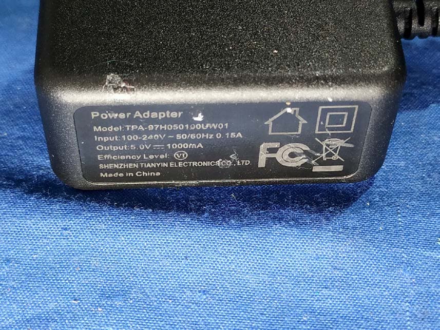
2ARRE-2020GA80
Feb 01, 2021walkie talkie
Equipment Class
JAB - Part 15 Class B Digital Device
2ARRE-2020G150
Jan 28, 2021walkie talkie
Equipment Class
FRF - Part 95 Family Radio Face Held Transmitter