2ASJR-CM25-1113120Wireless Tracking Cargo System
Globetracker, ApSApplication Details
- Equipment Class
- DTS - Digital Transmission System
- Date of Grant
- Nov 08, 2022
- Application Purpose
- Original Equipment
- Date of Application
- Nov 08, 2022
- Equipment Note
- Wireless Tracking Cargo System
- Frequency Range
- 2402.00000000 - 2480.00000000
- Company
- Globetracker, ApS
- Country
- Denmark
Documents & Files
Document Text
Text extracted from the exhibit documents filed with the FCC. Open a document above to read the original.
Users Manual
04/03/2019, 15.21 Installation Guide Carrier – NaturaLINE, PrimeLINE, ThinLINE, EliteLINE 04/03/2019, 15.21 ! 1. Electrical Ratings and Requirements Product Supply Ratings Power Supply: 18-36 VAC 50-60 Hz or 12-36 VDC, 2A WARNING These procedures should only be performed by trained installation technicians. High voltage/current lines are present and caution should be used to prevent injuries. Installer must conform to local standards and ordinances as required. IMPORTANT Make sure that power is off, unit is disconnected and that no damages have occurred during drilling. 04/03/2019, 15.21 2. Required Tool Kit 13mm (1/2 “) Drill Bit Center Punch Cutting compound for the drill Drill for removing burrs Degreasing rags 18mm open face wrench Side cutting pliers Magnet Cable Ties 04/03/2019, 15.21 3. GT Sense Reefer Kit A complete GT Sense Reefer Kit includes: 1. GT Sense Device 2. Antenna (80 mm diameter round black version with 3M VHB tape and threaded mount on the back cables and connectors 3. RMM Cable . 04/03/2019, 15.21 4. RMM Bracket 04/03/2019, 15.21 5. Installation Before beginning the antenna installation, please print and cut out the template to use for locating the antenna mounting hole. Step 1 Use the antenna installation template to locate the antenna placement on the access cover. Place the template towards the edge of the access cover and mark the center point. Check that there is nothing on the inside surface of the access cover that could be damaged when a hole is drilled in the centre-punched location. NOTE: Avoid blocking the information labels. NOTE: If an antenna by another company is already mounted, DO NOT remove it. 04/03/2019, 15.21 Step 2 Drill a 13 mm (1/2′′) hole at the centre-punched mark. Remove all burrs after drilling. Step 3 Degrease/clean the surface where the antenna will be mounted with a metal cleaner or similar before fitting the antenna. 04/03/2019, 15.21 Step 4 Remove the nut, lock washer, and plastic washer from the threaded mount on the backside of the antenna by slipping them off the antenna cable via the slots. Step 5 Insert the connector end of the antenna cable through the drilled hole in the access cover. Remove the 3M VHB table liner from the backside of the antenna. Push the thread mount through the drilled hole and secure the antenna cables. Note: Specific orientation/rotation of the antenna is not required. Step 6 Replace the plastic washer, lock washer and nut on the antenna threaded mount on the inside of the access cover. Tighten the nut firmly with the 18mm open face wrench, torque to 1.5 N-m (11.5 in-lbs). 04/03/2019, 15.21 Step 7 Remove the access plug from side of control box. Cut a hole in the plug and run cables trough. Seal with silicone. Step 8 If a modem is already present in the RMM slot, remove it maintaining the Mounting screws and unplug all the connections 04/03/2019, 15.21 Step 9 Route the antenna cables across the door hinge through existing cable channel (if present) to the RMM slot using the cable ties to secure the cables. Do not be concerned with the extra length of cable at this time. Step 10 Fit the GT Sense Device into the RMM slot and secure with the screws from the removed modem. If no modem was removed, use the M5 screws and mylar washers provide in the RMM bracket kit. Insert GT Sense and slide down and lock in place 04/03/2019, 15.21 Step 11 Connect and secure the antenna cables to appropriate Farkas connectors on the GT Sense Device before connecting the RMM cable to the The antenna cables are identified by labels near the connector ends. The corresponding Farkas connectors on the GT Sense Device are identified with the names “GPS” and “CELL”. After connecting the antenna cables, attach the RMM cable to the mating connector on the GT Sense Device and secure with the screws provided on the connector. Step 12 Plug the 3 and 7 position connector into the orange 10 position connector on the end of the GT RMM Cable as indicated by the 3/7 label on the 10 position connector. If the RMM Cable you are installing has an inline fuse, the fuse is intended to be 04/03/2019, 15.21 on the Ground Line for A/C reverse polarity protection for the GT Sense Device. Orange Connector on CBL0037 GT RMM Cable The 3 and 7 position connector plugged into the orange 10 position connector. Step 13 Secure any extra length of antenna cable or RMM cable with cable ties making sure not cables are in tension. Step 14 Secure the control box door. Step 15 Use the Installation app to verify GPS and communications are working (future). Installation complete. FCC/CE Compliance FCC Warning This device complies with part 15 of the FCC Rules. Operation is subject to the following two conditions: (1) this device may not cause harmful interference, and (2) this device must accept any interference received, including interference that may cause undesired operation. Any changes or modifications not expressly approved by the party responsible for compliance could void the user’s authority to operate the equipment. NOTE: This equipment has been tested and found to comply with the limits for a Class B digital device, pursuant to Part 15 of the FCC Rules. These limits are designed to provide reasonable protection against harmful interference in a residential installation. This equipment generates, uses and can radiate radio frequency energy and, if not installed and used in accordance with the instructions, may cause harmful interference to radio communications. However, there is no guarantee that interference will not occur in a particular installation. If this equipment does cause harmful interference to radio or television reception, which can be determined by turning the equipment off and on, the user is encouraged to try to correct the interference by one or more of the following measures: Reorient or relocate the receiving antenna. Increase the separation between the equipment and receiver. Connect the equipment into an outlet on a circuit different fro…
Text truncated - open the document above for the full version.
Cover Letter(s)
7/19/2021 Federal Communications Commission Authorization & Evaluation Division 7345 Oakland Mills Road Columbia, Maryland 21046 RE: LETTER OF AGENT AUTHORIZATION To Whom It May Concern: We, the undersigned, hereby authorize Compliance Testing, LLC to act on our behalf in all matters relating to application for equipment authorization, including the signing of all documents relating to these matters. We also hereby certify that no party to the application authorized hereunder is subject to the denial of benefits, including FCC benefits, pursuant to Section 5301 of the Anti-Drug Abuse Act of 1988, 21 U.S.C.853(a). Sincerely, Mark P Oudshoorn Director of Engineering Globetracker. ApS. Strandgade 91, 4 th Floor DK-1401 Copenhagen K Denmark
Cover Letter(s)
7/21/2021 Federal Communications Commission Authorization & Evaluation Division 7345 Oakland Mills Road Columbia, Maryland 21046 RE: Long-Term Confidentiality Request for G2.5 Telematics – CM2.5-1113120 – 2ASJR To Whom It May Concern: This letter serves as an official request for confidentiality under § 0.457(d) and § 0.459 of CFR 47. We have requested that the following documents required to be submitted with this application be permanently withheld from public review. Block Diagram Schematics Theory of Operation Parts List/BOM These documents contain detailed system and equipment descriptions and related information about the product, which manufacturer/applicant considers to be proprietary, confidential, and a custom design and otherwise, would not release to the general public. Since this design is a basis from which future technological products will evolve, manufacturer/applicant feels that this information would be of benefit to its competitors, and that the disclosure of the information in these documents would give our competitors an unfair advantage in the market. Please contact me if there is any information you may need. Sincerely, Mark Oudshoorn Director of Engineering Globetracker ApS. Strandgade 91, 4 th Floor DK-1401 Copenhagen K Denmark
Cover Letter(s)
7/21/2021 Federal Communications Commission Authorization & Evaluation Division 7345 Oakland Mills Road Columbia, Maryland 21046 Subject: Short-Term Confidentiality Request for: 2ASJR-CM2.5-1113120 To Whom It May Concern: In accordance with sections 0.457 and 0.459 of CFR 47, Globetracker ApS. requests Short-Term Confidentiality for the following exhibits of this application for a period of 180 after grant is issued: Test setup photos External photos Internal photos User’s manual These documents contain detailed system and equipment descriptions and related information about the product, which manufacturer/applicant considers to be proprietary, confidential, and a custom design and otherwise, would not release to the general public. Since this design is a basis from which future technological products will evolve, manufacturer/applicant feels that this information would be of benefit to its competitors, and that the disclosure of the information in these documents would give our competitors an unfair advantage in the market. Grantee will not market or distribute product during the Short-Term Confidentiality period requested. When the device is ready to be marketed the grantee will inform the TCB to release the Short-Term Confidentiality. Please contact me if there is any information you may need. Sincerely, Mark P Oudshoorn Director of Engineering Globetracker. ApS. Strandgade 91, 4 th Floor DK-1401 Copenhagen K Denmark
ID Label/Location Info
S/N: 622130209 MODEL: CM2 5-1113120 Build: 0322 FCC Warning: This device complies with part 15 of the FCC Rules. Operation is subject to the following two conditions: (1) This device may not cause harmful interference and (2) this device must accept interference received, including that may cause undesired operation. FCC ID: 2ASJR-CM2 5-1113120 Manufacturer: Danchell Address: Lyngvej 8, DK4450 Jyderup Denmark Importer: Globe Tracker ApS Address: Strandgade 91, DK1401 Kobenhaven Denmark CONTAINS FFC ID:XMR201903EG25G GT Sense Input: 12V, 1.5A IMSI 1: 232031721416512 IMSI 2:
RF Exposure Info
Toll-free: (866) 311-3268 Fax: (480) 926-3598 www.ComplianceTesting.com [email protected] p2110001_FCC RF Exposure_Rev 1.0 Page 1 of 6 Test Report Prepared for: Globe Tracker EUT Name: G2.5 Cargo Container Tracking Device Model: CM2.5-1113120 FCC ID: 2ASJR-CM25-1113120 To FCC Part 2.1093 Date of Issue: October 19, 2022 On the behalf of the applicant: Globe Tracker, ApS Strandgade 91, 4 th floor DK-1401 Copenhagen K Denmark Attention of: Mark Oudshoorn, Director of Engineering Ph: 941-212-7960 Email: [email protected] Prepared By Compliance Testing, LLC 1724 S. Nevada Way Mesa, AZ 85204 (480) 926-3100 phone / (480) 926-3598 fax www.compliancetesting.com Project No: p2110001 Alex Macon Project Test Engineer This report may not be reproduced, except in full, without written permission from Compliance Testing All results contained herein relate only to the sample tested p2110001_FCC RF Exposure_Rev 1.0 Page 2 of 6 Test Report Revision History Revision Date Revised By Reason for Revision 1.0 October 19, 2022 Alex Macon Original Document p2110001_FCC RF Exposure_Rev 1.0 Page 3 of 6 ANAB Compliance Testing, LLC, has been accredited in accordance with the recognized International Standard ISO/IEC 17025:2017. This accreditation demonstrates technical competence for a defined scope and the operation of a laboratory quality management system (refer to the joint ISO-ILAC-IAF Communiqué dated January 2009). The tests results contained within this test report all fall within our scope of accreditation, unless noted below. Please refer to http://www.compliancetesting.com/labscope.html for current scope of accreditation. FCC Site Reg. #349717 IC Site Reg. #2044A-2 Non-accredited tests contained in this report: N/A p2110001_FCC RF Exposure_Rev 1.0 Page 4 of 6 EUT Description Product Marketing Name (PMN) Cargo Container Tracking Device Model CM2.5-1113120 Supported Cellular Bands LTE FDD Band 2 LTE FDD Band 4 LTE FDD Band 12 LTE FDD Band 25 LTE TDD Band 41 WCDMA Band 2 WCDMA Band 4 GSM Band 1900 Frequency Ranges 902 – 928 MHz, 2402-2480 MHz Technology Types LoRa, BLE, LTE, WCDMA, GSM Antennas Pk Gain (BLE) :+1.0 dBi Pk Gain (LoRa): -2.5 dBi Pk Gain (cellular): +2.5 dBi Maximum Conducted Output Power Cellular: 0.6012 W BLE: 3.499 mW LoRa:3.177 mW General Description of EUT and its intended use: The EUT is a cargo shipping container. It is powered by internal 12VDC battery p2110001_FCC RF Exposure_Rev 1.0 Page 5 of 6 RF Exposure Test Exemption for Single Source KDB 447498 D01 v07 DRAFT 20 April 2021 2.1.3 SAR-Based Exemption A more comprehensive exemption, considering a variable power threshold that depends on both the separation distance and power, is provided in §1.1307(b)(3)(ii)(B). This exemption is applicable to the frequency range between 300 MHz and 6 GHz, with test separation distances between 0.5 cm and 40 cm, and for all RF sources in fixed, mobile, and portable device exposure conditions. Accordingly, a RF source is considered an RF exempt device if its available maximum time-averaged (matched conducted) power or its effective radiated power (ERP), whichever is greater, are below a specified threshold. This exemption threshold was derived based on general population 1-g SAR requirements and is detailed in Appendix C. 47 CFR 1.1307(b)(3)(i)(B) The available maximum time-averaged power or effective radiated power (ERP), whichever is greater, is less than or equal to the threshold P th (mW) described in the following formula. This method shall only be used at separation distances (cm) from 0.5 centimeters to 40 centimeters and at frequencies from 0.3 GHz to 6 GHz (inclusive). P th is given by: p2110001_FCC RF Exposure_Rev 1.0 Page 6 of 6 Frequency (MHz) Distance (cm) ERP (mw) Threshold (mW) Margin Outcome 906 20 3.17 2040 0.007 Pass 2480 20 3.49 3060 0.006 Pass Conclusion EUT is exempt from evaluation, the maximum radiated power is less than the power threshold for exemption END OF TEST REPORT
Test Report
11/9/2022 Device Solutions Inc Page 1(3) Proprietary & Confidential http://www.device-solutions.com/ Phone/Fax: (919) 732-7872 GlobeTracker 2.5 Custom Antenna Gains Revision 0.1 W. Darden 21-Sep-2020 11/9/2022 Device Solutions Inc Page 2(3) Proprietary & Confidential http://www.device-solutions.com/ Phone/Fax: (919) 732-7872 Table of Contents 1 Test Facilities & Data ................................................................................... Error! Bookmark not defined. Revision History Rev Date Author Description 0.1 09-Nov-2022 W. Darden Document Start 1 Test Facilities & Data The GlobeTracker 2.5 device has two custom PCB trace style antennas, one for 900 ISM, and one for 2500 ISM. These antennas were swept for peak gain in a Satimo Chamber. Peak Gain Data for the 900 ISM Antenna 11/9/2022 Device Solutions Inc Page 3(3) Proprietary & Confidential http://www.device-solutions.com/ Phone/Fax: (919) 732-7872 Peak Gain Data for the 2500 ISM Antenna
Test Report
Toll-free: (866) 311-3268 www.ComplianceTesting.com [email protected] P2110001_FCC_Part 15.247_DTS_Rev 1.0 Page 1 of 30 Test Report Prepared for: Globe Tracker EUT Name: G2.5 Cargo Container Tracking Device Model: CM2.5-1113120 FCC ID: 2ASJR-CM25-1113120 To FCC Part 15.247 DTS ISED RSS-247 Issue 2 Date of Issue: September 20, 2022 On the behalf of the applicant: Globe Tracker, ApS Strandgade 91, 4 th floor DK-1401 Copenhagen K Denmark Attention of: Mark Oudshoorn, Director of Engineering Ph: 941-212-7960 Email: [email protected] Prepared By Compliance Testing, LLC 1724 S. Nevada Way Mesa, AZ 85204 (480) 926-3100 phone / (480) 926-3598 fax www.compliancetesting.com Project No: p2110001 Test Result: Pass Authorized By Alex Macon Sr Engineer This report may not be reproduced, except in full, without written permission from Compliance Testing. All results contained herein relate only to the sample tested. P2110001_FCC_Part 15.247_DTS_Rev 1.0 Page 2 of 30 Test Results Summary FCC 15.247 Specification RSS-247 Specification Test Name Pass, Fail, N/A Comments 15.247(b) Section 5.4(d) Peak Output Power Pass 15.247(d) Section 5.5 Conducted Spurious Emissions Pass 15.247(d), 15.209(a), 15.205 Section 5.5 Radiated Spurious Emissions Pass 15.247(d), 15.209(a), 15.205 Section 5.5 Emissions At Band Edges Pass 15.247(a)(2) Sections 5.2(a) Occupied Bandwidth Pass 15.247(e) Section 5.2(b) Transmitter Power Spectral Density Pass 15.207 RSS-GEN Section 8.8 A/C Powerline Conducted Emissions N/A Unit operates on battery with no provision to connect to the AC Mains utility Statements of conformity are reported as: • Pass - the measured value is below the acceptance limit, acceptance limit = test limit. • Fail - the measured value is above the acceptance limit, acceptance limit = test limit. P2110001_FCC_Part 15.247_DTS_Rev 1.0 Page 3 of 30 Test Report Revision History Revision Date Revised By Reason for Revision 1.0 9/22/2022 Alex Macon Original Document P2110001_FCC_Part 15.247_DTS_Rev 1.0 Page 4 of 30 Table of Contents Description Page Test Results Summary .......................................................................................................................................................... 2 Standard Test Conditions Engineering Practices .................................................................................................................. 7 Peak Output Power ................................................................................................................................................................ 9 Occupied Bandwidth ............................................................................................................................................................ 12 Transmitter Power Spectral Density (PSD) ......................................................................................................................... 14 Conducted Spurious Emission ............................................................................................................................................. 17 Radiated Spurious Emissions .............................................................................................................................................. 19 Emissions at Band Edges .................................................................................................................................................... 28 Test Equipment Utilized ....................................................................................................................................................... 30 P2110001_FCC_Part 15.247_DTS_Rev 1.0 Page 5 of 30 ANAB Compliance Testing, LLC, has been accredited in accordance with the recognized International Standard ISO/IEC 17025:2017. This accreditation demonstrates technical competence for a defined scope and the operation of a laboratory quality management system (refer to the joint ISO-ILAC-IAF Communiqué dated January 2009). The tests results contained within this test report all fall within our scope of accreditation, unless noted below. Please refer to http://www.compliancetesting.com/labscope.html for current scope of accreditation. FCC Site Reg. #349717 IC Site Reg. #2044A-2 P2110001_FCC_Part 15.247_DTS_Rev 1.0 Page 6 of 30 The applicant has been cautioned as to the following 15.21 - Information to User The user’s manual or instruction manual for an intentional radiator shall caution the user that changes or modifications not expressly approved by the party responsible for compliance could void the user’s authority to operate the equipment. 15.27(a) - Special Accessories Equipment marked to a consumer must be capable of complying with the necessary regulations in the configuration in which the equipment is marketed. Where special accessories, such as shielded cables and/or special connectors are required to enable an unintentional or intentional radiator to comply with the emission limits in this part, the equipment must be marketed with, i.e. shipped and sold with, those special accessories. However, in lieu of shipping or packaging the special accessories with the unintentional or intentional radiator, the responsible party may employ other methods of ensuring that the special accessories are provided to the consumer without an additional charge. Information detailing any alternative method used to supply the special accessories for a grant of equipment authorization or retained in the verification records, as appropriate. The party responsible for the equipment, as detailed in § 2.909 of this chapter, shall ensure that these special accessories are provided with the equipment. The instruction manual for such devices shall include appropriate instructions on the first page of text concerned with the installation of the device that these special accessories must be used with the device. It is the responsibility of the user to use the needed special accessories su…
Text truncated - open the document above for the full version.
Test Report
Toll-free: (866) 311-3268 www.ComplianceTesting.com [email protected] P2110001_FCC_Part 15.247_BLE_DTS_Rev 1.0 Page 1 of 28 Test Report Prepared for: Globe Tracker EUT Name: G2.5 Cargo Container Tracking Device Model: CM2.5-1113120 FCC ID: 2ASJR-CM25-1113120 To FCC Part 15.247 DTS ISED RSS-247 Issue 2 Date of Issue: October 19, 2022 On the behalf of the applicant: Globe Tracker, ApS Strandgade 91, 4 th floor DK-1401 Copenhagen K Denmark Attention of: Mark Oudshoorn, Director of Engineering Ph: 941-212-7960 Email: [email protected] Prepared By Compliance Testing, LLC 1724 S. Nevada Way Mesa, AZ 85204 (480) 926-3100 phone / (480) 926-3598 fax www.compliancetesting.com Project No: p2110001 Test Result: Pass Authorized By Alex Macon Sr Engineer This report may not be reproduced, except in full, without written permission from Compliance Testing. All results contained herein relate only to the sample tested. P2110001_FCC_Part 15.247_BLE_DTS_Rev 1.0 Page 2 of 28 Test Results Summary FCC 15.247 Specification RSS-247 Specification Test Name Pass, Fail, N/A Comments 15.247(b) Section 5.4(d) Peak Output Power Pass 15.247(d), 15.209(a), 15.205 Section 5.5 Radiated Spurious Emissions Pass 15.247(d), 15.209(a), 15.205 Section 5.5 Emissions At Band Edges Pass 15.247(a)(2) Sections 5.2(a) Occupied Bandwidth Pass 15.247(e) Section 5.2(b) Transmitter Power Spectral Density Pass 15.207 RSS-GEN Section 8.8 A/C Powerline Conducted Emissions N/A Unit operates on battery with no provision to connect to the AC Mains utility Statements of conformity are reported as: • Pass - the measured value is below the acceptance limit, acceptance limit = test limit. • Fail - the measured value is above the acceptance limit, acceptance limit = test limit. Test Report Revision History P2110001_FCC_Part 15.247_BLE_DTS_Rev 1.0 Page 3 of 28 Revision Date Revised By Reason for Revision 1.0 10/19/2022 Alex Macon Original Document P2110001_FCC_Part 15.247_BLE_DTS_Rev 1.0 Page 4 of 28 Table of Contents Description Page Test Results Summary ................................................................................................................................................2 Standard Test Conditions Engineering Practices...........................................................................................................7 Peak Output Power .....................................................................................................................................................9 Occupied Bandwidth ................................................................................................................................................. 12 Transmitter Power Spectral Density (PSD) ................................................................................................................. 16 Radiated Spurious Emissions .................................................................................................................................... 19 Emissions at Band Edges.......................................................................................................................................... 27 Test Equipment Utilized ............................................................................................................................................ 28 P2110001_FCC_Part 15.247_BLE_DTS_Rev 1.0 Page 5 of 28 ANAB Compliance Testing, LLC, has been accredited in accordance with the recognized International Standard ISO/IEC 17025:2017. This accreditation demonstrates technical competence for a defined scope and the operation of a laboratory quality management system (refer to the joint ISO-ILAC-IAF Communiqué dated January 2009). The tests results contained within this test report all fall within our scope of accreditation, unless noted below. Please refer to http://www.compliancetesting.com/labscope.html for current scope of accreditation. FCC Site Reg. #349717 IC Site Reg. #2044A-2 P2110001_FCC_Part 15.247_BLE_DTS_Rev 1.0 Page 6 of 28 The applicant has been cautioned as to the following 15.21 - Information to User The user’s manual or instruction manual for an intentional radiator shall caution the user that changes or modifications not expressly approved by the party responsible for compliance could void the user’s authority to operate the equipment. 15.27(a) - Special Accessories Equipment marked to a consumer must be capable of complying with the necessary regulations in the configuration in which the equipment is marketed. Where special accessories, such as shielded cables and/or special connectors are required to enable an unintentional or intentional radiator to comply with the emission limits in this part, the equipment must be marketed with, i.e. shipped and sold with, those special accessories. However, in lieu of shipping or packaging the special accessories with the unintentional or intentional radiator, the responsible party may employ other methods of ensuring that the special accessories are provided to the consumer without an additional charge. Information detailing any alternative method used to supply the special accessories for a grant of equipment authorization or retained in the verification records, as appropriate. The party responsible for the equipment, as detailed in § 2.909 of this chapter, shall ensure that these special accessories are provided with the equipment. The instruction manual for such devices shall include appropriate instructions on the first page of text concerned with the installation of the device that these special accessories must be used with the device. It is the responsibility of the user to use the needed special accessories supplied with the equipment. P2110001_FCC_Part 15.247_BLE_DTS_Rev 1.0 Page 7 of 28 Standard Test Conditions Engineering Practices Except as noted herein, the following conditions and procedures were observed during the testing: In accordance with ANSI C63.10-2013 and unless otherwise indica…
Text truncated - open the document above for the full version.
Contact Information
Applicant
Mark Oudshoorn(Engineer)
Technical Contact
Globetracker ApS.Mark Oudshoorn
[email protected]9412127960
1748 Independence Blvd. · Sarasota, Florida · United States
Test Firm
Compliance Testing, LLCMichael Schafer
[email protected]480-926-3100
Technical Specifications
| # | Rule Parts | Frequency Range | Power Output |
|---|---|---|---|
| 2 | 15C | 2.40 GHz - 2.48 GHz | 3.50 mW |
Other Applications from Globetracker, ApS
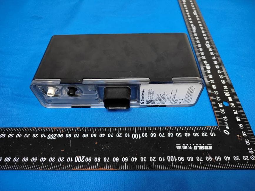
2ASJR-CM275-1113130
Dec 17, 2025Asset Tracking Device / Data Modem
Equipment Class
DTS - Digital Transmission System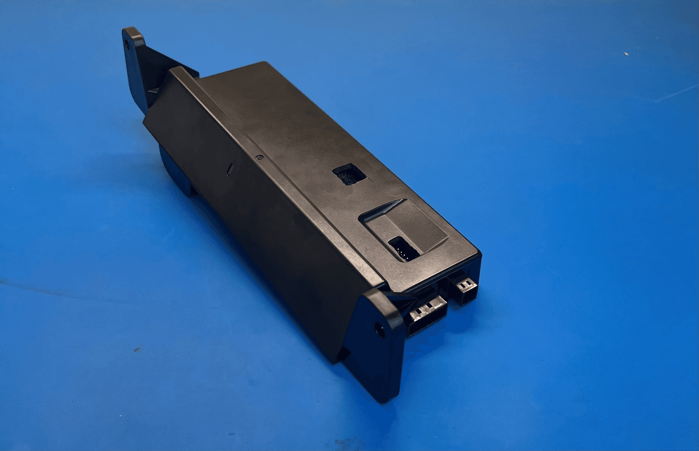
2ASJR-LYNXFLEET-52L
Feb 07, 2023ML3 Asset Tracker
Equipment Class
DTS - Digital Transmission System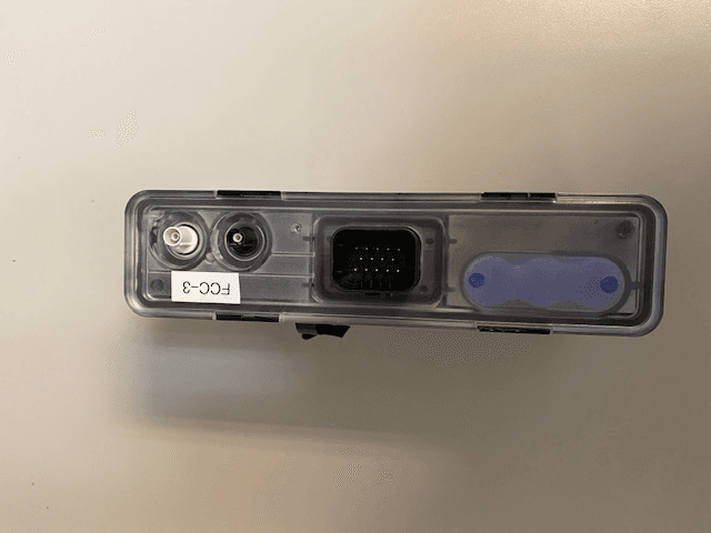
2ASJR-CM275-1113120
Nov 06, 2022GEN 2.75 Asset Tracker
Equipment Class
DTS - Digital Transmission System