2ASJR-LYNXFLEET-52LML3 Asset Tracker
Globetracker, ApS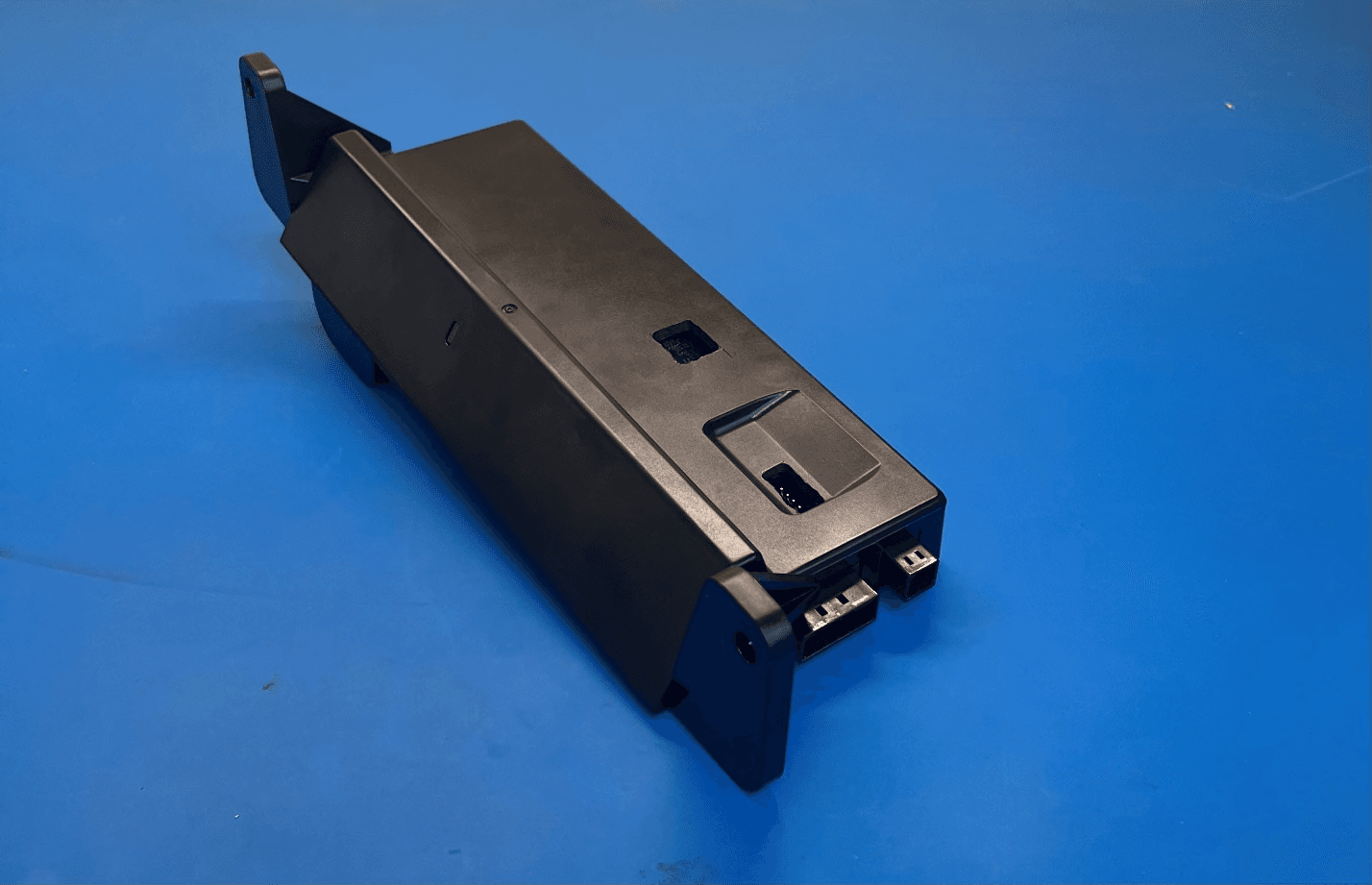
Click to zoom
Application Details
- Equipment Class
- DTS - Digital Transmission System
- Date of Grant
- Feb 07, 2023
- Application Purpose
- Original Equipment
- Date of Application
- Feb 07, 2023
- Equipment Note
- ML3 Asset Tracker
- Frequency Range
- 907.00000000 - 923.00000000
- Company
- Globetracker, ApS
- Country
- Denmark
Documents & Files
Document Text
Text extracted from the exhibit documents filed with the FCC. Open a document above to read the original.
Users Manual
ML3 Asset Tracker Instructions for Installing the Telematics Module For use with a ML3 controller only Tools Required: 1) Phillips/Flat screwdriver 2) Wire tie cutter 3) Silicone Caulk 4) Surface Cleaner (Isopropyl Alcohol) This instruction should be read through completely before proceeding. WARNING Power the unit on and update the ML3 controller software to the currently released ML3 software (TBD+) for the PrimeLINE models. Set the controller date and time in GMT. You may refer to the operations and service manual for detailed explanation. Before proceeding with installation, set ON/OFF switch and circuit breaker to OFF position. Disconnect power plug from the unit. Follow local lockout tagout procedures for working on the equipment. Parts required per assembly: ITEM PART NUMBER PART NAME QTY 1 12-00930-00 TELEMATICS MODULE AND HARNESS 1 2 58-01441-01 STA-STRAP 1 3 02-00311-02 LUBRICANT 1 4 66-U---1—3882 WIRE TIE 12 5 62-12305-00 LABEL 1 6 62-11270-32 LABEL,WARNING 1 7 62-11114-00 TAG 1 8 98-02739-00 INSTALL INSTRUCTIONS 1 Installation Procedure: 1. Ensure The ML3’s software is updated to TBD+ prior to install. 2. Record the information shown in Table 1. If installed in the field, please report the following data to [email protected]. Lynxfleet Device Serial Number Unit S/N Prefix Unit S/N Container Prefix Container No. Comm. Date (mm/dd/yyy) Controller S/N Software Version Install Location Customer 3. Open the control box door. See Figure 1. Figure 1: Control Box with Door Open 4. Remove the rain shield by removing the screws using a flat head screwdriver. Temporarily reinstall the two screws to hold display in place for the next step. See Figure 2a and 2b. 5. Clean area of any residue caulk on either the rain shield or the control box door. 6. Remove the two lower screws on the display. 7. Position the Telematics module with the flat side of the module facing towards the door and reinstall the two screws on the display to secure / mount the module in place. See Figure 3. Figure 2a: Removal of Rain Shield CIRCUIT BREAKER (CB-1) RAIN SHEILD ML3 CONTROLLER Figure 2b: Screws reinstalled Table 1: LynxFleet Device Warranty Information 8. Note the ground screw location and wire orientation. See Figure 4a. The module may need to be pushed up when tightening it down to clear the ground screw. 9. Apply electrical contact dielectric grease to the micro-USB connector on the ML3 and the micro-USB plug. See figure 5b. 10. Plug the micro-USB (item 1) to the ML3 controller connector and secure with the STA- Strap (item 3) to the USB guard and pull tie wrap to secure USB cable. See Figure 5c and 5d. 11. Locate the existing software tag and remove it from the unit. See figure 5d. 12. Take the clear plastic tag (item 7) and apply new label (item 6). See figure 5d. 13. Secure tag to the USB cable near the controller using wire tie. See figure 5d. 14. The power cable splits into QC and TRX2. Connect the wire marked QC to the QC connector on ML3 controller. See Figure 5e. Figure 3: Module Installation Figure 4a: Module Installation Figure 4b: Module Installed under rain shield 15. Loosen the mounting screws of the filter in front of the transformer using a flathead screwdriver so it can be rotated out of the way. See fig. 6a and 6b. Transformer See Figure 6c for installation of TRX2 wire Figure 5d: Add new warning tag and label (item 7 and 6) here on the USB harness. Remove existing warning tag. Figure 5e: QC connection Figure 5a: Harness Connections USB Guard Figure 5c: STA-STRAP (item 2) Secure to USB guard Figure 5b: Lubricant (item 3) to be applied to Micro-USB connection 16. Connect the wire marked TRX2 to the low voltage side of transformer at an open X2 connector. See Figure 6c. 17. Move the filter back to its original place and secure it with the mounting screw. 18. With the door fully open, neatly secure the wire harness using the wire ties and securing to existing display cable conduit. See Figure 7a. Step 12 Figure 6a: Filter location Figure 6b: Filter mounting screw Figure 6c: TRX2 connection to Transformer Mounting Screws to be loosened 19. Remove the top screws on the display. Reinstall rain shield using these screws. 20. Caulk along the top of the rain shield to prevent water ingression. See figure 7b. 21. Secure the wire harnesses to the rain shield via the hole as shown below in figure 7c. If there is no hole, drill a hole with a ¼” or 6mm drill bit. 22. Clean the rain shield with an appropriate cleaner and add the USB label (item 5) to the rain shield to the right of the harness mounting hole. Location shown in figure 7c. Figure 7a: Securing wire harness Figure 7b: Caulking of Rain Shield 23. Power on the reefer unit. 24. Check the operation of the Telematics Module using the LED display. The LED on the module will display accordingly. NOTE: Ensure there is good cellular coverage for a successful telematics device connection. Standard Startup Startup Gateway Connection Check Telemetry Ready/Sending On power LED no LED GAGG ----... G-G- G--- ----... Battery LED no LED AGAA ----... A-A- A--- ----... Time < 30 seconds < 30 seconds With Good Cell signal Warning/Error patterns LED patern Error/Warning description Recommended Action R-R- R-R- R--- ----... SIM Detection ERROR IoT device replacement R-R- R-R- ----... SIM CELL Network Reg ERROR IoT device replacement** R-R- R-R- ----... SIM DATA Network Reg ERROR IoT device replacement** R-R- R--- ----... SIM APN ERROR IoT device replacement** R-R- ----... Controller serial number incorrect on ML3 ML3 replacement** AAAA ---- ... GGGG ---- ... Connection to internet but not to Lynx Fleet Ok; no action required. Figure 7c: Routing wire harness and label location KEY A= Amber G= Green R= Red A/G/R -> LED ON ~250MS - -> LED OFF ~250MS ... -> Pattern repeats Commented [NMJ1]: Missing instruction to power up unit. No LED for more 2 minutes Communication between ML3 controller and Telematics device defective. Step 1: Check Power Su…
Text truncated - open the document above for the full version.
Attestation Statements
(Insert Company Letterhead) Letter of Authorization and Anti- Drug Statement Applicant Name:Globe Tracker ApS Address: Strandgade 91, 4th Floor DK-1401 Copenhagen K Denmark Product Name: ML5 Asset Tracker Model Number: LYNXFLEET-52L FCC ID:2ASJR-LYNXFLEET-52L We authorize: CETECOM Inc., to act on our behalf on all matters concerning the above named equipment. We declare that CETECOM Inc. is allowed to forward all information related to the approval project to the Federal Communications Commission and discuss any issues concerning the approval application. The applicant must certify that neither the applicant nor any party to the application is subject to a denial of Federal benefits, that include FCC benefits, pursuant to Section 5301 of the Anti-Drug Abuse Act of 1988, 21 U.S.C. § 862 because of a conviction for possession or distribution of a controlled substance. See 47 CFR 1.2002(b) for the definition of a "party" for these purposes. Does the applicant or authorized agent so certify? ☒ Yes I certify that I am authorized to sign this application. All of the statements herein and the exhibits attached hereto, are true and correct to the best of my knowledge and belief. In accepting a Grant of Equipment Authorization as a result of the representations made in this application, the applicant is responsible for (1) labeling the equipment with the exact FCC ID specified in this application, (2) compliance statement labeling pursuant to the applicable rules, and (3) compliance of the equipment with the applicable technical rules. If the applicant is not the actual manufacturer of the equipment, appropriate arrangements have been made with the manufacturer to ensure that production units of this equipment will continue to comply with the FCC's technical requirements. Authorizing an agent to sign this application, is done solely at the applicant's discretion; however, the applicant remains responsible for all statements in this application. If an agent has signed this application on behalf of the applicant, a written letter of authorization which includes information to enable the agent to respond to the above section 5301 (Anti-Drug Abuse) Certification statement has been provided by the applicant. It is understood that the letter of authorization must be submitted to the FCC upon request, and that the FCC reserves the right to contact the applicant directly at any time. Signature of Authorized Person Filing: Mark P Oudshoorn Title: Director of Engineering Date: 01/23/2023
Attestation Statements
Globe Tracker ApS. Mr Mark Oudshoorn Strandgade 91, 4th floor DK-1401 Copenhagen K Denmark Federal Communications Commission 7535 Oakland Mills Road Columbia, MD 21046 2/6/2023 Attestation Statement according to 2.911(d)(5)(i) and 2.911(d)(5)(ii) FCC ID: 2ASJR-LYNXFLEET-52L TO WHOM IT MAY CONCERN: Hereby we certify that the equipment for which authorization is sought is not “covered” equipment prohibited from receiving an equipment authorization pursuant to section 2.903 of the FCC rules. Further we certify that, as of the date of the filing of the application, Globe Tracker ApS. is not identified on the Covered List as an entity producing “covered” equipment. Sincerely, Mark P Oudshoorn Director of Engineering _______________ (signature & company stamp) Globe Tracker ApS Mark Oudshoorn 941-212-7960 [email protected]
Attestation Statements
Globe Tracker, ApS Strandgade 91, 4th floor DK-1401 Copenhagen K Denmark Federal Communication Commission 7435 Oakland Mills Road Columbia, MD 21046 2/6/2023 Attestation Statement according to 2.911(d)(7) FCC ID: 2ASJR-LYNXFLEET-52L TO WHOM IT MAY CONCERN: We, Globe Tracker America Inc. 1748 Independence Blvd Building A, Sarasota Florida 34234 confirms to maintain legal representation for no less than one year after the grantee has terminated all marketing and importation or the conclusion of any Commission-related proceeding involving the equipment. _______________ (signature & company stamp) Globe Tracker ApS. Mark P Oudshoorn 941-212-7960 [email protected]
Cover Letter(s)
Federal Communications Commission Equipment Authorization Division 7435 Oakland Mills Road Columbia, MD 21048 Date: 01/23/2023 Subject: Request for Permanent Confidentiality FCC ID: 2ASJR-LYNXFLEET-52L To Whom It May Concern: In accordance with §0.457(d) and §0.459 of CFR 47, and KDB 726920, Globe Tracker ApS herebyrequests permanent confidentiality for documents filed under the following exhibit types: 1.Block Diagram 2.Schematic Diagram 3.Part List 4.Operational Description These items contain detailed system and equipment description and related information about the product which Globe Tracker ApS considers to be proprietary, confidential and a custom design which otherwise would not be released to the general public. Since this design is a basis from which future technological products will evolve, Globe Tracker ApS also feels that this information would be of benefit to its competitors, and that the disclosure of the information in these exhibits would give our competitors an unfair advantage in the market. We are aware that exhibit types cover letters, attestations, label document, test reports, RF exposure information (SAR and MPE reports), cannot be requested to be classified confidential and are thus subject to publication, as will be documents of all other exhibits types for which we have not requested a confidentiality classification. Best Regards, _______________________________ Signature Name: Mark Oudshoorn Title: Director of Engineering Company Name: Globe Tracker ApS Address: Strandgade 91, 4 th Floor DK-1401 Copenhagen K Denmark
Cover Letter(s)
Federal Communications Commission Equipment Authorization Division 7435 Oakland Mills Road Columbia, MD 21048 Date: 01/23/2023 Subject: Request for Short Term Confidentiality FCC-ID: 2ASJR-LYNXFLEET-52L To Whom It May Concern: In accordance with §0.457(d) and §0.459 of CFR 47, Globe Tracker ApS herebyrequests short term confidentiality for documents filed under the following exhibit types: 1.External Photographs 2.Internal Photographs 3.User / Instruction Manual 4.Test Set-up Photographs until the product will be publicly announced. Short term confidentiality release date / period: 180 days from grant issue date These items contain detailed system and equipment description and related information about the product which Globe Tracker ApS considers to be proprietary, confidential and a custom design which otherwise would not be released to the general public. Since this design is a basis from which future technological products will evolve, Globe Tracker ApS also feels that this information would be of benefit to its competitors, and that the disclosure of the information in these exhibits would give our competitors an unfair advantage in the market. We are informed and aware of our obligation that we have to inform the involved TCB in written and in due time if we intend to market the product prior to the above specified confidentiality release date so that the short term confidentiality classification can be reset prior to product launch. We are aware that exhibit types cover letters, attestations, label document, test reports, RF exposure information (SAR and MPE reports), cannot be requested to be classified confidential and are thus subject to publication, as will be documents of all other exhibits types for which we have not requested a confidentiality classification. Best Regards, ____________________________________ Signature Name: Mark Oudshoorn Title: Director of Engineering Company Name: Globe Tracker ApS Address: Strandgade 91, 4 th Floor DK-1401 Copenhagen K Denmark
External Photos
Views of assembly TOP BOT FRONT REAR LEFT SIDE RIGHT SIDE ISOMETRIC
ID Label/Location Info
LABEL LOCATION LABEL LOCATION D C B A A B C D 1 2 3 4 5 6 7 8 7 6 5 4 3 2 COPYRIGHT © 2022 GLOBE TRACKER, ApS ALL RIGHTS RESERVED 0: 1.0 mm 0.0 0.5 mm 0.00: 0.25 mm 0.000: 0.125 mm ANGULAR: 0.5 DEG UNITS OF MEASURE: FINISH: TITLE B SHEET 1 OF 1 TOLERANCES EXCEPT WHERE NOTED MATERIAL: REVPART NO. SIZE CONFIDENTIAL DRAWN: QA: APPROVED: MFG: CHECKED: GLOBE TRACKER, ApS CVR#33579004 DK-1401 Copenhagen K, DENMARK CONFIDENTIAL JJT METRIC, mm MA ES MA MO SCALE 1:1 D C B A A B C D 1 2 3 4 5 6 7 8 7 6 5 4 3 2 COPYRIGHT © 2022 GLOBE TRACKER, ApS ALL RIGHTS RESERVED 0: 1.0 mm 0.0 0.5 mm 0.00: 0.25 mm 0.000: 0.125 mm ANGULAR: 0.5 DEG UNITS OF MEASURE: FINISH: TITLE B 29NOV2022 N/A SHEET 1 OF 1 TOLERANCES EXCEPT WHERE NOTED MATERIAL: REVPART NO. SIZE CONFIDENTIAL DRAWN: QA: APPROVED: MFG: CHECKED: GLOBE TRACKER, ApS CVR#33579004 DK-1401 Copenhagen K, DENMARK CONFIDENTIAL JJT ML3 PRODUCT LABEL LOCATON REFERENCE DRAWING METRIC, mm N/A MA ES MA MO SCALE 1:1 A ASM-0029R Technical Data Sheet BRADY B-483A THERMAL TRANSFER PRINTABLE LABEL STOCK TDS No. B-483A Effective Date: 10/05/2022 Description: GENERAL Print Technology:Thermal transfer Material Type:White Polyester Finish:Glossy Adhesive:Permanent Rubber Based APPLICATIONS B-483A is designed for high adhesion to textured metals and low surface energy plastics. Print-On-Demand floor labels can be created using ToughStripe TM labels (B-483A colors overlaminatedwith B-634 clear polyester overlaminate). RECOMMENDED RIBBONS Brady Series R6000 Halogen Free Brady Series R4900 Brady Series R4400 colored thermal transfer ribbons. REGULATORY/AGENCY APPROVALS UL: B-483A is a UL Recognized Component to UL969 Labelingand Marking Standard when printed with the Brady Series R6000 Halogen Free and the Brady Series R4900 ribbons. See UL file MH17154 for specific details.UL information can be accessed on-line at UL.com in the UL Product iQ area. CSA: B-483A is a CSA Accepted material when printedwith the Brady Series R6000 Halogen Free ribbon. See CSA file 041833 for specific details. CSA information can be accessed online at https://www.csagroup.org/testing-certification/product-listing/ For information on the Weee-RoHS compliance status for a Brady Product go to one of the following websites: In Canada:www.bradycanada.ca/weee-rohs In Europe:www.bradyeurope.com/rohs In Japan:www.brady.co.jp/products/labelsuse/rohs All other regions:www.bradyid.com/weee-rohs SPECIAL FEATURES B-483A is specifically designed to adhere to powder coated surfaces. Details: PHYSICAL PROPERTIESTEST METHODSAVERAGE RESULTS ThicknessASTM D 1000 -Substrate -Adhesive -Total(excluding liner) 0.0020 inch (0.051 mm) 0.0020 inch (0.051 mm) 0.0040 inch (0.102 mm) Adhesion to: -Stainless Steel -Textured ABS -Polypropylene ASTM D 1000 20 minute dwell 24 hour dwell 20 minute dwell 24 hour dwell 20 minute dwell 24 hour dwell 155 oz/in (169 N/100 mm) 160 oz/in (174 N/100 mm) 55 oz/in (60 N/100 mm) 54 oz/in (59 N/100 mm) 140 oz/in (153 N/100 mm) 143 oz/in (156 N/100 mm) -Painted Enamel -Powder Coated Metal 20 minute dwell 24 hour dwell 20 minute dwell 24 hour dwell 144 oz/in (157 N/100 mm) 149 oz/in (162 N/100 mm) 102 oz/in (111 N/100 mm) 104 oz/in (113 N/100 mm) TackASTM D 2979 Polyken™ Probe Tack 0.5 second dwell 39 oz (1122 g) Performance properties tested on B-483A printed with the Brady Series R6000 Halogen Free and the Brady Series R4900 ribbons. Printed samples of B-483A were laminated to aluminum before exposure to the indicated environmental condition. Results the same for both ribbons unless noted otherwise. PERFORMANCE PROPERTIESTEST METHODSTYPICAL RESULTS Long Term High Service Temperature30 days at 248°F (120°C)No visible effect Long Term Low Service Temperature30 days at 40°F (-40°C)No visible effect Humidity Resistance30 days at 100°F (37°C), 95% R.H.No visible effect UV Light Resistance30 days in UV Sunlighter™ 100No visible effect WeatherabilityASTM G155, Cycle 1 30 days in Xenon Arc Weatherometer No visible effect Salt Fog ResistanceASTM B 117 30 days in 5% salt fog solution chamber No visible effect Abrasion ResistanceTaber Abraser, CS-10 grinding wheels, 250 g/arm (Fed. Std. 191A, Method 5306) R6000 Halogen Free: Print legible after 100 cycles PERFORMANCE PROPERTYCHEMICAL RESISTANCE Samples printed with the Brady Series R6000 Halogen Free and the Brady Series R4900 ribbons. Testing was conducted after 24 hour dwell. Testing consisted of 5 cycles of 10 minute immersions in the specified chemical reagent followed by 30 minute recovery periods. After final immersion, samples rubbed 10 times with cotton swab saturated with test fluid. CHEMICAL REAGENTSUBJECTIVE OBSERVATION OF VISUAL CHANGE EFFECT TO LABEL STOCK R4900R6000 Halogen Free Methyl Ethyl KetoneSlight adhesive oozeNo visible effect w/o rub, complete print removal after rub No visible effect w/o rub, complete print removal after rub TolueneNo visible effectNo visible effect w/o rub, complete print removal after rub No visible effect w/o rub, complete print removal after rub Isopropyl AlcoholNo visible effectNo visible effect with or without rub No visible effect with or without rub Mineral SpiritsSlight adhesive oozeNo visible effect with or without rub No visible effect with or without rub JP-8 Jet FuelNo visible effectNo visible effect with or without rub No visible effect with or without rub SAE 20 WT OilNo visible effectNo visible effect with or without rub No visible effect with or without rub Mil 5606 OilSlight adhesive oozeNo visible effect with or without rub No visible effect with or without rub Speedi Kut Cutting Oil 332No visible effectNo visible effect with or without rub Not Tested GasolineNo visible effectNo visible effect w/o rub, slight print removal after rub No visible effect Rust Veto® 342No visible effectNo visible effect with or without rub Not Tested Skydrol® 500B-4No visible effectModerate print removal w/o rub, complete print removal with rub No visible effect w/o rub, severe print removal after rub Super Agitene…
Text truncated - open the document above for the full version.
Internal Photos
GlobeTracker ML3 Photos Views of PCB PCB Top PCB Top – Shields removed PCB Bot
RF Exposure Info
Radio Frequency Exposure Evaluation Report FOR: Globe Tracker ApS Model: LYNXFLEET-52L Product Description: Asset Tracking Device / Data Modem FCC ID: 2ASJR-LYNXFLEET-52L IC: 25752-LYNXFLEET52 Per: CFR Part Part1 (1.1307 &1.1310), Part 2 (2.1091), FCC KDB 447498 D01 General RF Exposure Guidance v06 ISEDC RSS-102 Issue 5 Report number: EMC_GLOBE_006_22001_FCC_ISED_MPE_Rev1 DATE: 2023-01-23 CETECOM Inc. 411 Dixon Landing Road Milpitas, CA 95035 U.S.A. Phone: + 1 (408) 586 6200 Fax: + 1 (408) 586 6299 E-mail: [email protected] http://www.cetecom.com CETECOM Inc. is a Delaware Corporation with Corporation number: 2905571 V5.0 2015-10-27 © Copyright by CETECOM Test Report #: EMC_GLOBE_006_22001_FCC_ISED_MPE_Rev1 FCC ID: 2ASJR-LYNXFLEET-52L Date of Report 2023-01-23 Page 2 of 7 IC: 25752-LYNXFLEET52 Page 2 of 7 1 Assessment This RF Exposure evaluation report provides evidence for compliance of the below identified device with the RF Exposure limits for mobile devices as defined in FCC CFR Part 1 (1.1307 &1.1310), Part 2 (2.1091) and IC standard RSS-102 issue 5 under worst case conditions (measured or rated RF output power, antenna gain, distance towards human body, multiple transmitter information as presented by the applicant). In addition, maximum antenna gain or minimum distance towards the human body is calculated respectively, where relevant. The device meets the limits as stipulated by the above given FCC and IC rule parts based on available specifications for worst case conditions at 20cm distance to the body. Company Description Model # Globe Tracker ApS Asset Tracking Device / Data Modem LYNXFLEET-52L Report reviewed by: TCB Evaluator 2023-01-23 Compliance Arndt Stoecker (Director of Regulatory Services) Date Section Name Signature Responsible for the Report: 2023-01-23 Compliance Cheng Song (EMC Engineer) Date Section Name Signature Test Report #: EMC_GLOBE_006_22001_FCC_ISED_MPE_Rev1 FCC ID: 2ASJR-LYNXFLEET-52L Date of Report 2023-01-23 Page 3 of 7 IC: 25752-LYNXFLEET52 Page 3 of 7 2 Administrative Data 2.1 Identification of the Testing Laboratory Issuing the Test Report Company Name: CETECOM Inc. Department: Compliance Street Address: 411 Dixon Landing Road City/Zip Code Milpitas, CA 95035 Country USA Telephone: +1 (408) 586 6200 Fax: +1 (408) 586 6299 Lab Manager: Arndt Stoecker Responsible Project Leader: Akanksha Baskaran 2.2 Identification of the Client / Manufacturer Client’s Name: Globe Tracker ApS Street Address: Strandgade 91, 4th floor City/Zip Code DK-1401 Copenhagen K Country USA Identification of the Manufacturer Manufacturer’s Name: Same as Client Manufacturers Address: City/Zip Code Country Test Report #: EMC_GLOBE_006_22001_FCC_ISED_MPE_Rev1 FCC ID: 2ASJR-LYNXFLEET-52L Date of Report 2023-01-23 Page 4 of 7 IC: 25752-LYNXFLEET52 Page 4 of 7 3 Equipment under Assessment Model No: LYNXFLEET-52L HW Version : Rev2 SW Version : 20.00.01 FCC-ID : 2ASJR-LYNXFLEET-52L IC: 25752-LYNXFLEET52 PMN: ML3 Asset Tracker Product Description: Asset Tracking Device / Data Modem Radio Information: LoRa: Module: Semtech SX1262 Frequency of Operation: 433 MHz, 863-870 MHz (EU), 902-928 MHz (NA) Antenna Information as declared: 900 ISM Peak Gain: -8.9 dBi Power Supply/ Rated Operating Voltage Range: AC Input: Voltage Range: 12-36 VAC, Frequency: 50/60 Hz DC Input: Voltage Range: 9-18 VDC Lithium Ion Battery Operating Temperature Range -25 ºC to 70 ºC Sample Revision Prototype Unit; Production Unit; Pre-Production Test Report #: EMC_GLOBE_006_22001_FCC_ISED_MPE_Rev1 FCC ID: 2ASJR-LYNXFLEET-52L Date of Report 2023-01-23 Page 5 of 7 IC: 25752-LYNXFLEET52 Page 5 of 7 4 RF Exposure Limits and FCC and IC Basic Rules For the specific described radio apparatus the following basic limits and rules apply for both, FCC and IC where not indicated differently. 4.1 Power Density Limits acc. to FCC 1.1310(e) / RSS-102 i5, cl. 4: FCC Frequency Range (MHz) Power density (mW/cm 2 ) Averaging time (minutes) 300 – 1500 f (MHz) /1500 30 1500 – 100000 1.0 30 IC Frequency Range (MHz) Power density (W/m 2 ) Averaging time (minutes) 300 – 6000 0.02619 x f (MHz) 0.6834 6 4.2 Routine Environmental Evaluation Categorical Exclusion Limits acc. to FCC 2.1091(c) / RSS-102, cl. 2.5 (rounded to 1 decimal point): FCC operating frequency < 1.5GHz: excluded if ERP < 1.5W / 31.8dBm (EIRP: 33.9 dBm); operating frequency > 1.5GHz: excluded if ERP < 3.0W / 34.8dBm (EIRP: 36.9 dBm); IC 300MHz < = operating frequency < 6 GHz: excluded if EIRP < 0.0131 x f (MHz) 0.6834 W 4.3 RF Exposure Estimation (MPE Estimation) Having available the source based average output power and peak antenna gain or the ERP/EIRP of the specified device and for a known minimum distance of its radiating structures from the body of persons according to its use cases (at least 20cm) the power density at that distance can be estimated by the following formula for plane-wave equivalent conditions (far-field conditions), when ground reflection is neglected. 2 4R PG S where: S = power density (mW/cm 2 or W/m 2 ) P = power input to the antenna (mW or W) G = power gain of the antenna in the direction of interest relative to an isotropic radiator R = distance to the center of radiation of the antenna (cm or m) Test Report #: EMC_GLOBE_006_22001_FCC_ISED_MPE_Rev1 FCC ID: 2ASJR-LYNXFLEET-52L Date of Report 2023-01-23 Page 6 of 7 IC: 25752-LYNXFLEET52 Page 6 of 7 5 Evaluations 5.1 Analysis of RF Exposure FCC: LoRa Operating frequency < 1.5GHz, ERP20cm Limit = 2040 x 0.907 = 1850.28mW = 1.85W Actual ERP = 0.0003W < 1.85W; Excluded. IC: LoRa EIRP Limit = 0.0131 x f (MHz) 0.6834 = 1.38W Actual EIRP = 0.0004W < 1.38W; Excluded. 5.2 Conclusion: LoRa radio complies with routine environmental evaluation requirements for RF exposure. Simultaneous transmission with other radios is not applicable in LYNXFLEET-52L. Test Report #: EMC_GLOBE_006_22001_FCC_ISED_MPE_Rev1 FCC ID: 2ASJR-LYNXFLEET-52L Date of Report 2023-01-23 Page 7 of 7 IC: 25752-LYNXFLEET52 Pa…
Text truncated - open the document above for the full version.
Test Report
A2LA Accredited IC recognized # 3462B-1 CETECOM Inc. 411 Dixon Landing Road Milpitas, CA 95035 U.S.A. Phone: + 1 (408) 586 6200 Fax: + 1 (408) 586 6299 E-mail: [email protected] http://www.cetecom.com CETECOM Inc. is a Delaware Corporation with Corporation number: 2905571 © Copyright by CETECOM FCC / ISED Test Report For: Globe Tracker ApS Model: LYNXFLEET-52L Product Description: Asset Tracking Device / Data Modem FCC ID: 2ASJR-LYNXFLEET-52L IC: 25752-LYNXFLEET52 Applied Rules and Standards: 47 CFR Part 15.247 (DTS) RSS-247 Issue 2 (DTSs) & RSS-Gen Issue 5 REPORT #: EMC_GLOBE_006_22001_FCC_15_247_Rev1 DATE: 2023-01-23 Test Report #: EMC_GLOBE_006_22001_FCC_15_247_Rev1 FCC ID: 2ASJR-LYNXFLEET-52L Date of Report 2023-01-23 Page 2 of 38 IC: 25752-LYNXFLEET52 TABLE OF CONTENTS 1 ASSESSMENT .............................................................................................................................................................. 3 2 ADMINISTRATIVE DATA ............................................................................................................................................... 4 2.1 IDENTIFICATION OF THE TESTING LABORATORY ISSUING THE EMC TEST REPORT ........................................................................... 4 2.2 IDENTIFICATION OF THE CLIENT ............................................................................................................................................. 4 2.3 IDENTIFICATION OF THE MANUFACTURER ................................................................................................................................. 4 3 EQUIPMENT UNDER TEST (EUT) ................................................................................................................................... 5 3.1 EUT SPECIFICATIONS ......................................................................................................................................................... 5 3.2 EUT SAMPLE DETAILS ......................................................................................................................................................... 6 3.3 ACCESSORY EQUIPMENT (AE) DETAILS ................................................................................................................................... 6 3.4 TEST SAMPLE CONFIGURATION ............................................................................................................................................. 6 3.5 JUSTIFICATION FOR WORST CASE MODE OF OPERATION ............................................................................................................ 6 4 SUBJECT OF INVESTIGATION ...................................................................................................................................... 7 5 MEASUREMENT RESULTS SUMMARY .......................................................................................................................... 7 6 MEASUREMENT UNCERTAINTY.................................................................................................................................... 8 6.1 ENVIRONMENTAL CONDITIONS DURING TESTING: ...................................................................................................................... 8 6.2 DATES OF TESTING: ............................................................................................................................................................ 8 7 MEASUREMENT PROCEDURES .................................................................................................................................... 9 7.1 RADIATED MEASUREMENT .................................................................................................................................................... 9 7.2 POWER LINE CONDUCTED MEASUREMENT PROCEDURE .......................................................................................................... 11 7.3 RF CONDUCTED MEASUREMENT PROCEDURE ....................................................................................................................... 11 8 TEST RESULT DATA .....................................................................…
Text truncated - open the document above for the full version.
Contact Information
Applicant
Mark Oudshoorn(Engineer)
Test Firm
CETECOM Inc.Meinolf Glunz
[email protected]408-586-6301
Technical Specifications
| # | Rule Parts | Frequency Range | Power Output |
|---|---|---|---|
| 1 | 15C | 907 MHz - 923 MHz | 3.30 mW |
Other Applications from Globetracker, ApS
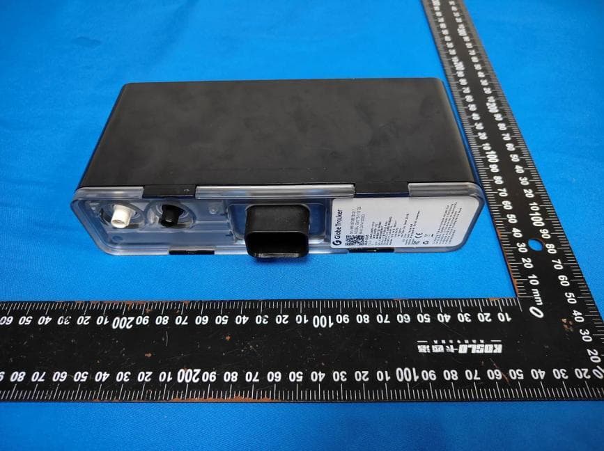
2ASJR-CM275-1113130
Dec 17, 2025Asset Tracking Device / Data Modem
Equipment Class
DTS - Digital Transmission System2ASJR-CM25-1113120
Nov 08, 2022Wireless Tracking Cargo System
Equipment Class
DTS - Digital Transmission System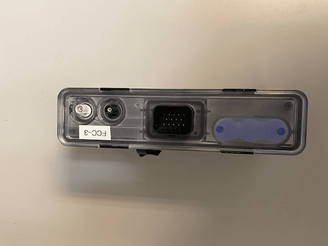
2ASJR-CM275-1113120
Nov 06, 2022GEN 2.75 Asset Tracker
Equipment Class
DTS - Digital Transmission System