2ASO2PANDARQTV2Rangefinder
Hesai Technology Co., Ltd.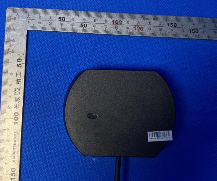
Click to zoom
Application Details
- Equipment Class
- JAD - Part 15 Class A Digital Device
- Date of Grant
- Mar 24, 2020
- Application Purpose
- Original Equipment
- Date of Application
- Mar 23, 2020
- Equipment Note
- Rangefinder
- Company
- Hesai Technology Co., Ltd.
- Country
- China
Documents & Files
Document Text
Text extracted from the exhibit documents filed with the FCC. Open a document above to read the original.
Users Manual
HESAI WeChat www.hesaitech.com Q01-en-2001A1 PandarQT 64-Channel Short-Range Mechanical LiDAR User Manual Contents Safety Notice ................................................................................................................. 1 1 Introduction ............................................................................................................ 1 1.1 Operating Principle .................................................................................................... 1 1.2 LiDAR Structure ........................................................................................................... 2 1.3 Channel Distribution .................................................................................................. 3 1.4 Specifications ............................................................................................................... 4 2 Setup ......................................................................................................................... 5 2.1 Mechanical Installation ............................................................................................. 5 2.2 Interfaces ....................................................................................................................... 7 2.3 Connection Box (Optional) ...................................................................................... 9 2.4 Get Ready to Use ...................................................................................................... 12 3 Data Structure ...................................................................................................... 13 3.1 Point Cloud Data Packet ........................................................................................ 14 3.2 GPS Data Packet ....................................................................................................... 19 4 Web Control ......................................................................................................... 25 4.1 Home ............................................................................................................................ 26 4.2 Settings ........................................................................................................................ 27 4.3 Azimuth FOV .............................................................................................................. 30 4.4 Operation Statistics .................................................................................................. 33 4.5 Upgrade .......................................................................................................................34 5 PandarView ........................................................................................................... 35 5.1 Installation ...................................................................................................................35 5.2 Use .................................................................................................................................36 5.3 Features ........................................................................................................................38 6 Communication Protocol .................................................................................. 42 6.1 Packet Structure ........................................................................................................42 6.2 Frequently Used Commands ................................................................................43 7 Sensor Maintenance ........................................................................................... 51 8 Troubleshooting .................................................................................................. 52 Appendix I Absolute Time and Laser Firing Time .......................................... 54 I.1 Absolute Time of Point Cloud Data Packets.....................................................54 I.2 Laser Firing Time ........................................................................................................54 Appendix II PTP Protocol...................................................................................... 58 Appendix III Certification Info ............................................................................. 60 Appendix IV Support and Contact ..................................................................... 61 1 Safety Notice PLEASE READ AND FOLLOW ALL INSTRUCTIONS CAREFULLY AND CONSULT ALL RELEVANT NATIONAL AND INTERNATIONAL SAFETY REGULATIONS FOR YOUR APPLICATION. ◼ Caution To avoid violating the warranty and to minimize the chances of getting electrically shocked, please do not disassemble the device. The device must not be tampered with and must not be changed in any way. There are no user-serviceable parts inside the device. For repairs and maintenance inquiries, please contact an authorized Hesai Technology service provider. ◼ Laser Safety Notice – Laser Class 1 This device satisfies the requirements of ▪ IEC 60825-1:2014 ▪ 21 CFR 1040.10 and 1040.11 except for deviations (IEC 60825-1 Ed.3) pursuant to Laser Notice No.56, dated May 8, 2019 NEVER LOOK INTO THE TRANSMITTING LASER THROUGH A MAGNIFYING DEVICE (MICROSCOPE, EYE LOUPE, MAGNIFYING GLASS, ETC.) 2 ◼ Safety Precautions In all circumstances, if you suspect that the device malfunctions or is damaged, stop using it immediately to avoid potential hazards and injuries. Contact an authorized Hesai Technology service provider for more information on device disposal. Handling This device contains metal, glass, plastic, as well as sensitive electronic components. Improper handling such as dropping, burning, piercing, and squeezing may cause damage to the device. Enclosure This device contains high-speed rotating parts. To avoid potential injuries, DO NOT operate the device if the enclosure is loose or damaged. Repair DO NOT open and repair the device without direct g…
Text truncated - open the document above for the full version.
Test Report
FCC Test Report Product Name : Rangefinder Model No. : PandarQT Applicant : Hesai Technology Co., Ltd. Address : No.2 Building, No.468 Xinlai Road, Jiading District, Shanghai, China Date of Receipt : Dec.22, 2021 Test Date : N/A Issued Date : Dec.29, 2021 Report No. : 21C0757R-IT-US-P01V01 Report Template No. : TRF_FCC Part 15 Subpart 15B_EMC_V1.2 The test results presented in this report relate only to the object tested. This report is not used for social proof in China (or Mainland China) market The measurement result is considered in conformance with the requirement if it is within the prescribed limit, It is not necessary to calculate the uncertainty associated with the measurement result. This report must not be used to claim product endorsement by TAF or any agency of the government. This report shall not be reproduced, except in full, without the written approval of DEKRA Testing and Certification (Suzhou) Co., Ltd. Report No.: 21C0757R-IT-US-P01V01 Page: 2 of 26 Product Name : Rangefinder Applicant : Hesai Technology Co., Ltd. Address : No.2 Building, No.468 Xinlai Road, Jiading District, Shanghai, China Manufacturer : Hesai Technology Co., Ltd. Address : No.2 Building, No.468 Xinlai Road, Jiading District, Shanghai, China Model No. : PandarQT Brand Name : HESAI EUT Voltage : AC 100-240V, 50/60Hz Test Voltage : AC 120V,60Hz Applicable Standard : FCC CFR Title 47 Part 15 Subpart B: 2020 ICES 003 Issue 7 2020 ANSI C63.4: 2014 Test Result : Complied Performed Location : DEKRA Testing and Certification (Suzhou) Co., Ltd. No.99 Hongye Rd., Suzhou Industrial Park, Suzhou,215006, Jiangsu, China TEL: +86-512-62515088 / FAX: +86-512-62515098 Tested By : (Project Engineer: Marlon Mei) Approved By : (Manager: Oscar Shi) Issued Date : Dec.29, 2021 Report No. : 21C0757R-IT-US-P01V01 Report No.: 21C0757R-IT-US-P01V01 Page: 3 of 26 TABLE OF CONTENTS Description Page 1. General Information ..................................................................................................... 5 1.1. EUT Description .............................................................................................. 5 1.2. Mode of Operation ........................................................................................... 5 1.3. Tested System Details ..................................................................................... 6 1.4. Configuration of Tested System ....................................................................... 7 1.5. EUT Exercise Software ................................................................................... 8 2. Technical Test .............................................................................................................. 9 2.1. Summary of Test Result .................................................................................. 9 2.2. List of Test Equipment ................................................................................... 10 2.3. Test Environment ........................................................................................... 11 2.4. Measurement Uncertainty ............................................................................. 12 3. Conducted disturbance .............................................................................................. 13 3.1. Test Specification ........................................................................................... 13 3.2. Test Setup ..................................................................................................... 13 3.3. Limit ............................................................................................................... 14 3.4. Test Procedure .............................................................................................. 14 3.5. Deviation from Test Standard ........................................................................ 14 3.6. Test Result ..................................................................................................... 15 4. Radiated disturbance ................................................................................................. 17 4.1. Test Specification ........................................................................................... 17 4.2. Test Setup ..................................................................................................... 17 4.3. Limit ............................................................................................................... 18 4.4. Test Procedure .............................................................................................. 19 4.5. Deviation from Test Standard ........................................................................ 21 4.6. Test Result ..................................................................................................... 22 5. Attachment ................................................................................................................ 26 Report No.: 21C0757R-IT-US-P01V01 Page: 4 of 26 Document History Report NO. Date Description 21C0757R-IT-US-P01V01 Dec.29, 2021 First release Report No.: 21C0757R-IT-US-P01V01 Page: 5 of 26 1. General Information 1.1. EUT Description Product Name Rangefinder Model No. PandarQT Brand Name HESAI Note 1: The EUT information is from customer declaration. Note 2: The GPS hardware in this report is an accessory equipment that does not belong to the EUT in order to simulate the maximum load output for this test. Manufacturer actually ship products to clients without GPS hardware. Note 3: This report was based on report No. 2032074E-IT-US-P01V03, the change as below: 1. Updated the name and address of the applicant. 2. Updated the name and address of the manufacturer. 3. Updated the standard version. 4. According to the customer's requirements, Delete the test photos and EUT photos in the original report. Test photos and EUT photos are shown in the report No. 2032074E-IT-US-P01V03. By the technology evalu…
Text truncated - open the document above for the full version.
Test Setup Photos
Test Photograph Test Mode: Mode 1 Description: Front View of Radiated disturbance Test Setup (Below 1GHz) Test Mode: Mode 1 Description: Rear View of Radiated disturbance Test Setup (Below 1GHz) Test Mode: Mode 1 Description: Front View of Radiated disturbance Test Setup (Above 1GHz) Test Mode: Mode 1 Description: Rear View of Radiated disturbance Test Setup (Above 1GHz) Test Photograph Test Mode: Mode 1 Description: Front View of Conducted disturbance Test Setup Test Mode: Mode 1 Description: Side View of Conducted disturbance Test Setup
Contact Information
Applicant
Li Jinyu(Certification Manager)
Technical Contact
DEKRA Testing and Certification (Suzhou) Co., Ltd.Janet Xu
[email protected]86-0512-6251-5088
No.99 Hongye RD.Suzhou Industrial Park, Loufeng Hi · Suzhou · China
Non-Technical Contact
DEKRA Testing and Certification (Suzhou) Co., Ltd.
[email protected]86-0512-6251-5088
Test Firm
DEKRA Testing and Certification (Suzhou) Co., Ltd.Janet Xu
[email protected]86 512 6251 50885113
Technical Specifications
| # | Rule Parts | Frequency Range | Power Output |
|---|---|---|---|
| 1 | 15B | - | - |
Other Applications from Hesai Technology Co., Ltd.
2ASO2CBPANDARQT
Jan 27, 2021Connection Box
Equipment Class
JAD - Part 15 Class A Digital Device
2ASO2CBPANDARXT
Jan 27, 2021Connection Box
Equipment Class
JAD - Part 15 Class A Digital Device
2ASO2PANDARXT
Jul 22, 2020Rangefinder
Equipment Class
JAB - Part 15 Class B Digital Device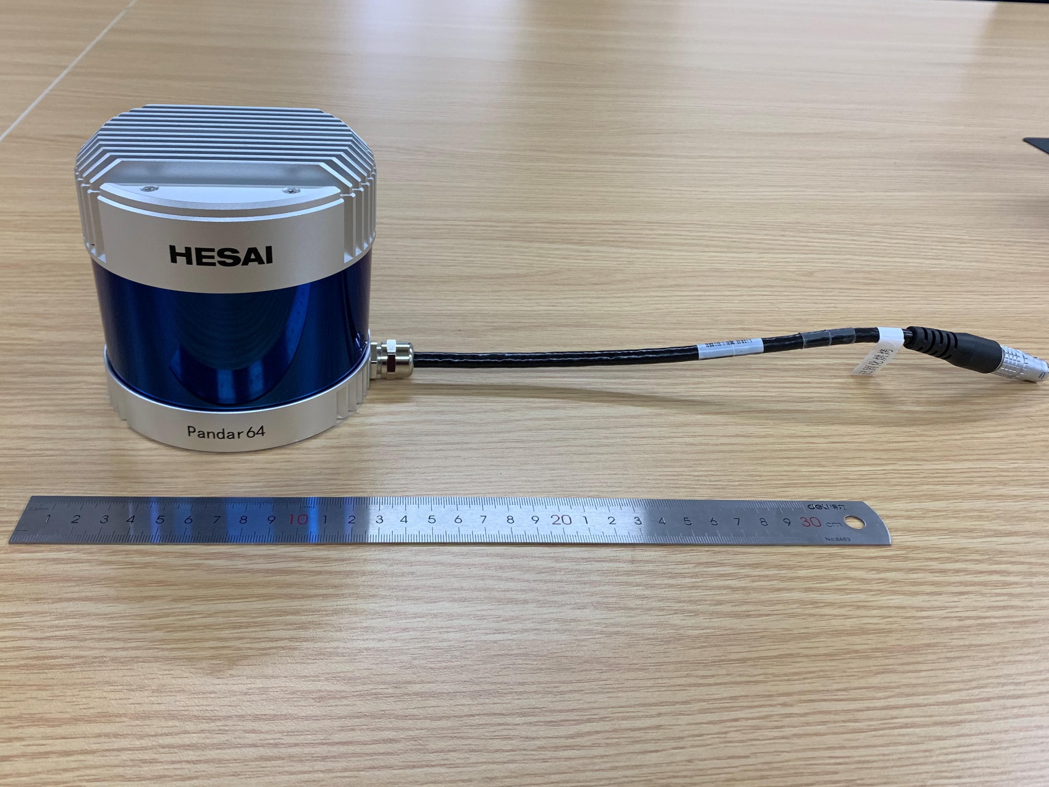
2ASO2PANDAR64
May 12, 2020Rangefinder
Equipment Class
JAD - Part 15 Class A Digital Device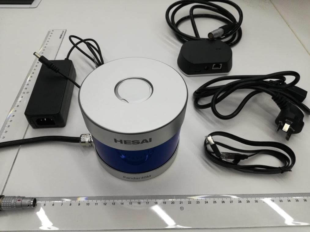
2ASO2PANDAR40M
Apr 21, 2020Rangefinder
Equipment Class
JAD - Part 15 Class A Digital Device