2AU5D-LXX12Wireless Charging Pad
Legrand/Pass & Seymour
Click to zoom
Application Details
- Equipment Class
- DCD - Part 15 Low Power Transmitter Below 1705 kHz
- Date of Grant
- Aug 09, 2021
- Application Purpose
- Original Equipment
- Date of Application
- Aug 09, 2021
- Equipment Note
- Wireless Charging Pad
- Frequency Range
- 0.12770000 - 0.12770000
- Company
- Legrand/Pass & Seymour
- Country
- United States
Documents & Files
Document Text
Text extracted from the exhibit documents filed with the FCC. Open a document above to read the original.
Users Manual
WIREMOLD ® Wireless Charging Pad – 15W Chargeur sans fil – 15 W Base de carga inalámbrica – 15 W No: 1027015_RA – 0721 Installation Instructions • Notice d’Installation• Instrucciones de Instalación Country of Origin • Pays d'origine • País de origen: Made in China • Fabriqué aux China • Hecho en China IMPORTANT: Please read all instructions before beginning installation Legrand electrical systems conform to and should be properly grounded in compliance with requirements of the current National Electrical Code or codes administered by local authorities. All electrical products may present a possible shock or fire hazard if improperly installed or used. Legrand electrical products may bear the mark of a Nationally Recognized Testing Laboratory and should be installed in conformance with current local and/or the National Electrical Code. IMPORTANT : Veuillez lire l'ensemble des instructions avant de commencer l'installation. Les systèmes électriques Legrand sont conformes au Code National de l'électricité (National Electrical Code) ou aux codes locaux en vigueur et doivent être mis à la terre conformément à ces codes. Tous les produits électriques peuvent présenter un risque d'électrocution ou d'incendie s'ils ne sont pas installés ou utilisés correctement. Les produits électriques Legrand peuvent porter la marque d'un laboratoire reconnu et doivent être installés conformément au Code national de l'électricité et/ou aux codes locaux en vigueur. IMPORTANTE: Lea todas las instrucciones antes de comenzar la instalación. Los sistemas eléctricos Legrand cumplen con los requisitos del Código Eléctrico Nacional (National Electrical Code, NEC) actual o con los códigos impuestos por las autoridades locales y deben conectarse a tierra consecuentemente. Todos los productos eléctricos pueden presentar un riesgo de descarga o incendio si se los instala o utiliza incorrectamente. Los productos eléctricos Legrand pueden llevar la marca de un laboratorio de pruebas reconocido a nivel nacional y se deben instalar conforme al código local en vigencia o al Código Eléctrico Nacional. Catalog Number(s) • Numéro(s) de Catalogue • Número(s) de Catálogo: WCP15 RJ 45 x 2 x 2 US LED 2,5 m 98.4in RJ 45 0 776 38L 0776 41L/42L/43L WCP15 WPC QI - EN 62311 - ICNIRP FCC ID: 2AU5D-LXX12 IC: 25764-LXX12 HVIN: 077641L/077642L/077643L 119-140 kHz - 42dBμA/m max. The socket outlet should be installed near the equipment and shall be easily accessible. Make sure the power supply is disconnected before any intervention. Strictly comply with instructions for installation and use. The undersigned, LEGRAND, declares that radio equipment of the type (0 776 40L/41L/42L/43L /45L/46L/47L/48L/49L) complies with Directive 2014/53/EU. The full text of the EU declaration of conformity can be found at: www.legrandoc.com La prise doit être installée à proximité de l’équipement et être facilement accessible. Avant toute intervention, couper le courant. Respecter strictement les conditions d’installation et d’utilisation. Le soussigné, LEGRAND, déclare que l’équipement radioélectrique du type (0 776 40L/ 41L/42L/43L/45L/46L/47L/48L/49L) est conforme à la directive 2014/53/UE. Le texte complet de la déclaration UE de conformité est disponible à l’adresse suivante : www.legrandoc.com La toma se debe instalar cerca del equipo y ser fácilmente accesible. Antes de cualquier intervención, cortar la corriente.Respetar estrictamente las condiciones de instalación y de utilización. El abajo firmante, LEGRAND, declara que el equipo radioeléctrico de tipo (0 776 40L/41L/ 42L/43L/45L/46L/47L/48L/49L) cumple con la directiva 2014/53/UE. El informe completo de la declaración UE de conformidad se encuentra disponible en: www.legrandoc.com 2 Warning: Changes or modifications to this unit not expressly approved by the party responsible for compliance could void the user's authority to operate the equipment. NOTE: This equipment has been tested and found to comply with the limits for a Class B digital device, pursuant to Part 15 of the FCC Rules. These limits are designed to provide reasonable protection against harmful interference in a residential installation. This equipment generates, uses, and can radiate radio frequency energy and, if not installed and used in accordance with the instructions, may cause harmful interference to radio communications. However, there is no guarantee that interference will not occur in a particular installation. If this equipment does cause harmful interference to radio or television reception, which can be determined by turning the equipment off and on, the user is encouraged to try to correct the interference by one or more of the following measures: – Reorient or relocate the receiving antenna. – Increase the separation between the equipment and receiver. – Connect the equipment into an outlet on a circuit different from that to which the receiver is connected. – Consult the dealer or an experienced radio TV technician for help. Avertissement : Tous changements ou modifications apportés à cet appareil, qui ne sont pas expressément appouvés par la partie responsable de la conformité, sont susceptibles d‘annuler l‘autorisation d‘utilisation de cet équipement. REMARQUE : Cet équipement a été testé et déclaré conforme aux limites imposées aux appareils numériques de classe B, conformément à la partie 15 des règles FCC. Ces limites sont destinées à assurer une protection raisonnable contre les interférences nuisibles dans une installation résidentielle. Cet équipement génère, utilise et peut émettre de l‘énergie radioélectrique et, s‘il n‘est pas installé et utilisé conformément aux instructions, risque de causer des interférences nuisibles aux communications radio. Toutefois, il n‘y a aucune garantie que des interférences ne se produiront pas dans une installation particulière. Si cet équipement provoque des interférences nuisibles à la réception radio ou télévision, ce qui peut être déterminé en mettant l‘équipement hors et so…
Text truncated - open the document above for the full version.
External Photos
INTERTEK TESTING SERVICE FCC ID: 2AU5D-LXX12 IC: 25764-LXX12 Configuration Photographs Worst-Case Radiated Emissions (Front View) INTERTEK TESTING SERVICE FCC ID: 2AU5D-LXX12 IC: 25764-LXX12 Configuration Photographs Worst-Case Radiated Emissions (Back View) INTERTEK TESTING SERVICE FCC ID: 2AU5D-LXX12 IC: 25764-LXX12 Configuration Photographs Worst-Case Radiated Emissions (Front View)
Internal Photos
INTERTEK TESTING SERVICE FCC ID: 2AU5D-LXX12 IC: 25764-LXX12 Equipment Photographs (Internal) INTERTEK TESTING SERVICE FCC ID: 2AU5D-LXX12 IC: 25764-LXX12 Equipment Photographs (Internal) INTERTEK TESTING SERVICE FCC ID: 2AU5D-LXX12 IC: 25764-LXX12 Equipment Photographs (Internal) INTERTEK TESTING SERVICE FCC ID: 2AU5D-LXX12 IC: 25764-LXX12 Equipment Photographs (Internal) INTERTEK TESTING SERVICE FCC ID: 2AU5D-LXX12 IC: 25764-LXX12 Equipment Photographs (Internal)
RF Exposure Info
2/F., Garment Centre, 576 Castle Peak Road, Kowloon, Hong Kong SAR, China. Telephone: (852) 2173 8888 Facsimile: (852) 2785 5487 www.intertek.com Page 1 of 7 1. GENERAL INFORMATION 1.1 CLIENT INFORMATION Applicant: Legrand/Pass & Seymour FCC ID: 2AU5D-LXX12 1.2 EUT INFORMATION Product Name: Wireless Charger Model No.: TBA Trade Mark: N/A DUT Stage: Production Unit Operating Frequency Range: 127.7KHz Antenna Type: Coil Antenna Power Supply AC/DC Adaptor (Input: 110 – 240V / Output: 48VDC) Sample Received Date: May 8, 2020 Sample Tested Date: May 12, 2020 to May 18, 2020 1.3 OTHER INFORMATION Support Equipment Client device – 15W Specific Loader (Provided by Intertek) Model: YBZ 1.4 GENERAL DESCRIPTION OF APPLIED STANDARDS The EUT is a RF product, according to the specifications of the manufacturers. It must comply with the requirements of the following standards: According to KDB680106 D01 RF Exposure Wireless Charging Apps v03r1 (January 27, 2021), the requirement of RF exposure for the Wireless Charging device shall be met. 2/F., Garment Centre, 576 Castle Peak Road, Kowloon, Hong Kong SAR, China. Telephone: (852) 2173 8888 Facsimile: (852) 2785 5487 www.intertek.com Page 2 of 7 2. EQUIPMENT LIST Test Equipment List Equipment No. Equipment Manufacturer Model No. Serial Number Cal. date (mm dd, yyyy) Cal. Due date (mm dd, yyyy) EW-3412 Electric and Magnetic Field Probe - Analyzer NARDASAFETY EHP-200A 170WX91004 Jan 23, 2021 Jan 23, 2022 3. MPE EVALUATION 3.1 REFERENCE DOCUMENTS FOR EVALUATION According to KDB680106 D01 RF Exposure Wireless Charging Apps v03r1 (January 27, 2021), the requirement of RF exposure for the Wireless Charging device shall be met. 3.2 MPE COMPLIANCE REQUIREMENT 3.2.1 Limits 3.2.1.1 According to §1.1307(b)(1), system operating under the provisions of this section shall be operating in a manner that the public is not exposed to radio frequency energy level in excess limit for maximum permissible exposure. Limits for Occupational / Controlled Exposure Frequency range (MHz) Electric Field Strength (E) (V/m) Magnetic Field Strength (H) (A/m) Power Density (S) (mW/cm 2 ) Averaging Times | E | 2 , | H | 2 or S (minutes) 0.3-3.0 614 1.63 (100)* 6 3.0-30 1842/f 4.89/f (900/f)* 6 30-300 61.4 0.163 1.0 6 300-1500 / / F/300 6 1500-100000 / / 5 6 Limits for General Population/Uncontrolled Exposure Frequency range (MHz) Electric Field Strength (E) (V/m) Magnetic Field Strength (H) (A/m) Power Density (S) (mW/cm 2 ) Averaging Times | E | 2 , | H | 2 or S (minutes) 0.3-1.34 614 1.63 *100 30 1.34-30 824/f 2.19/f *180/f 2 30 30-300 27.5 0.073 0.2 30 300-1,500 / / f/1500 30 1,500-100,000 / / 1.0 30 Note: f = frequency in MHz: * = Plane-wave equivalents power density. 2/F., Garment Centre, 576 Castle Peak Road, Kowloon, Hong Kong SAR, China. Telephone: (852) 2173 8888 Facsimile: (852) 2785 5487 www.intertek.com Page 3 of 7 3.2.2 Test Procedure Enabled the EUT to transmit and receive data continue a. The field strength of both E-field and H-field was measured at 15 cm surrounding the device and 20 cm above the top surface using the equipment list above for determining compliance with the MPE requirements of FCC Part 1.1310. b. For 15W wireless charging, specific loading is required for providing Max. output power for testing. c. Maximum E-field and H-field measurements were made 15cm from each side of the EUT. Along the side of the EUT and still 15cm away from the edge of the EUT, the field probes were positioned at the location where there is maximum field strength. The maximum E-field and H-field is reported below. d. This device uses a wireless charging circuit for power transfer operating at the frequency of 120-127.7 kHz. Thus, the 300 kHz limits were used: E-field Limit = 614 (V/m); H-field limit = 1.63 (A/m). 3.2.3 Test setup 2/F., Garment Centre, 576 Castle Peak Road, Kowloon, Hong Kong SAR, China. Telephone: (852) 2173 8888 Facsimile: (852) 2785 5487 www.intertek.com Page 4 of 7 Note - The RF exposure test is performed in the shield room - The test distance is between the edge of the charger and the geometric center of probe - The aggregate at 15 cm surrounding the device and 20 cm above the top surface from transmitting coil is demonstrated. - Test Position: Rear, Right, Front, Left, Top, Bottom 2/F., Garment Centre, 576 Castle Peak Road, Kowloon, Hong Kong SAR, China. Telephone: (852) 2173 8888 Facsimile: (852) 2785 5487 www.intertek.com Page 5 of 7 3.3 TEST DATA Charging with specific receiver loading (15W) – Max. output power E-Field Strength H-Field Strength Remark: The device meets the KDB680106 D01 RF Exposure Wireless Charging Apps v03r1 (January 27, 2021), the requirement of RF exposure for the Wireless Charging device. Transmitting coil is demonstrated to be less than 50% of the MPE limit. Test Mode Probe Position (V/m) C-Rear Probe Position (V/m) B-Right Probe Position (V/m) D-Front Probe Position (V/m) A-Left Probe Position (V/m) E-Top Probe Position (V/m) F-Bottom Limits (V/m) Max. 15W power wireless charging 1.7206 2.0479 2.3230 2.1637 2.2950 0.8755 614/2 = 307 Test Mode Probe Position (A/m) C-Rear Probe Position (A/m) B-Right Probe Position (A/m) D-Front Probe Position (A/m) A-Left Probe Position (A/m) E-Top Probe Position (A/m) F- Bottom Limits (A/m) Max. 15W power wireless charging 0.0896 0.2036 0.3311 0.1246 0.2292 0.0773 1.63/2 = 0.815 2/F., Garment Centre, 576 Castle Peak Road, Kowloon, Hong Kong SAR, China. Telephone: (852) 2173 8888 Facsimile: (852) 2785 5487 www.intertek.com Page 6 of 7 Test Setup Photo: Worst case 2/F., Garment Centre, 576 Castle Peak Road, Kowloon, Hong Kong SAR, China. Telephone: (852) 2173 8888 Facsimile: (852) 2785 5487 www.intertek.com Page 7 of 7 *** End of Report ***
Test Report
2/F., Garment Centre, 576 Castle Peak Road, Kowloon, Hong Kong SAR, China. Telephone: (852) 2173 8888 Facsimile: (852) 2785 5487 www.intertek.com Intertek’s standard Terms and Conditions can be obtained at our website http://www.intertek.com/terms/. The test report only allows to be revised within the retention period unless further standard or the requirement was noticed. This report is for the exclusive use of Intertek's Client and is provided pursuant to the agreement between Intertek and its Client. Intertek's responsibility and liability are limited to the terms and conditions of the agreement. Intertek assumes no liability to any party, other than to the Client in accordance with the agreement, for any loss, expense or damage occasioned by the use of this report. Only the Client is authorized to permit copying or distribution of this report and then only in its entirety. Any use of the Intertek name or one of its marks for the sale or advertisement of the tested material, product or service must first be approved in writing by Intertek. The observations and test results in this report are relevant only to the sample tested. This report by itself does not imply that the material, product, or service is or has ever been under an Intertek certification program. © 2017 Intertek Page 1 of 20 TEST REPORT Report No.: 21041174HKG-001 Legrand/Pass & Seymour Application For Certification (Original Grant) FCC ID: 2AU5D-LXX12 Transceiver Prepared and Checked by: Approved by: Signed On File Lee For Yiu, Florey Assistant Engineer Wong Kwok Yeung, Kenneth Senior Lead Engineer Date: June 17, 2021 TEST REPORT Legrand/Pass & Seymour Intertek Report No: 21041174HKG-001 Page 2 of 20 GENERAL INFORMATION Grantee: Legrand/Pass & Seymour Grantee Address: 50 Boyd Ave, Syracuse, New York 13209, United States Contact Person: Kris Glassford Tel: 315-468-8014 Fax: N/A e-mail: [email protected] Brand Name: Legrand Model: 077641L Additional Model: 077642L, 077643L Type of EUT: Transceiver Description of EUT: Wireless Charging Pad Serial Number: N/A FCC ID: 2AU5D-LXX12 Date of Sample Submitted: April 21, 2021 Date of Test: April 21, 2021 to May 14, 2021 Report No.: 21041174HKG-001 Report Date: June 17, 2021 Environmental Conditions: Temperature: +10 to 40°C Humidity: 10 to 90% Conclusion: Test was conducted by client submitted sample. The submitted sample as received complied with the 47 CFR Part 15 Certification. TEST REPORT Legrand/Pass & Seymour Intertek Report No: 21041174HKG-001 Page 3 of 20 SUMMARY OF TEST RESULT Test Specification Reference Results Radiated Emission Radiated Emission on the Bandedge 15.209 Pass Transmitter Power Line Conducted Emissions 15.207 Pass The equipment under test is found to be complying with the following standards: FCC Part 15, October 1, 2019 Edition Note: 1. The EUT uses a permanently attached antenna which, in accordance to section 15.203, is considered sufficient to comply with the pervisions of this section. 2. Pursuant to FCC part 15 Section 15.215(c), the 20 dB bandwidth of the emission was contained within the frequency band designated (mentioned as above) which the EUT operated. The effects, if any, from frequency sweeping, frequency hopping, other modulation techniques and frequency stability over excepted variations in temperature and supply voltage were considered. TEST REPORT Legrand/Pass & Seymour Intertek Report No: 21041174HKG-001 Page 4 of 20 TABLE OF CONTENTS 1.0 GENERAL DESCRIPTION ................................................................................................ 5 1.1 Product Description ................................................................................................... 5 1.2 Related Submittal(s) Grants ....................................................................................... 5 1.3 Test Methodology ...................................................................................................... 5 1.4 Test Facility ................................................................................................................ 5 2.0 SYSTEM TEST CONFIGURATION ..................................................................................... 6 2.1 Justification ................................................................................................................ 6 2.2 EUT Exercising Software ............................................................................................. 6 2.3 Special Accessories .................................................................................................... 6 2.4 Measurement Uncertainty ......................................................................................... 6 2.5 Support Equipment List and Description .................................................................... 6 3.0 EMISSION RESULTS ....................................................................................................... 7 3.1 Field Strength Calculation .......................................................................................... 7 3.2 Radiated Emission Configuration Photograph ............................................................ 8 3.3 Radiated Emission Data ............................................................................................. 8 3.4 Conducted Emission Configuration Photograph ........................................................ 8 3.5 Conducted Emission Data .......................................................................................... 8 4.0 EQUIPMENT PHOTOGRAPHS ...................................................................................... 12 5.0 PRODUCT LABELLING .................................................................................................. 12 6.0 TECHNICAL SPECIFICATIONS ....................................................................................... 12 7.0 INSTRUCTION MANUAL .................................................................................…
Text truncated - open the document above for the full version.
Contact Information
Applicant
Kris Glassford(Testing Lab & Certification Manager)
Technical Contact
Intertek Testing Services Hong Kong Ltd.Kenneth Wong
[email protected](852) 3912 6902
2/F., Garment Centre, · Hong Kong
Non-Technical Contact
Intertek Testing Services Hong Kong Ltd.Kenneth Wong
[email protected](852) 3912 6902
Test Firm
Intertek Testing Services Hong Kong Ltd.Billy Chow
Technical Specifications
| # | Rule Parts | Frequency Range | Power Output |
|---|---|---|---|
| 1 | 15C | 0.1277 MHz - 0.1277 MHz | - |
Other Applications from Legrand/Pass & Seymour
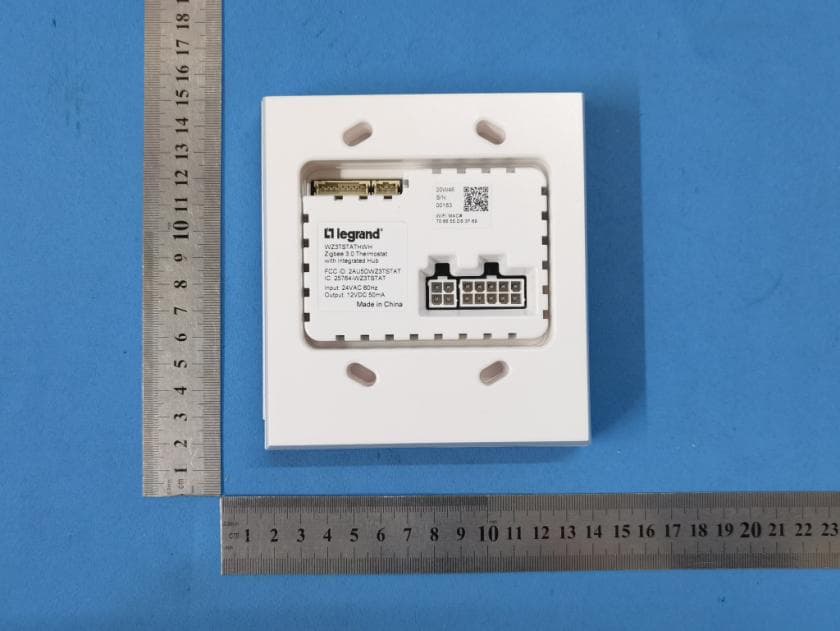
2AU5DWZ3TSTAT
Jun 28, 2021Thermostat
Equipment Class
DTS - Digital Transmission System
2AU5D-WNRH1
Mar 11, 2021Smart Gateway with Netatmo
Equipment Class
DTS - Digital Transmission System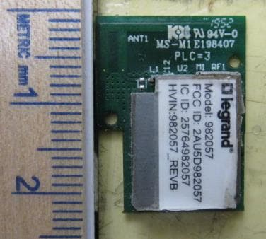
2AU5D982057
Jun 07, 2020982057 Module
Equipment Class
DTS - Digital Transmission System