2AU5DWZ3TSTATThermostat
Legrand/Pass & Seymour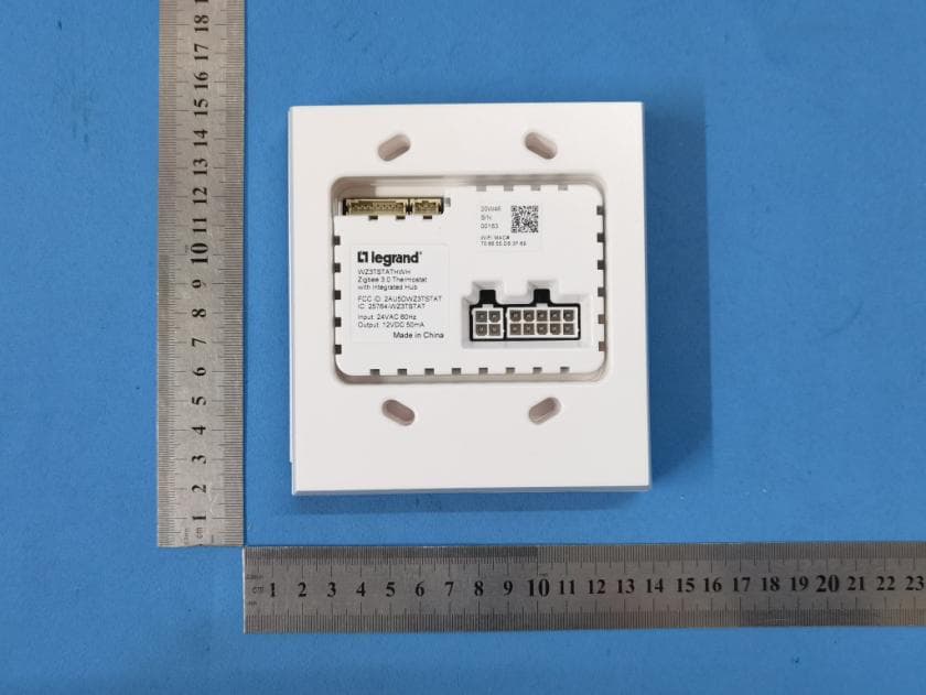
Click to zoom
Application Details
- Equipment Class
- DTS - Digital Transmission System
- Date of Grant
- Jun 28, 2021
- Application Purpose
- Original Equipment
- Date of Application
- Jun 28, 2021
- Equipment Note
- Thermostat
- Frequency Range
- 2412.00000000 - 2462.00000000
- Company
- Legrand/Pass & Seymour
- Country
- United States
Documents & Files
Document Text
Text extracted from the exhibit documents filed with the FCC. Open a document above to read the original.
Users Manual
No: 341319 6/21 Catalog Number(s): WZ3TSTATH Pass & Seymour ® WZ3TSTATH Thermostat Installation Manual Installation Instructions Country of Origin: Made in China For the latest version of this document please visit: https://www.legrand.us/wiring-devices/smart-lighting/smart-hospitality/smart-thermostat-with-zigbee-3.0-hub/p/wz3tstathbk READ & SAVE THESE INSTRUCTIONS! WARNING: To reduce the risk of fire, electric shock, or product damage, do not expose this apparatus to rain, moisture, immersion, dripping or splashing. No objects filled with liquids, such as vases, should be placed on this apparatus. CAUTION: • Do not obstruct the unit’s ventilation openings with curtains, fabrics, and similar items. • Do not place sources of open flames such as candles on the unit. • Do not place in areas of direct heating or cooling vents • 5.2 GHz band is restricted to indoor use only. Purpose of Control: Operating Control TYPE 1 or TYPE 2 Action: TYPE 1.C External Pollution Situation: Pollution Degree 2 Rated Impulse Voltage: 330V REGULATORY INFORMATION FCC NOTICE: This device complies with Part 15 of the FCC rules. Operation is subject lo the following two conditions; (1) this device nay not cause harmful interference, and (2) this device must accept any interference received, including interference that may cause undesirable operation. This equipment has been tested and found lo comply with the limits for a Class B digital device, pursuant to Part 15 of the FCC Rules. These limits are designed to provide reasonable protection against harmful interference in a residential installation. This equipment generates, uses, and can radiate radio frequency energy and, if not installed and used in accordance with the instruction, may cause harmful interference to radio communications. However, there is no guarantee that interference will not occur in a particular installation. If this equipment does cause harmful interference lo radio or television reception, which can be determined by turning the equipment off and on, the user is encouraged to try to correct the interference by one or more of the following measures: • Reorient or relocate the receiving antenna • Increase the separation between the equipment and receiver • Connect the equipment into an outlet on a circuit different from that to which the receiver is connected • Consult the dealer or an experienced radio/TV technician for help NOTE: Any changes or modifications to this device that are not expressly approved by the manufacturer will void the warranty and the user’s authority to operate the equipment. FCC ID: 2AU5DWZ3TSTAT The distance between user and device should be no less than 20cm. IC Notice: This device contains licence-exempt transmitter(s)/ receiver(s) that comply with Innovation, Science and Economic Development Canada’s licence-exempt RSS(s). Operation is subject to the following two conditions: (1) This device may not cause interference. (2) This device must accept any interference, including interference that may cause undesired operation of the device. IC: 25764-WZ3TSTAT HVIN: WZ3TSTATH IMPORTANT SAFETY INSTRUCTIONS Read these operating instructions carefully before using the unit. Follow the safety instructions on the unit and the applicable safety instructions listed below. Keep these instructions for future reference. 1. Read these instructions. 2. Keep these instructions. 3. Heed all warnings. 4. Follow the instructions. 5. Do not use this apparatus in or near water. 6. Clean only with a dry cloth. 7. Do not block any ventilation openings. Install in accordance with the manufacturer’s instructions. 8. Do not install near any heat sources such as radiators, heat registers, stoves, or other apparatus (including amplifiers) that produce heat. 9. Use only attachments/accessories specified by the manufacturer. 10. Refer all servicing to qualified service personnel. Servicing is required when the apparatus has been damaged in any way, such as power plug damage, liquid spills or objects falling onto the apparatus. Also, if the apparatus has been exposed to rain or moisture, does not operate normally, or has been dropped. THERMOSTAT OVERVIEW 1. System overview The WZ3TSTATH is an integrated smart thermostat and room gateway that enables new user experiences for today’s smart hotel rooms. It is intended to be installed by trained installers and requires integration into an Enseo hospitality system. 1.1. Indicators Temperature – Indicates the current room temperature. Display can be in Fahrenheit or Celsius. The temperature decimal is used in Celsius mode System Off – Indicates that the HVAC system is off Auto – Indicates that the HVAC is in auto mode. Note: Auto and Off are exclusive of each other Set Temperature – Indicates set point temperature for thermostat Room Temperature – Indicates current room temperature Fan Speed – Indicates fan speed. Indicators are speeds 1-3 and Auto. ItemDescriptionDefault Power / Modes 1. When system powerup, it will first enter sleep mode. 2. Proximity triggers the system into wakeup mode. 3. Press to power on the HVAC system into Auto mode. Off F/C 1. Press once, select the C, Celsius mode. 2. Press again, toggle to F, Fahrenheit mode. 3. When user change to C or F, the corresponding room temperature and set point temperature needs to be updated 4. The F/C button only active at wakeup mode F Fan 1. Fan speed. Press to toggle between Auto->1->2->3 if HVAC system is at auto mode. Auto Increase Press increase shall increase the set point temperature of Auto Mode. Each step is 1 degree in F or 0.5 degree in C mode) When the user touches the temperature increase button, the display will switch to the current set point temperature. It can be modified using the increase/decrease buttons. After 3 seconds of inactivity the system will set the last set point temperature. 68F or 20C Decrease Press decrease shall decrease the set point temperature of Auto Mode. Each step is 1 degree in F or 0.5 degree in C mode) W…
Text truncated - open the document above for the full version.
Users Manual
No: 341319 6/21 Catalog Number(s): WZ3TSTATH Pass & Seymour ® WZ3TSTATH Thermostat Installation Manual Installation Instructions Country of Origin: Made in China For the latest version of this document please visit: https://www.legrand.us/wiring-devices/smart-lighting/smart-hospitality/smart-thermostat-with-zigbee-3.0-hub/p/wz3tstathbk READ & SAVE THESE INSTRUCTIONS! WARNING: To reduce the risk of fire, electric shock, or product damage, do not expose this apparatus to rain, moisture, immersion, dripping or splashing. No objects filled with liquids, such as vases, should be placed on this apparatus. CAUTION: • Do not obstruct the unit’s ventilation openings with curtains, fabrics, and similar items. • Do not place sources of open flames such as candles on the unit. • Do not place in areas of direct heating or cooling vents • 5.2 GHz band is restricted to indoor use only. Purpose of Control: Operating Control TYPE 1 or TYPE 2 Action: TYPE 1.C External Pollution Situation: Pollution Degree 2 Rated Impulse Voltage: 330V REGULATORY INFORMATION FCC NOTICE: This device complies with Part 15 of the FCC rules. Operation is subject lo the following two conditions; (1) this device nay not cause harmful interference, and (2) this device must accept any interference received, including interference that may cause undesirable operation. This equipment has been tested and found lo comply with the limits for a Class B digital device, pursuant to Part 15 of the FCC Rules. These limits are designed to provide reasonable protection against harmful interference in a residential installation. This equipment generates, uses, and can radiate radio frequency energy and, if not installed and used in accordance with the instruction, may cause harmful interference to radio communications. However, there is no guarantee that interference will not occur in a particular installation. If this equipment does cause harmful interference lo radio or television reception, which can be determined by turning the equipment off and on, the user is encouraged to try to correct the interference by one or more of the following measures: • Reorient or relocate the receiving antenna • Increase the separation between the equipment and receiver • Connect the equipment into an outlet on a circuit different from that to which the receiver is connected • Consult the dealer or an experienced radio/TV technician for help NOTE: Any changes or modifications to this device that are not expressly approved by the manufacturer will void the warranty and the user’s authority to operate the equipment. FCC ID: 2AU5DWZ3TSTAT The distance between user and device should be no less than 20cm. IC Notice: This device contains licence-exempt transmitter(s)/ receiver(s) that comply with Innovation, Science and Economic Development Canada’s licence-exempt RSS(s). Operation is subject to the following two conditions: (1) This device may not cause interference. (2) This device must accept any interference, including interference that may cause undesired operation of the device. IC: 25764-WZ3TSTAT HVIN: WZ3TSTATH IMPORTANT SAFETY INSTRUCTIONS Read these operating instructions carefully before using the unit. Follow the safety instructions on the unit and the applicable safety instructions listed below. Keep these instructions for future reference. 1. Read these instructions. 2. Keep these instructions. 3. Heed all warnings. 4. Follow the instructions. 5. Do not use this apparatus in or near water. 6. Clean only with a dry cloth. 7. Do not block any ventilation openings. Install in accordance with the manufacturer’s instructions. 8. Do not install near any heat sources such as radiators, heat registers, stoves, or other apparatus (including amplifiers) that produce heat. 9. Use only attachments/accessories specified by the manufacturer. 10. Refer all servicing to qualified service personnel. Servicing is required when the apparatus has been damaged in any way, such as power plug damage, liquid spills or objects falling onto the apparatus. Also, if the apparatus has been exposed to rain or moisture, does not operate normally, or has been dropped. 1. System overview The WZ3TSTATH is an integrated smart thermostat and room gateway that enables new user experiences for today’s smart hotel rooms. It is intended to be installed by trained installers and requires integration into an Enseo hospitality system. 1.1. Indicators Temperature – Indicates the current room temperature. Display can be in Fahrenheit or Celsius. The temperature decimal is used in Celsius mode System Off – Indicates that the HVAC system is off Auto – Indicates that the HVAC is in auto mode. Note: Auto and Off are exclusive of each other Set Temperature – Indicates set point temperature for thermostat Room Temperature – Indicates current room temperature Fan Speed – Indicates fan speed. Indicators are speeds 1-3 and Auto. ItemDescriptionDefault Power / Modes 1. When system powerup, it will first enter sleep mode. 2. Proximity triggers the system into wakeup mode. 3. Press to power on the HVAC system into Auto mode. Off F/C 1. Press once, select the C, Celsius mode. 2. Press again, toggle to F, Fahrenheit mode. 3. When user change to C or F, the corresponding room temperature and set point temperature needs to be updated 4. The F/C button only active at wakeup mode F Fan 1. Fan speed. Press to toggle between Auto->1->2->3 if HVAC system is at auto mode. Auto Increase Press increase shall increase the set point temperature of Auto Mode. Each step is 1 degree in F or 0.5 degree in C mode) When the user touches the temperature increase button, the display will switch to the current set point temperature. It can be modified using the increase/decrease buttons. After 3 seconds of inactivity the system will set the last set point temperature. 68F or 20C Decrease Press decrease shall decrease the set point temperature of Auto Mode. Each step is 1 degree in F or 0.5 degree in C mode) When the user touches…
Text truncated - open the document above for the full version.
Cover Letter(s)
Legrand/Pass & Seymour Agent Authorization Company: Legrand/Pass & Seymour Address: 50 Boyd Ave, Syracuse, New York 13029, United States Product Name: Thermostat Model Number(s): WZ3TSTATH Product Description: Thermostat We authorize MiCOM Labs Inc., 575 Boulder Court, Pleasanton, California 94566, USA, to act on our behalf on all matters concerning the certification of above named equipment. We declare that MiCOM Labs Inc. is allowed to forward all information related to the approval and certification of equipment to the regulatory agencies as required and to discuss any issues concerning the approval application. Any and all acts carried out by MiCOM Labs on our behalf shall have the same effect as acts of our own. Signature: Date: 2020-08-06 Name: Kris Glassford Title: Testing Lab & Certification Manager Company: Legrand/Pass & Seymour
Cover Letter(s)
< Legrand/Pass & Seymour > Office of Engineering Technology Federal Communications Commission 7435 Oakland Mills Road Columbia, MD21046 Date: 2020-08-06 Subject; Request for Long Term Confidentiality FCC ID: 2AU5DWZ3TSTAT To Whom It May Concern, Pursuant to the provisions of the Commission’s rules Title 47 Sections §0.457 and §0.459, we are requesting the Commission to withhold the following attachment(s) as confidential documents from public disclosure indefinitely. These documents contain detailed system and equipment descriptions and are considered as proprietary information in operation of the equipment. The public disclosure of these documents might be harmful to our company and would give competitors an unfair advantage in the market. Schematic Diagram Block Diagram Operational Description FCC Software Security Requirements for UNII devices It is our understanding that all measurement test reports, FCC ID label format and correspondence during the certification review process cannot be granted as confidential documents and this information will be available for public review once the grant of equipment authorization is issued. Sincerely, Signature: Name: Kris Glassford Title: Testing Lab & Certification Manager
External Photos
Test Model No.: WZ3TSATH
ID Label/Location Info
NOTES: Material: JH-500Y(50#PET+UL Color: White background with black printing Glue: Adhesive permanently Size: 30.5 x 30.5mm Material: JH-500Y(50#PET+UL Color: White background with black printing Glue: ahesive permanently Size: 20x15mm WWDY S/N: 00001 WIFI MAC# XX:XX:XX:XX:XX:XX WWDY S/N: 00001 WIFI MAC# XX:XX:XX:XX:XX:XX LEGT011/2 FCC ID: 2AU5DWZ3TSTAT IC: 25764-WZ3TSTAT Made in China WZ3TSTATH E258958 T40 Thermostat with Integrated Hub Operating temperature: 41-104°F Use Copper Conductor Only Use 16AWG wires rated at least 167°F For Use in Class 2 Circuit Only DC Output: 12V 50mA AC Terminal Output: 3A General Purpose or 1A Pilot duty AC Damper Output: 3A General Purpose Indoor use only Temp. Ind. and Reg. Equip. FCC ID: 2AU5DWZ3TSTAT IC: 25764-WZ3TSTAT Made in China WZ3TSTATH E258958 T40 Thermostat with Integrated Hub Operating temperature: 41-104°F Use Copper Conductor Only Use 16AWG wires rated at least 167°F For Use in Class 2 Circuit Only DC Output: 12V 50mA AC Terminal Output: 3A General Purpose or 1A Pilot duty AC Damper Output: 3A General Purpose Indoor use only Temp. Ind. and Reg. Equip.
Internal Photos
Test Model No.: WZ3TSATH
RF Exposure Info
FCC ID: 2AU5DWZ3TSTAT IC: 25764-WZ3TSTAT RF Exposure Evaluation FCC Limits The criteria listed in the following table shall be used to evaluate the environment impact of human exposure to radio frequency (RF) radiation as specified in 1.1307(b) Limits for Maximum Permissible Exposure (MPE) Frequency range (MHz) Electric field strength (V/m) Magnetic field strength (A/m) Power density (mW/cm 2 ) Averaging time (minutes) (A) Limits for Occupational/Controlled Exposures 0.3–3.0 614 1.63 *(100) 6 3.0–30 1842/f 4.89/f *(900/f 2 ) 6 30–300 61.4 0.163 1.0 6 300–1500 f/300 6 1500–100,000 5 6 (B) Limits for General Population/Uncontrolled Exposure 0.3–1.34 614 1.63 *(100) 30 1.34–30 824/f 2.19/f *(180/f 2 ) 30 30–300 27.5 0.073 0.2 30 300–1500 f/1500 30 1500–100,000 1.0 30 f = frequency in MHz Friis transmission formula: Pd = (Pout*G)/(4*pi*r 2 ) Where Pd = power density in mW/cm 2 , Pout = output power to antenna in mW; G = gain of antenna in linear scale, Pi = 3.1416; R = distance between observation point and center of the radiator in cm Pd id the limit of MPE, 1 mW/cm 2 . If we know the maximum gain of the antenna and the total power input to the antenna, through the calculation, we will know the distance r where the MPE limit is reached. Test Procedure Software provided by client enabled the EUT to transmit and receive data at lowest, middle and highest channel individually. FCC ID: 2AU5DWZ3TSTAT IC: 25764-WZ3TSTAT Test Result of RF Exposure Evaluation Zigbee Channel Output power to antenna (mW) Power Density at R=20cm (mW/cm 2 ) Limit (mW/cm 2 ) Result 2480MHz 51.05 0.01280 1.0 PASS Antenna gain: 1dBi Wifi 2.4G Channel Output power to antenna (mW) Power Density at R=20cm (mW/cm 2 ) Limit (mW/cm 2 ) Result 2412MHz (802.11b SISO) 51.40 0.01023 1.0 PASS 2412MHz (802.11n(HT20) MIMO 32.36 0.00644 1.0 PASS Antenna gain: 0dBi Wifi 5.2G Channel Output power to antenna (mW) Power Density at R=20cm (mW/cm 2 ) Limit (mW/cm 2 ) Result 5240 MHz (802.11n HT20 MIMO) 36.56 0.0073 1.0 PASS Antenna gain: 0dBi Wifi 5.3G Channel Output power to antenna (mW) Power Density at R=20cm (mW/cm 2 ) Limit (mW/cm 2 ) Result 5320 MHz (802.11n HT20 MIMO) 37.50 0.0075 1.0 PASS Antenna gain: 0dBi Wifi 5.6G Channel Output power to antenna (mW) Power Density at R=20cm (mW/cm 2 ) Limit (mW/cm 2 ) Result 5700 MHz (802.11n HT20 MIMO) 28.64 0.0057 1.0 PASS Antenna gain: 0dBi FCC ID: 2AU5DWZ3TSTAT IC: 25764-WZ3TSTAT Wifi 5.8G Channel Output power to antenna (mW) Power Density at R=20cm (mW/cm 2 ) Limit (mW/cm 2 ) Result 5825 MHz (802.11n HT20 MIMO) 27.16 0.00540 1.0 PASS Antenna gain: 0dBi 802.11n/ac could work in Synchronous transmitting mode. The maximum simultaneously power density were as below Zigbee+2.4G WIFI+5.2G WIFI: 0.03033 <1 Zigbee+2.4G WIFI+5.3G WIFI: 0.03053 <1 Zigbee+2.4G WIFI+5.6G WIFI: 0.02873 <1 Zigbee+2.4G WIFI+5.8G WIFI: 0.02843 <1 The max power density is less than MPE exempt limit, so it is compliance. FCC ID: 2AU5DWZ3TSTAT IC: 25764-WZ3TSTAT IC Limits Transmitters are exempt from routine SAR and RF exposure evaluations provided that they comply with the requirements of sections 2.5.1 or 2.5.2. 2.5.1 SAR evaluation is required if the separation distance between the user and/or bystander and the antenna and/or radiating element of the device is less than or equal to 20 cm, except when the device operates at or below the applicable output power level (adjusted for tune-up tolerance) for the specified separation distance defined in Table 1 2.5.2 RF exposure evaluation is required if the separation distance between the user and/or bystander and the device’s radiating element is greater than 20 cm, except when the device operates as follows: • below 20 MHz 6 and the source-based, time-averaged maximum e.i.r.p. of the device is equal to or less than 1 W (adjusted for tune-up tolerance); • at or above 20 MHz and below 48 MHz and the source-based, time-averaged maximum e.i.r.p. of the device is equal to or less than 4.49/ƒ 0.5 W (adjusted for tune-up tolerance), where ƒ is in MHz; • at or above 48 MHz and below 300 MHz and the source-based, time-averaged maximum e.i.r.p. of the device is equal to or less than 0.6 W (adjusted for tune-up tolerance); • at or above 300 MHz and below 6 GHz and the source-based, time-averaged maximum e.i.r.p. of the device is equal to or less than 1.31 x 10 -2 ƒ 0.6834 W (adjusted for tune-up tolerance), where ƒ is in MHz; • at or above 6 GHz and the source-based, time-averaged maximum e.i.r.p. of the device is equal to or less than 5 W (adjusted for tune-up tolerance). FCC ID: 2AU5DWZ3TSTAT IC: 25764-WZ3TSTAT Test Result of RF Exposure Evaluation According to RSS-102 RF exposure section 2.5.2 is calculated. The minimum separation distance is 20cm declared by manufacturer Test Result of RF Exposure Evaluation Zigbee 17.08dbm(2480MHz) 1.31*10 -2 *2480 0.6834 =2735.52mW EIPR=18.08dbm(64.27mW)< 2735.52mW Antenna gain: 1dBi WIFI 2.4G 17.11dbm(2412MHz (802.11b SISO)) 1.31*10 -2 *2412 0.6834 =2684.03mW EIPR=17.11dbm(51.40mW)< 2684.03mW 15.10dbm(2412MHz (802.11n(HT20) MIMO)) 1.31*10 -2 *2412 0.6834 =2684.03mW EIPR=15.1dbm(32.36mW)< 2684.03mW Antenna gain: 0dBi WIFI 5.2G 15.63dbm(5240 MHz (802.11n HT20 MIMO)) 1.31*10 -2 *5240 0.6834 =4561.02mW EIPR=15.63dbm(36.56mW)< 4561.02mW Antenna gain: 0dBi WIFI 5.3G 15.74dbm(5320 MHz (802.11n HT20 MIMO)) 1.31*10 -2 *5320 0.6834 =4608.50mW EIPR=15.74dbm(37.50mW)< 4608.50mW Antenna gain: 0dBi WIFI 5.6G 14.57dbm(5700 MHz (802.11n HT20 MIMO)) 1.31*10 -2 *5320 0.6834 =4830.99mW EIPR=15.74dbm(28.64mW)< 4830.99mW Antenna gain: 0dBi FCC ID: 2AU5DWZ3TSTAT IC: 25764-WZ3TSTAT WIFI 5.8G 14.34dbm(5825 MHz (802.11n HT20 MIMO)) 1.31*10 -2 *5825 0.6834 =4903.14mW EIPR=14.34dbm(27.16mW)< 4903.14mW Antenna gain: 0dBi 802.11n/ac could work in Synchronous transmitting mode. The maximum simultaneously power density were as below Zigbee+2.4G WIFI+5.2G WIFI: 0.0507 <1. Zigbee+2.4G WIFI+5.3G WIFI: 0.0508 <1 Zigbee+2.4G WIFI+5.6G WIFI: 0.0486 <1 Zigbee+2.4G WIFI+5.8G WIFI: 0.0482 …
Text truncated - open the document above for the full version.
Test Report
Global United Technology Services Co., Ltd. Report No.: GTS202006000241-01 Authorized Signature: Robinson Lo Laboratory Manager This results shown in this test report refer only to the sample(s) tested, this test report cannot be reproduced, except in full, without prior written permission of the company. The report would be invalid without specific stamp of test institute and the signatures of compiler and approver. Page 1 of 91 TEST REPORT FCC Applicant: Legrand/Pass & Seymour Address: 50 Boyd Ave, Syracuse, New York 13029, United States IC Applicant: Pass & Seymour, Inc d/b/a Legrand Address: 50 Boyd Ave, Syracuse, NY 13209, United States Manufacturer/ Factory: Computime Electronics (Shenzhen) Company Limited Address: Yuekenguangyu Industrial Park,Kangqiao Road 88#, Danzhutou Community, Nanwan Street office,Longgang District, Shenzhen, China. Equipment Under Test (EUT) Product Name: Thermostat Model No.: WZ3TSTATH Trade Mark: Legrand FCC ID: 2AU5DWZ3TSTAT IC: 25764-WZ3TSTAT Applicable standards: FCC CFR Title 47 Part 15 Subpart C Section 15.247 RSS-Gen Issue 5 RSS-247 Issue 2 Date of sample receipt: June 23, 2020 Date of Test: June 24, 2020-January 21, 2021 Date of report issued: January 21, 2021 Test Result : PASS * * In the configuration tested, the EUT complied with the standards specified above. Report No.: GTS202006000241-01 Global United Technology Services Co., Ltd. No. 123-128, Tower A, Jinyuan Business Building, No.2, Laodong Industrial Zone, Xixiang Road, Baoan District, Shenzhen, Guangdong, China 518102 Telephone: +86 (0) 755 2779 8480 Fax: +86 (0) 755 2779 8960 Page 2 of 91 2 Version Version No. Date Description 00 January 21, 2021 Original Prepared By: Date: January 21, 2021 Project Engineer Check By: Date: January 21, 2021 Reviewer Report No.: GTS202006000241-01 Global United Technology Services Co., Ltd. No. 123-128, Tower A, Jinyuan Business Building, No.2, Laodong Industrial Zone, Xixiang Road, Baoan District, Shenzhen, Guangdong, China 518102 Telephone: +86 (0) 755 2779 8480 Fax: +86 (0) 755 2779 8960 Page 3 of 91 3 Contents Page 1 COVER PAGE ........................................................................................................................................... 1 2 VERSION .................................................................................................................................................. 2 3 CONTENTS .............................................................................................................................................. 3 4 TEST SUMMARY ..................................................................................................................................... 4 5 GENERAL INFORMATION ...................................................................................................................... 5 5.1 GENERAL DESCRIPTION OF EUT ......................................................................................................... 5 5.2 TEST MODE ........................................................................................................................................ 7 5.3 DESCRIPTION OF SUPPORT UNITS ....................................................................................................... 7 5.4 TEST FACILITY .................................................................................................................................... 7 5.5 TEST LOCATION ................................................................................................................................. 7 5.6 ADDITIONAL INSTRUCTIONS ................................................................................................................. 7 6 TEST INSTRUMENTS LIST ..................................................................................................................... 8 7 TEST RESULTS AND MEASUREMENT DATA .................................................................................... 10 7.1 ANTENNA REQUIREMENT ................................................................................................................... 10 7.2 CONDUCTED EMISSIONS ................................................................................................................... 11 7.3 CONDUCTED PEAK OUTPUT POWER .................................................................................................. 14 7.4 CHANNEL BANDWIDTH & 99% OCCUPY BANDWIDTH .......................................................................... 16 7.5 POWER SPECTRAL DENSITY ............................................................................................................. 26 7.6 BAND EDGES .................................................................................................................................... 32 7.6.1 Conducted Emission Method ..................................................................................................... 32 7.6.2 Radiated Emission Method ........................................................................................................ 37 7.7 SPURIOUS EMISSION ......................................................................................................................... 54 7.7.1 Conducted Emission Method ..................................................................................................... 54 7.7.2 Radiated Emission Method ........................................................................................................ 59 7.8 FREQUENCY STABILITY ..................................................................................................................... 88 8 TEST SETUP PHOTO ............................................................................................................................ 91 9 EUT CONSTRUCTIONAL DETAILS ..................................................................................................... 91 Report No.: GTS202006000241-01 Global United…
Text truncated - open the document above for the full version.
Test Report
Report No.: GTS202006000241-01 Global United Technology Services Co., Ltd. No. 123-128, Tower A, Jinyuan Business Building, No.2, Laodong Industrial Zone, Xixiang Road, Baoan District, Shenzhen, Guangdong, China 518102 Telephone: +86 (0) 755 2779 8480 Fax: +86 (0) 755 2779 8960 Page 51 of 91 Vertical: Report No.: GTS202006000241-01 Global United Technology Services Co., Ltd. No. 123-128, Tower A, Jinyuan Business Building, No.2, Laodong Industrial Zone, Xixiang Road, Baoan District, Shenzhen, Guangdong, China 518102 Telephone: +86 (0) 755 2779 8480 Fax: +86 (0) 755 2779 8960 Page 52 of 91 Test mode: 802.11n(HT40) Test channel: Highest Horizontal: Report No.: GTS202006000241-01 Global United Technology Services Co., Ltd. No. 123-128, Tower A, Jinyuan Business Building, No.2, Laodong Industrial Zone, Xixiang Road, Baoan District, Shenzhen, Guangdong, China 518102 Telephone: +86 (0) 755 2779 8480 Fax: +86 (0) 755 2779 8960 Page 53 of 91 Vertical: Remarks: 1. Only the worst case Main Antenna test data. 2. The pre-test were performed on lowest, middle and highest frequencies, only the worst case’s (lowest and highest frequencies) data was showed. 3. Final Level =Receiver Read level + Antenna Factor + Cable Loss – Preamplifier Factor 4. The emission levels of other frequencies are very lower than the limit and not show in test report. Report No.: GTS202006000241-01 Global United Technology Services Co., Ltd. No. 123-128, Tower A, Jinyuan Business Building, No.2, Laodong Industrial Zone, Xixiang Road, Baoan District, Shenzhen, Guangdong, China 518102 Telephone: +86 (0) 755 2779 8480 Fax: +86 (0) 755 2779 8960 Page 54 of 91 7.7 Spurious Emission 7.7.1 Conducted Emission Method Test Requirement: FCC Part15 C Section 15.247 (d) RSS-247 Section 5.5 Test Method: KDB558074 D01 DTS Meas Guidance v05r02 ANSI C63.10:2013 & RSS-Gen Limit: In any 100 kHz bandwidth outside the frequency band in which the spread spectrum intentional radiator is operating, the radio frequency power that is produced by the intentional radiator shall be at least 20 dB below that in the 100 kHz bandwidth within the band that contains the highest level of the desired power, based on either an RF conducted or a radiated measurement. Test setup: Test Instruments: Refer to section 6.0 for details Test mode: Refer to section 5.2 for details Test results: Pass Report No.: GTS202006000241-01 Global United Technology Services Co., Ltd. No. 123-128, Tower A, Jinyuan Business Building, No.2, Laodong Industrial Zone, Xixiang Road, Baoan District, Shenzhen, Guangdong, China 518102 Telephone: +86 (0) 755 2779 8480 Fax: +86 (0) 755 2779 8960 Page 55 of 91 Test plot as follows: ANT 1 802.11b ANT 2 802.11b Lowest channel 30MHz~25GHz Middle channel 30MHz~25…
Text truncated - open the document above for the full version.
Contact Information
Applicant
Kris Glassford(Testing Lab & Certification Manager)
Technical Contact
Test Firm
Global United Technology Services Co. Ltd.Robinson Lo
Technical Specifications
| # | Rule Parts | Frequency Range | Power Output |
|---|---|---|---|
| 2 | 15C | 2.41 GHz - 2.46 GHz | 51.40 mW |
Other Applications from Legrand/Pass & Seymour
2AU5D-LXX12
Aug 09, 2021Wireless Charging Pad
Equipment Class
DCD - Part 15 Low Power Transmitter Below 1705 kHz
2AU5D-WNRH1
Mar 11, 2021Smart Gateway with Netatmo
Equipment Class
DTS - Digital Transmission System
2AU5D982057
Jun 07, 2020982057 Module
Equipment Class
DTS - Digital Transmission System