2AU5D982057982057 Module
Legrand/Pass & Seymour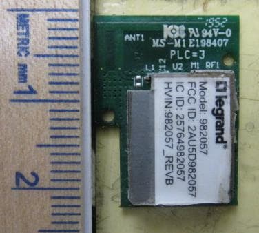
Click to zoom
Application Details
- Equipment Class
- DTS - Digital Transmission System
- Date of Grant
- Jun 07, 2020
- Application Purpose
- Original Equipment
- Date of Application
- Jun 04, 2020
- Equipment Note
- 982057 Module
- Frequency Range
- 2405.00000000 - 2475.00000000
- Company
- Legrand/Pass & Seymour
- Country
- United States
Documents & Files
Document Text
Text extracted from the exhibit documents filed with the FCC. Open a document above to read the original.
Users Manual
No: 341278 4/20 radiant ® WZ3RL10 Smart Switch, Zigbee 3.0, Incandescent, Halogen, Incandescent: 1800W Resistive: 120VAC, 60Hz, 15A; Standard + Electronic Ballast: 15A; Motor: 1/2 HP Interrupteur intelligent WZ3RL10, radiant® , module Zigbee 3.0, incandescent, halogène, incandescent : 1800 W Résistif : 120 V c. a., 60 Hz, 15 A; ballast standard/électronique : 15 A; moteur : 1/2 HP radiant® Interruptor inteligente WZ3RL10, Zigbee 3.0, incandescente, halógeno, Incandescente: 1800 W Resistivo: 120 VCA, 60 Hz, 15 A; Balasto estándar + electrónico: 15 A; Motor: 1/2 HP Installation Instructions • Notice d’Installation • Instrucciones de Instalación Catalog Number(s) • Numéro(s) de Catalogue • Les Numéros de Catalogue : WZ3RL10 Country of Origin: Made in China • Pays d’origine: Fabriqué en Chine • País de origen: Hecho en China 1-POLE Gr ound WHITE HO T OFF ON OFF ON OFF ON Load Red Green Bare Supply Hot WZ3RL10 Smart Switch Zigbee 3.0 BEFORE YOU START Review this guide in its entirety. Consult an electrician with any questions or if you are unsure of your abilities. Warning: Incorrect installation could result in death, serious injury, and/or damage to your home or devices. Caution: To reduce the risk of injury and/or overheating and damage to other equipment: • For dry, indoor use only. • Do not use to power medical equipment – not suitable as a disconnecting means. • Do not use with loads exceeding the device load rating. • Connect the smart switch to a 120 VAC, 60 Hz power source ONLY. • Always use copper wire to install the smart switch & follow all applicable local & national electrical codes. WHAT YOU NEED Required: • Phillips-head screwdriver • Flat blade screwdriver You May Also Need: Voltage tester, pliers, wire cutter, wire stripper, electrical tape, flashlight, wiring leads (included), and wire nuts (included). INSTALLATION & SETUP 1. Turn off power to device at circuit breaker Flip existing light switch multiple times to confirm power is off. NOTE: Ensure power is off to all devices in electrical box. 2. Remove existing device Check for the following wires: a. HOT or LINE: Receives power from the circuit box. Referred to as “hot” for the purpose of this guide. Do not touch or let “hot” wire contact other wires. b. LOAD: Directs power to your light(s). c. NEUTRAL: Creates a path to return current to the power source when the device is off. Required for your switch installation. d. GROUND: Provides a safe path for electricity in the even of a short circuit. 3. Wire Smart Switch Use the wire nuts provided to secure the wires together. a. Connect the WHITE neutral wire on the switch to the neutral wires in the box, using the red wire nut. b. Connect the LOAD wire on the switch to the load wire(s) in the box. c. Connect the HOT wire on the switch to the hot wire(s) in the box. d. Connect the GREEN ground wire on the switch to the ground wire(s) in the box. e. If the light is controlled with the only switch, use a wire nut to cap the YELLOW traveller wire on the device and proceed to step 4. 4. Secure Smart Switch a. Fold the wires into electrical box, taking care not to pinch a wire. b. Use included screws to secure smart switch to electrical box. Do not fully tighten the screws. 5. Test The Smart Switch NOTE: See getting to know your switch section for feature details. Turn the power back on at the circuit breaker, press switch to turn light on/ off. This device is designed to work with a Zigbee hub. Press the EZ button, the LED indicator will blink magenta to indicate commissioning mode. Follow the instructions from your hub to commission the device. If the switch is enrolled successfully, the LED will stop blinking. TROUBLESHOOTING TIP: If the device is not powering check wiring to determine if you have reversed the “HOT” and “LOAD” wiring. 6. Attach Wall Plate a. Use the sub-plate screws (provided) to secure the sub-plate to the smart switch. b. Tighten device screws to secure smart switch to the electrical box. c. Angle the UP end of the wall plate over the top edge of the sub-plate. Push the screwless wall plate down and in until it “snaps” into place over the sub-plate. NOTE: To remove the wall plate, place the tip of a flat blade screwdriver into the slot under the wall plate and twist gently. 7. Set Up Your System For more information on this product please see this link, or scan the QR code. https://www.legrand.us/radiant/products/smart- lighting/wz3rl10wh.aspxg G GETTING TO KNOW YOUR SWITCH ItemNameDescription 1Paddle Switch Press the top of the paddle to turn light on and the bottom of paddle to turn light off. 2LED Loca- tor Light Indicates the current state of device. Refer to “LED Locator Light Explanations” for detail. 3EZ ButtonUsed to start commis- sioning. LED Locator Light Explanations State of LightExplanation Solid WhiteLit when load is off. Solid RedFactory reset, not in network. Blinking MagentaDevice is attempting to connect to the network on all channels except 26. Solid MagentaDevice in network, temporarily open. Reset To Factory Default Deleting a device from the app will reset it to factory defaults. To manually reset the device to factory defaults press and hold the EZ button for 10 seconds until you see the LED blink red then release. The LED will change to solid red when the reset is complete. SPECIFICATIONS Deleting a device from the app will reset it to factory defaults. To manually reset the switch to factory defaults press and hold the Off (-) button for 10 seconds until you see the LED blink then release.The device will reset in about 20 seconds after release. LoadRating Resistive120 VAC, 60 Hz, 15 A Incandescent/Halogen1800 W Ballast15 A standard/electronic Motor 1 / 2 HP Legrand reserves the right to change specifications without notice. OFF ON OFF ON OFF ON OFF ON OFF ON OFF ON OFF ON OFF ON VOLTAGE TESTER Load Supply Hot 12 1-POLE Gr ound WHITE HO T OFF ON OFF ON OFF ON Load Red Green Bare Supply Hot THIS SIDE OUT MOUNT OVER DEVICE THIS SID…
Text truncated - open the document above for the full version.
Cover Letter(s)
Legrand/ Pass & Seymour P.O. Box 4822, Syracuse, NY 13221 Phone (315) 468-8014 Fax (315) 634-2684 Kris.Glassford @legrand.us Request for Confidentiality Date: _5/15/2020__ Subject: Confidentiality Request for: FCC ID: 2AU5D982057; IC: 25764-982057 Pursuant to FCC 47 CFR 0.457(d) and 0.459 and IC RSP-100, Section 12.4, the applicant requests that a part of the subject FCC application be held confidential. Type of Confidentiality Requested Exhibit ☐ Short Term ☒ Permanent Block Diagrams ☐ Short Term External Photos ☐ Short Term ☐ Permanent * 1 Internal Photos ☐ Short Term ☒ Permanent Operation Description/Theory of Operation ☐ Short Term ☐ Permanent Parts List & Placement/BOM ☐ Short Term ☐ Permanent Tune-Up Procedure ☐ Short Term ☒ Permanent Schematics ☐ Short Term Test Setup Photos ☐ Short Term ☐ Permanent * 3 User’s Manual Legrand Pass & Seymour has spent substantial effort in developing this product and it is one of the first of its kind in industry. Having the subject information easily available to "competition" would negate the advantage they have achieved by developing this product. Not protecting the details of the design will result in financial hardship. Permanent Confidentiality: The applicant requests the exhibits listed above as permanently confidential be permanently withheld from public review due to materials that contain trade secrets and proprietary information not customarily released to the public. Short-Term Confidentiality: The applicant requests the exhibits selected above as short term confidential be withheld from public view for a period of 0 days from the date of the Grant of Equipment Authorization and prior to marketing. This is to avoid premature release of sensitive information prior to marketing or release of the product to the public. Applicant is also aware that they are responsible to notify ACB in the event information regarding the product or the product is made available to the public before the requested period has expired. ACB will then release the documents listed above for public disclosure pursuant to FCC Public Notice DA 04-1705. NOTE for Industry Canada Applications: IC currently only distinguishes Permanent Confidentiality exhibits as shown above. Short Term confidentiality is not considered applicable to IC applications. Sincerely, By: 1 - The asterisked items (*) require further information to be provided to ACB before permanent confidentiality will be extended to these exhibits. Please refer to FCC KDB 726920 and the specific Document link for D01 found at: https://apps.fcc.gov/oetcf/kdb/forms/FTSSearchResultPage.cfm?switch=P&id=41731 and review section II, 3) regarding specific information that must accompany these requests.
Cover Letter(s)
Legrand/ Pass & Seymour P.O. Box 4822, Syracuse, NY 13221 Phone (315) 468-8014 Fax (315) 634-2684 Kris.Glassford @legrand.us Request for Modular/Limited Modular Approval Date: May 16, 2020 Subject: Manufacturer’s Declaration for ☐ - Modular Approval ☐ - Split Modular Approval ☒ - Limited Modular Approval ☐ - Limited Split Modular Approval Confidentiality Request for: _FCC ID: 2AU5D982057_______ 8 Basic Requirements – FCC Part 15.212(a)(1) For Items Marked “NO(*)”, the Limited Module Description Must be Filled Out on the Following Pages Modular Approval Requirement Requirement Met 1. The modular transmitter must have its own RF shielding. This is intended to ensure that the module does not have to rely upon the shielding provided by the device into which it is installed in order for all modular transmitter emissions to comply with FCC limits. It is also intended to prevent coupling between the RF circuitry of the module and any wires or circuits in the device into which the module is installed. Such coupling may result in non-compliant operation. The physical crystal and tuning capacitors may be located external to the shielded radio elements. 15.212(a)(1)(i) ☒ - YES ☐ - NO(*) Details: The module contains a metal shield which covers all RF components and circuitry. The shield is located on the top of the board. 2. The modular transmitter must have buffered modulation/data inputs (if such inputs are provided) to ensure that the module will comply with FCC requirements under conditions of excessive data rates or over-modulation. 15.212(a)(1)(ii) ☒ - YES ☐ - NO(*) Details: Data to the modulation circuit is buffered as described in the operational description provided with the application. 3. The modular transmitter must have its own power supply regulation on the module. This is intended to ensure that the module will comply with FCC requirements regardless of the design of the power supplying circuitry in the device into which the module is installed. 15.212(a)(1)(iii) ☒ - YES ☐ - NO(*) Details: The module contains its own power supply regulation. Please refer to schematic filed with this application. 4. The modular transmitter must comply with the antenna and transmission system requirements of §§ 15.203, 15.204(b), 15.204(c), 15.212(a), and 2.929(b). The antenna must either be permanently attached or employ a ‘‘unique’’ antenna coupler (at all connections between the module and the antenna, including the cable). The ‘‘professional installation’’ provision of § 15.203 is not applicable to modules but can apply to limited modular approvals under paragraph 15.212(b). 15.212(a)(1)(iv) ☒ - YES ☐ - NO(*) Details: The module contains a fixed inverted F antenna formed with 1oz copper on a 0.031 inch thick FR-4 pcb. 5. The modular transmitter must be tested in a stand-alone configuration, i.e., the module must not be inside another device during testing. This is intended to demonstrate that the module is capable of complying with Part 15 emission limits regardless of the device into which it is eventually installed. Unless the transmitter module will be battery powered, it must comply with the AC line conducted requirements found in Section 15.207. AC or DC power lines and data input/output lines connected to the module must not contain ferrites, unless they will be marketed with the module (see Section 15.27(a)). The length of these lines shall be length typical of actual use or, if that length is unknown, at least 10 centimeters to insure that there is no coupling between the case of the module and supporting equipment. Any accessories, peripherals, or support equipment connected to the module during testing shall be unmodified or commercially available (see Section 15.31(i)). 15.212(a)(1)(v) ☒ - YES ☐ - NO(*) Details: The module was tested stand-alone as shown in test setup photographs filed with this application. Legrand/ Pass & Seymour P.O. Box 4822, Syracuse, NY 13221 Phone (315) 468-8014 Fax (315) 634-2684 Kris.Glassford @legrand.us Modular Approval Requirement Requirement Met 6. The modular transmitter must be labeled with its own FCC ID number, or use an electron display (see KDB Publication 784748). If using a permanently affixed label with its own FCC ID number, if the FCC ID is not visible when the module is installed inside another device, then the outside of the device into which the module is installed must also display a label referring to the enclosed module. This exterior label can use wording such as the following: “Contains Transmitter Module FCC ID: XYZMODEL1” or “Contains FCC ID: XYZMODEL1.” Any similar wording that expresses the same meaning may be used. The Grantee may either provide such a label, an example of which must be included in the application for equipment authorization, or, must provide adequate instructions along with the module which explain this requirement. In the latter case, a copy of these instructions must be included in the application for equipment authorization. If the modular transmitter uses an electronic display of the FCC identification number, the information must be readily accessible and visible on the modular transmitter or on the device in which it is installed. If the module is installed inside another device, then the outside of the device into which the module is installed must display a label referring to the enclosed module. This exterior label can use wording such as the following: “Contains FCC certified transmitter module(s).” Any similar wording that expresses the same meaning may be used. The user manual must include instructions on how to access the electronic display. A copy of these instructions must be included in the application for equipment authorization. 15.212(a)(1)(vi) ☒ - YES ☐ - NO(*) Details: There is a label on the module as shown in the labeling exhibit filed with this application. 7. The modular transmitter must comply with all specific rule or operating requirements applicable to the transmitter, including all the co…
Text truncated - open the document above for the full version.
Cover Letter(s)
Legrand/ Pass & Seymour P.O. Box 4822, Syracuse, NY 13221 Phone (315) 468-8014 Fax (315) 634-2684 Kris.Glassford @legrand.us Date: June 4, 2020 Subject: Limited Modular Approval for FCC ID: 2AU5D982057 / IC: 25764-982057 To Whom It May Concern: Pass & Seymour, Inc d/b/a Legrand is seeking LMA approval of the 982057 Module. The module is approved ONLY for use by Pass & Seymour, Inc d/b/a Legrand in our products, and the module is not intended for sale to the third parties. Therefore, the OEM Integration Manual Guidance per KDB 996369 D03 is found in the Theory of Operation and the integration instructions are internal confidential documents. Thank you, By: ___Kris Glassford_____________ (Print name) Title: ____Lab Testing and Certification Manager___ On behalf of: __Pass & Seymour Inc d/b/a Legrand________ (Company Name) Telephone: _____(315) 468-8014____________________
External Photos
EXTERNAL PHOTOS Company Name Pass & Seymour, Inc d/b/a Legrand Model # 982057 FCC ID # 2AU5D982057 IC # 25764-982057 Page 1 of 2 EXTERNAL PHOTOS Company Name Pass & Seymour, Inc d/b/a Legrand Model # 982057 FCC ID # 2AU5D982057 IC # 25764-982057 Page 2 of 2
ID Label/Location Info
(Calipers are nominal values.) Facestock Adhesive Liner 2.0 mil (51 micron) 0.8 mil (20 micron)3.2 mil (81 micron) Gloss radiant white polyester#310 Acrylic55# Densified kraft 3 Thermal Transfer Polyester Label Material 7816 Features • Facestock is topcoated for thermal transfer printing. Resin ribbons are recommended for optimum durability. The topcoat also provides improved ink anchorage for traditional forms of press printing. • #310 adhesive is a firm adhesive which resists oozing and provides high strength on a variety of surfaces including high surface energy (HSE) plastics and metals. • 55# densified kraft liner assures consistent die cutting. • 3M™ Label Material 7816 is UL recognized (File MH16411) and CSA accepted (File 99316). See the UL and CSA listings for details. Technical DataFebruary 1, 1999 Application Ideas• Barcode labels and rating plates. • Property identification and asset labeling. • Warning, instruction, and service labels for durable goods. • Nameplates for durable goods. Construction FOD# 1606 page 1 of 5 Supersedes July 31, 1996 3M ™ Thermal Transfer Polyester Label Material 7816 Typical Physical Properties Note: The following technical information and data should be considered representative or typical only and should not be used for specification purposes. Adhesion: 180°peel test procedure is ASTM D 3330. 90°peel test procedure is ASTM D 3330 modified for the angle change. InitialConditioned for 3 Days at Room (10 Minute Dwell/RT)Temperature 72°F (22°C) 180°Peel90°Peel180°Peel90°Peel SurfaceOz./In.N/100 mmOz./In.N/100 mmOz./In.N/100 mmOz./In.N/100 mm Stainless Steel4347353851564145 Polycarbonate4751374052574347 Polypropylene1820161818202426 Glass5257343768744751 HD Polyethylene2426161833362022 LD Polyethylene2022121332352224 Conditioned for 3 Days at Conditioned for 24 hours at 90°F 120°F (49°C)(32°C) at 90% Relative Humidity 180°Peel90°Peel180°Peel90°Peel SurfaceOz./In.N/100 mmOz./In.N/100 mmOz./In.N/100 mmOz./In.N/100 mm Stainless Steel6066465074814650 Polycarbonate4145323562684044 Polypropylene3538303338422730 Glass6874424666723235 HD Polyethylene3033202235382730 LD Polyethylene548920222426 Liner Release: 180°Removal of Liner from Facestock Rate of RemovalGrams/Inch WidthN/100 mm 90 inches/minute110.42 300 inches/minute110.42 FOD#1606 page 2 of 5 3M ™ Thermal Transfer Polyester Label Material 7816 Environmental Performance The properties defined are based on four hour immersions at room temperature (72°F/22°C) unless otherwise noted. Samples were applied to stainless steel panels 24 hours prior to immersion and were evaluated one hour after removal from the solution for peel adhesion. Adhesion measured at 180°peel angle (ASTM D 3330) at 12 inches/minute. Chemical Resistance: Adhesion to Stainless Steel AppearanceEdge Penetration ChemicalOz./in.N/100 mmVisualMillimeters Isopropyl Alcohol5459No change1 Detergent (1% Alconox ® *)6672No change0 Engine Oil (10W30) @ 250°F (121°C)7077No change1.5 Water for 48 hours7279No change0 pH 47077No change0 pH 106672No change0 409 ® * Cleaning solution6571No change0 Toluene2932No change6.3 Acetone3842No change4.5 Brake Fluid7784No change0 Gasoline3235No change5.5 Diesel Fuel5560No change1 Mineral Spirits4852No change2.3 Hydraulic Fluid5863No change0 Temperature Resistance: 300°F (149°C) for 24 hours: no significant visual change 0.7% MD shrinkage 0.8% CD shrinkage -40°F (-40°C) for 10 days: no significant visual change Humidity Resistance: 24 hours at 100°F (38°C) and 100% relative humidity: no significant change in appearance or adhesion Accelerated Aging: ASTM D 3611: 96 hours at 150°F (65°C) and 80% relative humidity Rate of RemovalGrams/Inch WidthN/100 mm 180°Removal of Liner90 inches/minute110.42 from Facestock Rate of RemovalOz./In. WidthN/100 mm 180°Peel Adhesion 12 inches/minute491.89 from Stainless Steel FOD#1606 page 3 of 5 3M ™ Thermal Transfer Polyester Label Material 7816 FOD#1606 page 4 of 5 Shelf LifeTwo years from date of manufacture of product when properly stored at 72°F (22°C) and 50% relative humidity. Agency Listing Information Thermal Transfer Printing Printer: UL no longer requires evaluation and listing of specific printers. *Ink Ribbon/UL Recognized Components Advent: 301 Black; 303 Black; 501 Black; 501 Red; 501 Blue; 501 Green Armor: AXR-7; AXR-7+; AXR-600 Astromed™: R5 CP™: 5440 Red; 5640 Blue; 5940 Black Dasco: DR-74; DR-84 Great Ribbon: SDR ICS: ICS-CC-4099.1 Iimak™: SH-36; SP-330; PrimeMark Intermec: 053258-2; 054048-4 Japan Pulp and Paper: JP Resin 1; JP Resin 2 Blue; JP Resin 2 Red (suitable for indoor use only); JP Resin 2 Green (suitable for indoor use only) Kurz™: K500; K501 Markem™: 716 (suitable for indoor use only) Mid City Columbia™: CGL-80; CGL-80HE NCR™: Matrix Resin; Matrix; PaceSetter; Promark II; Ultra V Pelikan™: T016 Ricoh™: B110A; B110C; B110CX Sato™: Premier 1 Sony™: 4070; 4072; 4075; 4085; 5070; Signature™Series Resin; Signature™Series Wax UBI™: HR03; HR04 Zebra™: 5095; 5099; 5100; 5175 3 Industrial Tape and Specialties Division 3M Center, Building 220-7W-03 St. Paul, MN 55144-1000 USA 1 800 362 3550 1 800 223 7427 Fax On Demand www.3M.com Except where prohibited by law, 3M will not be liable for any loss or damage arising from the 3M product, whether direct, indirect, special, incidental, or consequential, regardless of the legal theory asserted, including contract, warranty, negligence, or strict liability. Limitation of Liability The 3M product will be free from defects in material and manufacture for a period of one (1) year from the date of manufacture. 3M MAKES NO OTHER WARRANTIES OR CONDITIONS, INCLUDING, BUT NOT LIMITED TO, ANY IMPLIED WARRANTY OF MERCHANTABILITY OR FITNESS FOR A PARTICULAR PURPOSE OR ANY IMPLIED WARRANTY ARISING OUT OF A COURSE OF DEALING, CUSTOM, OR USAGE OF TRADE.User is responsible for determining whether the 3M product is fit for a particular purpose and suitable for user’s method of application. If the 3M product is defective within the warr…
Text truncated - open the document above for the full version.
Internal Photos
INTERNAL PHOTOS Company Name Pass & Seymour, Inc d/b/a Legrand Model # 982057 FCC ID # 2AU5D982057 IC # 25764-982057 Page 1 of 1
RF Exposure Info
A Company: Pass & Seymour, Inc. d/b/a Legrand Page 1 of 12 Name: 982057 Report: TR 319197 C Model: 982057 Job: C-3272 Serial: Engineering Sample Test Report # 319197 C (RFx) Equipment Under Test: 982057 Test Date(s): December 3 rd , 2019 Prepared for: Pass & Seymour, Inc. d/b/a Legrand Attn: Joshua Haines 50 Boyd Avenue Syracuse, NY 13209 Report Issued by: Zach Wilson, EMC Engineer Signature: Date: 5/18/2020 Report Reviewed by: Adam Alger, Quality Manager Signature: Date: 5/18/2020 Report Constructed by: Zach Wilson, EMC Engineer Signature: Date: 5/18/2020 This test report may not be reproduced, except in full, without approval of Laird Connectivity, Inc. Company: Pass & Seymour, Inc. d/b/a Legrand Page 2 of 12 Name: 982057 Report: TR 319197 C Model: 982057 Job: C-3272 Serial: Engineering Sample CONTENTS Contents ........................................................................................................................................................ 2 Laird Connectivity Test Services in Review ............................................................................................... 3 1 Test Report Summary ........................................................................................................................... 4 2 Client Information ................................................................................................................................. 5 2.1 Equipment Under Test (EUT) Information .................................................................................... 5 2.2 Product Description ...................................................................................................................... 5 2.3 Modifications Incorporated for Compliance ................................................................................. 5 2.4 Deviations and Exclusions from Test Specifications ..................................................................... 5 2.5 Radio Programming ...................................................................................................................... 5 2.6 EUT Power ..................................................................................................................................... 5 3 References ............................................................................................................................................ 6 4 Uncertainty Summary ........................................................................................................................... 7 5 Test Data ............................................................................................................................................... 8 5.1 Zigbee Fundamental Emission ...................................................................................................... 8 6 Exclusion Calculation........................................................................................................................... 10 6.1 FCC .............................................................................................................................................. 10 6.2 ISED Canada ................................................................................................................................ 11 7 Revision History .................................................................................................................................. 12 Company: Pass & Seymour, Inc. d/b/a Legrand Page 3 of 12 Name: 982057 Report: TR 319197 C Model: 982057 Job: C-3272 Serial: Engineering Sample Laird Connectivity Test Services in Review The Laird Technologies, Inc. laboratory located at W66 N220 Commerce Court Cedarburg, Wisconsin, 53012 USA is recognized through the following organizations: A2LA – American Association for Laboratory Accreditation Accreditation based on ISO/IEC 17025:2017 with Electrical (EMC) Scope A2LA Certificate Number: 1255.01 Scope of accreditation includes all test methods listed herein unless otherwise noted Federal Communications Commission (FCC) – USA Accredited Test Firm Registration Number: 953492 Recognition of two 3 meter Semi-Anechoic Chambers Innovation, Science and Economic Development Canada Accredited U.S. Identification Number: US0218 Recognition of two 3 meter Semi-Anechoic Chambers Company: Pass & Seymour, Inc. d/b/a Legrand Page 4 of 12 Name: 982057 Report: TR 319197 C Model: 982057 Job: C-3272 Serial: Engineering Sample 1 TEST REPORT SUMMARY During December 3 rd , 2019 the Equipment Under Test (EUT), 982057, as provided by Pass & Seymour, Inc. d/b/a Legrand was tested to the following requirements of the Federal Communications Commission and Innovation, Science and Economic Development Canada : Test Requirements Description Specification Method Compliant RSS-102 Radio Frequency Exposure Compliance of Radiocommunication Apparatus Reported RSS-102 Section 2.5.2 Reported FCC Part 1.1307, 2.1091, 2.1093 RF Exposure and equipment authorization requirements Reported FCC KDB 447498 D01 Reported Notice: The results relate only to the item tested as configured and described in this report. Any additional configurations, modes of operation, or modifications made to the equipment under test after the specified test date(s) are at the decision of the client and may not apply to the data seen in this test report. The decision rule for Pass / Fail assessment to the specification or standard listed in this test report has been agreed upon by the client and laboratory to be as follows: Measurement Type Rule Emissions – Amplitude N/A Emissions – Frequency N/A Immunity N/A Company: Pass & Seymour, Inc. d/b/a Legrand Page 5 of 12 Name: 982057 Report: TR 319197 C Model: 982057 Job: C-3272 Serial: Engineering Sample 2 CLIENT INFORMATION Company Name Pass & Seymour, Inc. d/b/a Legrand Contact Person Joshua Haines Address 50 Boyd Avenue Syracuse, NY 13209 2.1 Equipment Under Test (EUT) Information The following information has been supp…
Text truncated - open the document above for the full version.
Test Report
A Company: Pass & Seymour, Inc. d/b/a Legrand Page 1 of 33 Name: 982057 Report: TR 319197 A Model: 982057 Job: C-3272 Serial: Engineering Sample Test Report # 319197 A Equipment Under Test: 982057 Test Date(s): November 25 th , 2019– April 7 th , 2020 Prepared for: Pass & Seymour, Inc. d/b/a Legrand Attn: Joshua Haines 50 Boyd Avenue Syracuse, NY 13209 Report Issued by: Zach Wilson, EMC Engineer Signature: Date: 5/12/2020 Report Reviewed by: Adam Alger, Quality Manager Signature: Date: 4/9/2020 Report Constructed by: Zach Wilson, EMC Engineer Signature: Date: 4/7/2020 This test report may not be reproduced, except in full, without approval of Laird Connectivity, Inc. Company: Pass & Seymour, Inc. d/b/a Legrand Page 2 of 33 Name: 982057 Report: TR 319197 A Model: 982057 Job: C-3272 Serial: Engineering Sample CONTENTS Contents ........................................................................................................................................................ 2 Laird Connectivity Test Services in Review ............................................................................................... 3 1 Test Report Summary ........................................................................................................................... 4 2 Client Information ................................................................................................................................. 5 2.1 Equipment Under Test (EUT) Information .................................................................................... 5 2.2 Product Description ...................................................................................................................... 5 2.3 Modifications Incorporated for Compliance ................................................................................. 5 2.4 Deviations and Exclusions from Test Specifications ..................................................................... 5 2.5 Radio Programming ........................…
Text truncated - open the document above for the full version.
Contact Information
Applicant
Kris Glassford(Testing Lab & Certification Manager)
Test Firm
Laird Connectivity LLCAdam Alger
Technical Specifications
| # | Rule Parts | Frequency Range | Power Output |
|---|---|---|---|
| 1 | 15C | 2.40 GHz - 2.48 GHz | 4.00 mW |
Other Applications from Legrand/Pass & Seymour
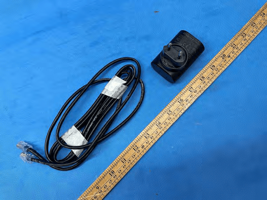
2AU5D-LXX12
Aug 09, 2021Wireless Charging Pad
Equipment Class
DCD - Part 15 Low Power Transmitter Below 1705 kHz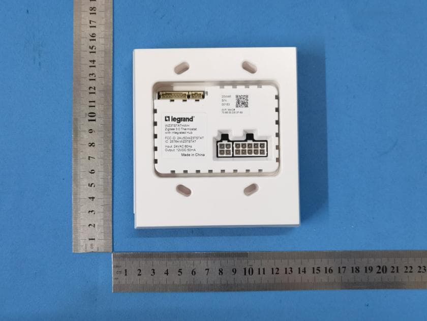
2AU5DWZ3TSTAT
Jun 28, 2021Thermostat
Equipment Class
DTS - Digital Transmission System
2AU5D-WNRH1
Mar 11, 2021Smart Gateway with Netatmo
Equipment Class
DTS - Digital Transmission System