2AU8HSRP410-BLTE CPE
Smawave Technology Co. ,Ltd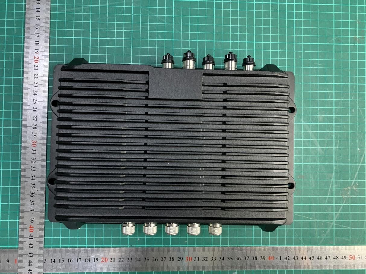
Click to zoom
Application Details
- Equipment Class
- DTS - Digital Transmission System
- Date of Grant
- Aug 19, 2020
- Application Purpose
- Original Equipment
- Date of Application
- Aug 19, 2020
- Equipment Note
- LTE CPE
- Frequency Range
- 2412.00000000 - 2462.00000000
- Company
- Smawave Technology Co. ,Ltd
- Country
- China
Documents & Files
Document Text
Text extracted from the exhibit documents filed with the FCC. Open a document above to read the original.
Users Manual
Use a cross screwdriver to remove the SIM card cover. Slide the SIM cards into the SIM card slots until they click into place. By default, the SIM card in slot 1 (the upper slot) is the Primary SIM card. When the SRP router is powered on or reboots, it automatically connects to the network associated with the Primary SIM card. Re-attach the cover. SRP Series Quick Start Guide Welcome to the SRP Series Smawave SRP series ruggedized outdoor CPE provides LTE service in a ruggedized form factor. With an operating temperature range of -40°C to +70°C endurance, they offer industrial-grade environmental qualifications while providing higher speeds data services for video and other bandwidth-intensive applications. SRP series industrial CPE has very strong anti-vibration ability and it is qualified for extreme industrial environments and ideally suited for rail, transportation, mining, oil and gas, manufacturing, and other outdoor applications. With the diverse self-developed LTE-A embedded modules integrated, SRP series industrial CPE can support multi-bands for Private LTE, even support uncommon frequencies. SRP series industrial CPE can provide accurate real-time location information. The built-in GNSS receiver supports GPS, GLONASS, BEIDOU and Galileo constella- tions. This document will serve as a quick start guide for SRP series ruggedized outdoor CPE. In this document, the SRP series ruggedized outdoor CPE will be replaced by the CPE. Carefully read the following safety symbols to help you use your CPE safely and correctly. Equipment Appearance The reset button is beside SIM interface, if press 1s, CPE will restart; if press above 10s, CPE will factory reset. There are two white ground screws also at behind of device. Note1 Step1 Step2 Step3 Note2 RS232/485 Cable Definition M12 RS232/485 cable definition NumberColorsRS485RS232+DIDO 8 7 6 5 4 3 2 1 BrownRS485_ARS232_RX RS232_TX RS_GND RS_GND DI1 DO1 DI2 DO2 RS485_B RS_GND RS_GND RS_GND RS_GND NC NC Brown&white Green Blue&white Blue Green&white Orange Orange&white Working Environment Power Supply 9~36VDC Power Consumption Water and Dustproof 12W IP67 Operating Storage Humidity -40°C~ 70°C -40°C~80°C 5%~95% Packing List M12 A-Code cable to RJ45 jack ADC2 Ethernet cable ItemsAccessoriesQty M12 A-Code 8Pin cable ADB1Data cable M12 A-Code 4Pin cable M12APower cable Mounting bolts (M5*20) Grounding cable M12 Protective cap TNC protective cap 1 2 3 4 5 6 7 1 1 1 4 1 5 3/5 Configure Hardware Install SIM Cards Connect and Turn on the Router 3.Connect the WIFI1 antennas and WIFI2 if applicable. 1.Connect the ANT1 and ANT2 Cellular antennas. 2.Connect the GPS antenna if applicable. 5.Connect a computer to the router with an Ethernet cable. 6.Connect 9-36 VDC power cable. 7.Connect devices to the RS232/RS485/DIDO ports. Connect to the Network When the router is powered on, a green PWR LED may occur. This indicates that the power input is good. Once the router’s radio module is configured for the SIMcard, it begins the activation/provisioning process and attempts to connect to the mobile network. This process typically takes several minutes. A successful connection is indicated by a solid green NET LED. And the strength of the RF signal can be indicated by the RSSI LED in different colors. 12345 6 4.Connect the protecting ground cable. Green Off Green Off Green Yellow Red Off Power on No power supply Register to network Not register to network Signal strong Signal good Signal weak No signal PWR NET RSSI Login to the Web Management Page Launch the web browser, enter http://192.168.0.1 in the address bar, and press Enter. Enter the user name and password, and click Log In. You can login to the web management page after the password is verified. Configure Software Step1 Step2 Step3 The default user name and password are both admin. If you want to view or configure the CPE more, you should use the super account to log in to the web management page. The default super user name is superadmin, and the password is admin. LTE Settings To set the LTE network, perform the following steps: Choose Network >LTE Settings; In the Settings area, you can set the configuration of LTE network; In the Status area, you can view the LTE network connect status, such as Frequency, RSSI, RSRP, RSRQ,CINR, SINR, Cell ID and so on. Step1 Step2 Step3 FAQs The POWER indicator does not turn on. Make sure that the power cable is connected proper- ly and the CPE is powered on. Make sure that the power adapter is compatible with the CPE. Fails to Login the web management page. Make sure that the CPE is started. WLAN Settings Choose Settings Wi-Fi WLAN Settings. In the General Settings area, set Wi-Fi Enable or enable Wi-Fi. In the Setting area, change the SSID, such as "LTE-Router". To ensure data security, it is recommended that you change the Wi-Fi password . Click Submit to save the settings. Step1 Step2 Step3 Step4 Step5 Verify that the CPE is correctly connected to the computer through Wi-Fi or a network cable. If the problem persists, contact authorized local service suppliers. The CPE fails to search for the wireless network. Check that the power adapter is connected properly. Check that the CPE is placed in an open area that is far away from obstructions, such as concrete or wooden walls. Check that the CPE is placed far away from household electrical appliances that generate strong electromagnetic field, such as microwave ovens, refrigera- tors, and satellite dishes. If the problem persists, contact authorized local service suppliers. The parameters are restored to default values. If the CPE powers off unexpectedly while being configured, the parameters may be restored to the default settings. After configuring the parameters, download the configuration file to quickly restore the CPE to the desired settings. The CPE do not support SIM card hot-plug, please confirm that the device has been powered off when the SIM card is inserted or removed. 7 8 91011 FCC Regulations: This dev…
Text truncated - open the document above for the full version.
Cover Letter(s)
Company:ShanghaiSmawaveTechnologyCo.,Ltd Date:2020/8/17 DTS-UNIIDeclarationLetter Towhomitmayconcern WehavedeclaredbelowfeaturedforFCCequipmentauthorization. DeviceFCCID:2AU8HSRP410-B 1.Active/PassiveScanning,adHocmodeaccesspointcapability 2412-2462MHz 区 yes 口 No 区 yes 口 No 口 yes 区 No 区 yes 口 No 5150-5250MHz 口 yes 区 No 区 yes 口 No 口 yes 区 No 口 yes 区 No 5725-5825MHz 口 yes 区 No 区 yes 口 No 口 yes 区 No 口 yes 区 No MeetFCCpart15.202/RSS-247,Issue2,Section6.4a)requirement-区Yes,口No plscheckbelow: 口Amasterdeviceisdefinedasadeviceoperatinginamodeinwhichithasthecapabilityto transmitwithoutreceivinganenablingsignal.Inthismodeisabletoselectachannelandinitiate anetworkbysendingenablingsignalstootherdevices 区Aclientdeviceisdefinedasadeviceoperatinginamodeinwhichthetransmissionsofthe deviceareundercontrolofthemaster.Adeviceinclientmodeisnotabletoinitiateanetwork.... Sincerely, Signature: Name(inprint):wangfei Company:ShanghaiSmawaveTechnologyCo.,Ltd Adreess:3FBuilding81001NorthQinzhouRoadXuhuiDistrictShanghai China
Cover Letter(s)
Declaration Herebywe, Nameofmanufacturer:ShanghaiSmawaveTechnologyCo.,Ltd Address:3/F,Building8,1001NorthQinzhouRoad,XuhuiDistrict,Shanghai, China Zipcode&City:Shanghai Country:China Telephonenumber:/ declarebelowproduct: Productdescription:LTECPE Typedesignation(s):SRP410-b FCCID:2AU8HSRP410-B Trademark:Smawave Whichassemblesthebelowmodules Productdescription:LTEmodule Typedesignation(s):MGL6213A Trademark:Smawave FCCID:2AU8HMGL6213A CanquotedirectlytheRFconductedtestreportofFCCcertification,andtheoriginal testreportsaccuratelyrepresenttestresultsontheSRP410-b.Becausethemoduleis embeddedintheSRP410-b,thendirectlyconnecttoantennatosentRFsignalto communicationnetwork,SothisdesignwillnotimpactthemoduleRFconnectedperformance andcanensuretheRFconductedtestresultisaccordancewithoriginalreportonthe newproduct.Pleaserefertobelowblockdiagramformoredetail. Signedforandonbehalfof: Date:17/8/2020 City:Shanghai PrintName:wangfei Signature: Company:ShanghaiSmawaveTechnologyCo.,Ltd
Cover Letter(s)
ShanghaiSmawaveTechnologyCo.,Ltd OfficeofEngineeringTechnology FederalCommunicationsCommission 7435OaklandMillsRoad Columbia,MD21046 Subject;RequestforLongTermConfidentiality FCCID:2AU8HSRP410-B ToWhomItMayConcern, PursuanttotheprovisionsoftheCommission’srulesTitle47Sections§0.457and§0.459,weare requestingtheCommissiontowithholdthefollowingattachment(s)asconfidentialdocumentsfrom publicdisclosureindefinitely. Thesedocumentscontaindetailedsystemandequipmentdescriptionsandareconsideredas proprietaryinformationinoperationoftheequipment.Thepublicdisclosureofthesedocuments mightbeharmfultoourcompanyandwouldgivecompetitorsanunfairadvantageinthemarket. SchematicDiagram BlockDiagram PartsList OperationalDescription Tune-upProcedure SoftwareSecurityDescription UNIIdeclarationletter Itisourunderstandingthatallmeasurementtestreports,FCCIDlabelformatandcorrespondence duringthecertificationreviewprocesscannotbegrantedasconfidentialdocumentsandthis informationwillbeavailableforpublicreviewoncethegrantofequipmentauthorizationisissued. Sincerely, Date:2020-4-29 Signature: Name(inprint):wangfei Company:ShanghaiSmawaveTechnologyCo.,Ltd Adreess:3FBuilding81001NorthQinzhouRoadXuhuiDistrictShanghaiChina
Cover Letter(s)
SmawaveTechnologyCo.,Ltd POWEROFATTORNEY DATE:August17,2020 To: FederalCommunicationsCommission, Authorization&EvaluationDivision, 7435OaklandMillsRoad, Columbia,MD21046 We,theundersigned,herebyauthorizeTATechnology(Shanghai)Co.,Ltd./zhaojunllinonour behalf,toapplytoFCConourequipmentforFCCID:2AU8HSRP410-B.Anyandallactscarriedout byTATechnology(Shanghai)Co.,Ltd.onourbehalfshallhavethesameeffectasactsofourown forthiscertificate. Sincerely, Date:2020-7-17 Signature: Name(inprint):wangfei Company:ShanghaiSmawaveTechnologyCo.,Ltd Adreess:3FBuilding81001NorthQinzhouRoadXuhuiDistrictShanghaiChina
External Photos
EUT Appearance Report No.: R2001A0016 TA Technology (Shanghai) Co., Ltd. Page 1 of 4 This report shall not be reproduced except in full, without the written approval of TA Technology (Shanghai) Co., Ltd. EUT Appearance EUT Appearance Report No.: R2001A0016 TA Technology (Shanghai) Co., Ltd. Page 2 of 4 This report shall not be reproduced except in full, without the written approval of TA Technology (Shanghai) Co., Ltd. EUT Appearance Report No.: R2001A0016 TA Technology (Shanghai) Co., Ltd. Page 3 of 4 This report shall not be reproduced except in full, without the written approval of TA Technology (Shanghai) Co., Ltd. a: EUT EUT Appearance Report No.: R2001A0016 TA Technology (Shanghai) Co., Ltd. Page 4 of 4 This report shall not be reproduced except in full, without the written approval of TA Technology (Shanghai) Co., Ltd. b: Antenna Picture 1: Constituents of EUT
ID Label/Location Info
LabelLocation Company: SmawaveTechnologyCo.,Ltd Model: SRP410-b LabelLocation Company: SmawaveTechnologyCo.,Ltd Model: SRP410-b Packagelabel
Internal Photos
SRP410-binternalphoto
Test Report
MPE TEST REPORT Applicant Shanghai Smawave Technology Co. ,Ltd FCC ID 2AU8HSRP410-B Product LTE CPE Brand Smawave Model SRP410-b Report No. R2001A0016-M1 Issue Date August 18, 2020 TA Technology (Shanghai) Co., Ltd. tested the above equipment in accordance with the requirements in FCC 47 CFR Part 1 1.1310. The test results show that the equipment tested is capable of demonstrating compliance with the requirements as documented in this report. Performed by: Yu Wang Approved by: Guangchang Fan TA Technology (Shanghai) Co., Ltd. No.145, Jintang Rd, Tangzhen Industry Park, Pudong Shanghai, China TEL: +86-021-50791141/2/3 FAX: +86-021-50791141/2/3-8000 MPE Test Report Report No.: R2001A0016-M1 TA Technology (Shanghai) Co., Ltd. TA-MB-01-013S Page 2 of 9 This report shall not be reproduced except in full, without the written approval of TA Technology (Shanghai) Co., Ltd. Table of Contents 1 Test Laboratory ............................................................................................................................... 3 1.1 Notes of the Test Report ......................................................................................................... 3 1.2. Test facility ............................................................................................................................ 3 1.3 Testing Location ...................................................................................................................... 3 1.4 Laboratory Environment .......................................................................................................... 4 2 Description of Equipment under Test .............................................................................................. 5 3 Maximum conducted output power (measured) and antenna Gain ................................................ 6 4 Test Result ..................................................................................................................................... 7 MPE Test Report Report No.: R2001A0016-M1 TA Technology (Shanghai) Co., Ltd. TA-MB-01-013S Page 3 of 9 This report shall not be reproduced except in full, without the written approval of TA Technology (Shanghai) Co., Ltd. 1 Test Laboratory 1.1 Notes of the Test Report This report shall not be reproduced in full or partial, without the written approval of TA technology (shanghai) co., Ltd.The results documented in this report apply only to the tested sample, under the conditions and modes of operation as described herein .Measurement Uncertainties were not taken into account and are published for informational purposes only. This report is written to support regulatory compliance of the applicable standards stated above. 1.2. Test facility FCC (Designation number: CN1179, Test Firm Registration Number: 446626) TA Technology (Shanghai) Co., Ltd. has been listed on the US Federal Communications Commission list of test facilities recognized to perform electromagnetic emissions measurements. 1.3 Testing Location Company: TA Technology (Shanghai) Co., Ltd. Address: No.145, Jintang Rd, Tangzhen Industry Park, Pudong Shanghai, China City: Shanghai Post code: 201201 Country: P. R. China Contact: Fan Guangchang Telephone: +86-021-50791141/2/3 Fax: +86-021-50791141/2/3-8000 Website: http://www.ta-shanghai.com E-mail: [email protected] MPE Test Report Report No.: R2001A0016-M1 TA Technology (Shanghai) Co., Ltd. TA-MB-01-013S Page 4 of 9 This report shall not be reproduced except in full, without the written approval of TA Technology (Shanghai) Co., Ltd. 1.4 Laboratory Environment Temperature Min. = 18C, Max. = 25 C Relative humidity Min. = 30%, Max. = 70% Ground system resistance < 0.5 Ambient noise is checked and found very low and in compliance with requirement of standards. Reflection of surrounding objects is minimized and in compliance with requirement of standards. MPE Test Report Report No.: R2001A0016-M1 TA Technology (Shanghai) Co., Ltd. TA-MB-01-013S Page 5 of 9 This report shall not be reproduced except in full, without the written approval of TA Technology (Shanghai) Co., Ltd. 2 Description of Equipment under Test Client Information Applicant Shanghai Smawave Technology Co. ,Ltd Applicant address 3/F, Building 8, 1001 North Qinzhou Road,Xuhui District, Shanghai, China Manufacturer Shanghai Smawave Technology Co. ,Ltd Manufacturer address 3/F, Building 8, 1001 North Qinzhou Road,Xuhui District, Shanghai, China General Technologies Model SRP410-b IMEI 862165040679399 Hardware Version SGL6010_V1.0 Software Version SG626U_V1.0.0 Date of Testing: March 27, 2020 ~ August 10, 2020 Note: 1. The EUT is sent from the applicant to TA and the information of the EUT is declared by the applicant. 2. All indications of Pass/Fail in this report are opinions expressed by TA Technology (Shanghai) Co., Ltd. based on interpretations and/or observations of test results. Measurement Uncertainties were not taken into account and are published for informational purposes only. Only wifi 2.4G and wifi 5G were tested for SRP410-b in this report. Data of LTE Band 46 refer to the MGM5608A Module report (Report No. : R2001A0004-M1V1). MPE Test Report Report No.: R2001A0016-M1 TA Technology (Shanghai) Co., Ltd. TA-MB-01-013S Page 6 of 9 This report shall not be reproduced except in full, without the written approval of TA Technology (Shanghai) Co., Ltd. 3 Maximum conducted output power (measured) and antenna Gain The numeric gain (G) of the antenna with a gain specified in dB is determined by Numeric gain (G)=10^(antenna gain/10) Band Maximum Conducted Output Power (dBm) Antenna Gain (dBi) Numeric gain (dBm) (mW) LTE Band 46 23.000 199.526 3.180 2.080 WiFi 2.4G 18.290 67.453 5.000 3.162 WiFi 5G 23.180 207.970 5.000 3.162 MPE Test Report Report No.: R2001A0016-M1 TA Technology (Shanghai) Co., Ltd. TA-MB-01-013S Page 7 of 9 This report shall not be reproduced except in full, without the written approval of TA Technology (Shanghai) Co., Ltd. …
Text truncated - open the document above for the full version.
Test Report
RF TEST REPORT Applicant Shanghai Smawave Technology Co. ,Ltd FCC ID 2AU8HSRP410-B Product LTE CPE Brand Smawave Model SRP410-b Report No. R2001A0016-R2 Issue Date August 12, 2020 TA Technology (Shanghai) Co., Ltd. tested the above equipment in accordance with the requirements in FCC CFR47 Part 15C (2019). The test results show that the equipment tested is capable of demonstrating compliance with the requirements as documented in this report. Performed by: Peng Tao Approved by: Kai Xu TA Technology (Shanghai) Co., Ltd. No.145, Jintang Rd, Tangzhen Industry Park, Pudong Shanghai, China TEL: +86-021-50791141/2/3 FAX: +86-021-50791141/2/3-8000 RF Test Report Report No.: R2001A0016-R2 TA Technology (Shanghai) Co., Ltd. TA-MB-04- 005R Page 2 of 75 This report shall not be reproduced except in full, without the written approval of TA Technology (Shanghai) Co., Ltd. TABLE OF CONTENT 1. Test Laboratory ............................................................................................................................ 4 1.1. Notes of the test report ......................................................................................................... 4 1.2. Test facility ........................................................................................................................... 4 1.3. Testing Location ................................................................................................................... 4 2. General Description of Equipment under Test .............................................................................. 5 2.1. Applicant and Manufacturer Information ............................................................................... 5 2.2. General information .............................................................................................................. 5 3. Applied Standards ........................................................................................................................ 6 4. Test Configuration ........................................................................................................................ 7 5. Test Case Results ........................................................................................................................ 9 5.1. Maximum output power ........................................................................................................ 9 5.2. 99% Bandwidth and 6dB Bandwidth .................................................................................. 13 5.3. Band Edge ......................................................................................................................... 19 5.4. Power Spectral Density ...................................................................................................... 22 5.5. Spurious RF Conducted Emissions .................................................................................... 35 5.6. Unwanted Emission ........................................................................................................... 39 5.7. Conducted Emission .......................................................................................................... 72 6. Main Test Instruments ................................................................................................................ 75 RF Test Report Report No.: R2001A0016-R2 TA Technology (Shanghai) Co., Ltd. TA-MB-04- 005R Page 3 of 75 This report shall not be reproduced except in full, without the written approval of TA Technology (Shanghai) Co., Ltd. Summary of measurement results Number Test Case Clause in FCC rules Verdict 1 Maximum conducted output power 15.247(b)(3) PASS 2 99% Bandwidth and 6 dB bandwidth 15.247(a)(2) PASS 3 Power spectral density 15.247(e) PASS 4 Band Edge 15.247(d) PASS 5 Spurious RF Conducted Emissions 15.247(d) PASS 6 Unwanted Emissions 15.247(d),15.205,15.209 PASS 7 Conducted Emissions 15.207 PASS Test Date:March 27, 2020 ~ August 10, 2020 Note: All indications of Pass/Fail in this report are opinions expressed by TA Technology (Shanghai) Co., Ltd. based on interpretations and/or observations of test results. Measurement Uncertainties were not taken into account and are published for informational purposes only. RF Test Report Report No.: R2001A0016-R2 TA Technology (Shanghai) Co., Ltd. TA-MB-04- 005R Page 4 of 75 This report shall not be reproduced except in full, without the written approval of TA Technology (Shanghai) Co., Ltd. 1. Test Laboratory 1.1. Notes of the test report This report shall not be reproduced in full or partial, without the written approval of TA technology (shanghai) co., Ltd. The results documented in this report apply only to the tested sample, under the conditions and modes of operation as described herein .Measurement Uncertainties were not taken into account and are published for informational purposes only. This report is written to support regulatory compliance of the applicable standards stated above. 1.2. Test facility FCC (Designation number: CN1179, Test Firm Registration Number: 446626) TA Technology (Shanghai) Co., Ltd. has been listed on the US Federal Communications Commission list of test facilities recognized to perform electromagnetic emissions measurements. A2LA (Certificate Number: 3857.01) TA Technology (Shanghai) Co., Ltd. has been listed by American Association for Laboratory Accreditation to perform electromagnetic emission measurement. 1.3. Testing Location Company: TA Technology (Shanghai) Co., Ltd. Address: No.145, Jintang Rd, Tangzhen Industry Park, Pudong City: Shanghai Post code: 201201 Country: P. R. China Contact: Xu Kai Telephone: +86-021-50791141/2/3 Fax: +86-021-50791141/2/3-8000 Website: http://www.ta-shanghai.com E-mail: [email protected] RF Test Report Report No.: R2001A0016-R2 TA Technology (Shanghai) Co., Ltd. TA-MB-04- 005R Page 5 of 75 This report shall not be reproduced except in full, without the written approval of TA Technology (Shangha…
Text truncated - open the document above for the full version.
Test Setup Photos
RF Test Setup Report No.: R2001A0016 TA Technology (Shanghai) Co., Ltd. TA-MB-04-005R Page 1 of 2 This report shall not be reproduced except in full, without the written approval of TA Technology (Shanghai) Co., Ltd. Part15C Test Setup 30MHz-1GHz 1GHz-18GHz Picture 1 Radiated Emission Test Setup RF Test Setup Report No.: R2001A0016 TA Technology (Shanghai) Co., Ltd. TA-MB-04-005R Page 2 of 2 This report shall not be reproduced except in full, without the written approval of TA Technology (Shanghai) Co., Ltd. Picture 2 Conducted Emission Test Setup
Contact Information
Applicant
Aliy Yang(Certification engineer)
Test Firm
TA Technology (Shanghai) Co., Ltd.Mr. Zhihui Liu
[email protected]86-21-50791141
Technical Specifications
| # | Rule Parts | Frequency Range | Power Output |
|---|---|---|---|
| 1 | 15C | 2.41 GHz - 2.46 GHz | 67.00 mW |
Other Applications from Smawave Technology Co. ,Ltd
2AU8HSRE620-BH
Jul 18, 20235G ODU_NA
Equipment Class
CBD - Citizens Band Category A and B Devices
2AU8HSPH420-BQ
Jan 17, 2023Industrial smart handheld terminal
Equipment Class
DXX - Part 15 Low Power Communication Device Transmitter
2AU8HSPH320-AQ
Jan 16, 2023Industrial smart handheld terminal
Equipment Class
DXX - Part 15 Low Power Communication Device Transmitter
2AU8HSRW410-CBRS
Jan 13, 2023CAT12 outdoor CPE
Equipment Class
CBD - Citizens Band Category A and B Devices
2AU8HSRT421-CBRS
Dec 21, 2022LTE Indoor
Equipment Class
CBD - Citizens Band Category A and B Devices