2AV29-B255Baby Monitor
Zhongshan Jesmay Electronics Co.,Ltd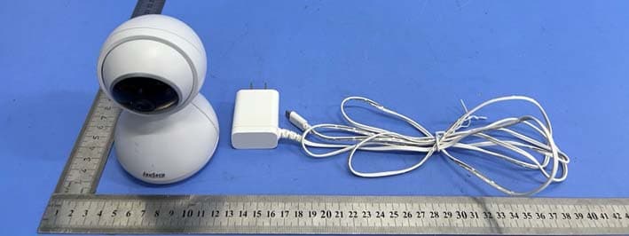
Click to zoom
Application Details
- Equipment Class
- DSS - Part 15 Spread Spectrum Transmitter
- Date of Grant
- Jun 10, 2022
- Application Purpose
- Original Equipment
- Date of Application
- Jun 10, 2022
- Equipment Note
- Baby Monitor
- Frequency Range
- 2410.00000000 - 2477.00000000
- Country
- China
Documents & Files
Document Text
Text extracted from the exhibit documents filed with the FCC. Open a document above to read the original.
Users Manual
WARNING STRANGULATION HAZARD Children have STRANGLED in cords. Keep this cord out of reach of children (more than 3 feet/1 meter away fr om the crib). Never use extension cords with AC adapters. Only use the AC Adapters pro vided. WARNING Adult assembly required. Keep small parts away from children when assembling. Warning Information Keep this instruc�on manual for future reference. For adult use only. WARNING Ba�ery Warning INSTRUCTION MANUAL Service Email: [email protected] Setup and use your video baby monitor Installing Baby Unit A. Place Baby Unit on a flat surface, such as a desk or shelf . 1 meter Never place the baby unit or the cord within 1 meter of the crib. Connect the small plug of the power adapter to the Baby Unit and the other end to a suitable electrical outlet. Only use the enclosed adapter (5V DC 1000mA). The baby unit is turned on and the power LED will be green. B. Menu mode (Press to select menu op�on) Press and hold to talk to baby unit. Talk Select OK VOX Precau�ons · Do not overload wall outlets, extension cords, or integral convenience receptacles as this can result in a risk of fire or electrics shock. · The baby monitor works be�er in temperature ranging between 0 and 40(32 and 104). · Do not dismantle the appliance. It does not contain any parts that may be used independently. · Never expose the baby monitor for long period to sun’s direct rays and never place it next to a source of heat, in a damp or very dusty room. · Never push objects of any kind into this product through openings they may touch dangerous voltage points or short-out parts that could result in a fire or electric shock. Never spill liquid of any kind on the product. · Do not a�empt to service this product yourself as opening or removing covers may expose you to dangerous voltage or other hazards. Refer all servicing to qualified service personnel. ·The product should be mounted to a wall or ceiling inly as recommended by the manufacturer. · Use only the original rechargeable ba�ery provided. · Do not shot-circuit supply terminals. · Remove ba�ery when product is stored for long periods of �me or when ba�ery is exhausted. · Dispose of exhausted ba�ery properly. · Keep all ba�eries away from children. · The apparatus shall not be exposed to dripping or splashing and that no objects filled with liquids, such as vases, shall be placed on the apparatus. · Danger of explosion if ba�ery is incorrectly replaced. Replace only with the same or equivalent type. · Ba�eries (ba�ery pack or ba�eries installed) shall not be exposed to excessive heat such as sunshine, fire or the like. · When an AC Adapter is plugged into an electrical outlet, do not the exposed end. · Test baby monitor before first use, periodically, and when changing loca�on of the baby unit(Camera). · Do not use monitor near water (Such as bathtub, Sink, etc). · Keep parent unit away from heat sources (Such as stoves, ra diator s, etc). · Make sure there is proper ven�la�on ar ound baby unit and parent unit. ·This product is not a toy. Do not allow childre n to play with it. · The mains plug or an appliance coupler is used as the disconnect device, the disconnect device shall re main rea dily operable. · The baby monitor should not be considered as a medical device. While using the baby monitor, it is strongly recommended to have an adult directly checking on your baby. Premature babies or children considered at risk must be supervised by your pediatrician or other medical staff. THIS PRODUCT CANNOT REPLACE RESPONSIBLE ADULT SUPERVISION Volume down: Press to decrease volume. Volume up: Press to increase volume. Pr ess to switch on/off Power Sav ing (When power saving mode is enabled screen will be turned off) Left/Right Camera Left/Right Power Saving-on/off Up/Down Camera Up/Down Menu mode (Press to adjust menu se�ngs) View camera mode(Press to control the current camera to rotate up/down) Menu mode (Press to adjust menu se�ngs) View camera mode(Press to control the current camera to rotate le�/right) USB port Connec�ng the power supply for the Parent Unit. Connect the small plug of the power adapter to the base braket or the parent unit and the other end to a electrical outlet. Only use the enclosed adapter (5V DC/2000mA). Recommend charging �me of at least 3 hours before first use. C. 1 When ba�er y is low, the power on off LED (icon) will flash re d and on screen display ba�ery icon will flash re d indica�ng that the ba�er y needs to be charged. Precau�on: use of ba�ery for Parent Unit Only charge the ba�ery when the ba�ery life indicator is low. Constant re charging of your ba�ery before the low ba�ery indicator light comes on will decrease the life of your ba�eries. 2 D. A�er pressing the SOS bu�on, the SOS signal is wirelessly transmi�ed to the camera and then to the monitor. Press any key on the screen to turn off this SOS alarm. The SOS func�on is opened by default, and it can be turned off through: Menu>Se�ng>Alarm>SOS>Off SOS B255 Power Saving on off status St eady Green: Power sav ing mode is ac�vated. Power on off status LED St eady Green: Parent Unit is powered on. Steady Orange: Charging when monitor is on. Flash Red: Ba�ery Low Steady Red: Charging when monitor is off. When monitor is off, the charging is completed and light will be off. Microphone OK: Short cut to switch camera view Press OK key to view paired cameras one by one and enter split screen. MENU:Press to open and exit menu op�ons. Power:Press and hold to switch “On/Off” the unit. Function of keys and LED indicators Parent Unit 3 INSTRUCTION MANUAL Service Email: [email protected] Baby Unit Hold it down with a needle, power LED starts to blink, then to press SOS bu�on. A�er you hear a “beep” sound, the pairing is successful. Pairing with SOS Microphone Loudspeaker USB port Room Temperature sensor : Gather room temperature informa�on Pairing with camera Start to use monitor Status bar Menu operation Signal strength reference Camera number System �me Screen off…
Text truncated - open the document above for the full version.
External Photos
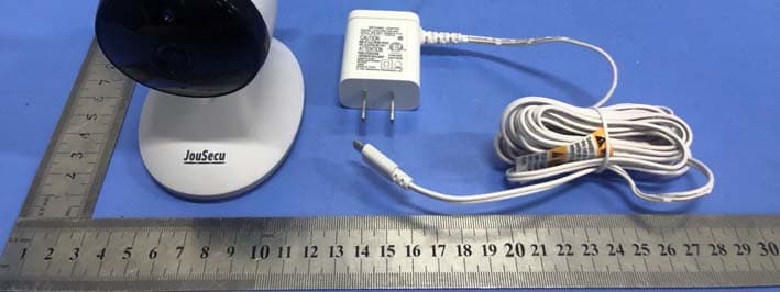
FCC ID: 2AV29-B255 TB-RF-075-1.0 Appendix III EUT External Photographs Photo 1 Appearance of EUT Photo 2 Appearance of EUT FCC ID: 2AV29-B255 TB-RF-075-1.0 Photo 3 Appearance of EUT Photo 4 Appearance of EUT FCC ID: 2AV29-B255 TB-RF-075-1.0 Photo 5 Appearance of EUT
ID Label/Location Info
FCC ID: 2AV29-B255 TB-RF-075-1.0 AppendixIFCC ID Label FCC ID: 2AV29-B255 TB-RF-075-1.0 Appendix II ID Label Location ID LOCATION
Internal Photos
FCC ID: 2AV29-B255 TB-RF-075-1.0 Appendix IV EUT Internal Photographs Photo 6 Internal of EUT Photo 7 Internal of EUT Antenna FCC ID: 2AV29-B255 TB-RF-075-1.0 Photo 8 Internal of EUT Photo 9 Appearance of PCB FCC ID: 2AV29-B255 TB-RF-075-1.0 Photo 10 Appearance of PCB Photo 11 Appearance of PCB FCC ID: 2AV29-B255 TB-RF-075-1.0 Photo 12 Appearance of PCB Photo 13 Appearance of PCB FCC ID: 2AV29-B255 TB-RF-075-1.0 Photo 14 Appearance of Adapter
RF Exposure Info
Shenzhen Toby Technology Co., Ltd. Report No.: TBR-C-202204-0149-14 Page: 1 of 3 TB-RF-075-1.0 Maximum Permissible Exposure Evaluation FCC ID: 2AV29-B255 1. Client Information Applicant : Zhongshan Jesmay Electronics Co., Ltd Address : No.1 Industry District, Tan Zhou Town, Zhong Shan City, Guangdong, China Manufacturer : Zhongshan Jesmay Electronics Co., Ltd Address : No.1 Industry District, Tan Zhou Town, Zhong Shan City, Guangdong, China 2. General Description of EUT EUT Name : Baby Monitor Models No. : JM55875T, B255 Model Different : All these models are the same PCB, layout and electrical circuit, The only difference is the Brand Name. Product Description : Operation Frequency: 2410MHz~2477MHz Number of Channel: 23 Channels Antenna Gain: 3dBi PIFA Antenna Power Rating : Adapter (Model: ZD5C050100USW) Input: AC 100-240V~50/60Hz, 0.2A Output: DC 5.0V,1A Software Version : N/A Hardware Version : N/A Connecting I/O Port(S) : : Please refer to the User's Manual Remark : the evaluation report used the EUT(202204-0149-3-2#). Report No.: TBR-C-202204-0149-14 Page: 2 of 3 TB-RF-075-1.0 MPE Calculations for WIFI 1. Antenna Gain: PIFA Antenna:3dBi. 2. EUT Operation Condition: Software provided by client enabled the EUT to transmit and receive data at lowest, middle and highest channel individually. 3. Exposure Evaluation: Equation from page 18 of OET Bulletin 65, Edition 97-01 S=(PG)/4πR 2 Where S: power density P: power input to the antenna G: power gain of the antenna in the direction of interest relative to an isotropic radiator. R: distance to the center of radiation of the antenna 4. Test Result: 2.4G WiFi Mode Conducted Power(max) (dBm) Turn-up Power (dB) Max tune up power (dBm) [P] ANT Gain (dBi) [G] Distance (cm) [R] Power Density (mW/ cm 2 ) [S] Limit of Power Density (mW/ cm 2 ) (S) 2.4G 7.991 7±1 8 3 20 0.00250 1 5. Conclusion: As specified in Table 1B of 47 CFR 1.1310- Limits for Maximum Permissible Exposure (MPE), Limits for General Population/ Uncontrolled Exposure Frequency Range (MHz) Power density (mW/ cm 2 ) 300-1,500 F/1500 1,500-100,000 1.0 For 2.4WIFI:2412~2462 MHz MPE limit S: 1mW/ cm 2 The MPE is calculated as 0.00250mW / cm 2 < limit 1mW / cm 2 . So, RF exposure limit warning or SAR test are not required. The EUT will only be used with a separation of 20cm or greater between the antenna and nearby persons and can therefore be considered a mobile transmitter per 47 CFR2.1091 Report No.: TBR-C-202204-0149-14 Page: 3 of 3 TB-RF-075-1.0 (b).The RF Exposure Information page from the manual is included here for reference. Note For a more detailed features description, please refer to the RF Test Report. 6. Conclusion: The measurement results comply with the FCC Limit per 47 CFR 2.1091 for the uncontrolled RF Exposure of mobile device. -----END OF REPORT-----
Test Report
Shenzhen Toby Technology Co., Ltd. Report No.: TBR-C-202204-0149-3 Page: 1 of 50 TB-RF-074-1.0 1 A/F., Building.6, Rundongsheng Industrial Zone, Longzhu, Xixiang, Bao’an, Shenzhen, Guangdong, China Tel: +86 75526509301 Fax: +86 75526509195 Radio Test Report FCC ID: 2AV29-B255 Report No. : TBR-C-202204-0149-3 Applicant : Zhongshan Jesmay Electronics Co., Ltd Equipment Under Test (EUT) EUT Name : Baby Monitor Model No. : JM55875T Series Model No. : B255 Brand Name : JouSecu, JouJou, JouLINK Sample ID : 202204-0149-3-1# 202204-0149-3-2# Receipt Date : 2022-05-16 Test Date : 2022-05-16 to 2022-06-01 Issue Date : 2022-06-06 Standards : FCC Part 15, Subpart C 15.247 Test Method : ANSI C63.10: 2013 Conclusions : PASS In the configuration tested, the EUT complied with the standards specified above, The EUT technically complies with the FCC requirements Test/Witness Engineer : Seven Wu Engineer Supervisor : Ivan Su Engineer Manager : Ray Lai This report details the results of the testing carried out on one sample. The results contained in this test report do not relate to other samples of the same product. The manufacturer should ensure that all products in series production are in conformity with the product sample detailed in the report. Report No.: TBR-C-202204-0149-3 Page: 2 of 50 TB-RF-074-1.0 Contents CONTENTS ............................................................................................................................................. 2 1. GENERAL INFORMATION ABOUT EUT ............................................................................. 5 1.1 Client Information ................................................................................................................. 5 1.2 General Description of EUT (Equipment Under Test) ................................................... 5 1.3 Block Diagram Showing the Configuration of System Tested ...................................... 6 1.4 Description of Support Units .............................................................................................. 7 1.5 Description of Test Mode .................................................................................................... 7 1.6 Description of Test Software Setting ................................................................................ 8 1.7 Measurement Uncertainty .................................................................................................. 8 1.8 Test Facility ........................................................................................................................... 9 2. TEST SUMMARY ..................................................................................................................... 10 3. TEST SOFTWARE ................................................................................................................... 10 4. TEST EQUIPMENT .................................................................................................................. 11 5.CONDUCTED EMISSION TEST .................................................................................................... 12 5.1 Test Standard and Limit .................................................................................................... 12 5.2 Test Setup ........................................................................................................................... 12 5.3 Test Procedure ................................................................................................................... 13 5.4 Deviation From Test Standard ......................................................................................... 13 5.5 EUT Operating Mode ........................................................................................................ 13 5.6 Test Data ............................................................................................................................. 13 5. RADIATED EMISSION TEST ................................................................................................ 14 6.1 Test Standard and Limit .................................................................................................... 14 6.2 Test Setup ........................................................................................................................... 15 6.3 Test Procedure ................................................................................................................... 16 6.4 Deviation From Test Standard ......................................................................................... 17 6.5 EUT Operating Condition ................................................................................................. 17 6.6 Test Data ............................................................................................................................. 17 6. RESTRICTED BANDS AND BAND-EDGE TEST ............................................................. 18 7.1 Test Standard and Limit .................................................................................................... 18 7.2 Test Setup ........................................................................................................................... 18 7.3 Test Procedure ................................................................................................................... 19 7.4 Deviation From Test Standard ......................................................................................... 20 7.5 EUT Operating Condition ................................................................................................. 20 7.6 Test Data ............................................................................................................................. 20 7. NUMBER OF HOPPING CHANNEL .................................................................................... 21 8.1 Test Standard and Limit ............................................................…
Text truncated - open the document above for the full version.
Test Setup Photos
FCC ID: 2AV29-B255 TB-RF-075-1.0 AppendixVEUT Test Photographs Photo of Setup for Radiated Emission (Below 1 GHz) Photo of Setup for Radiated Emission (Above 1 GHz) FCC ID: 2AV29-B255 TB-RF-075-1.0 Photo of Setup for Conducted Emission -----END OF REPORT-----
Contact Information
Applicant
cong chen(Engineer)
Test Firm
Shenzhen Toby Technology Co., Ltd.Ray Lai
Technical Specifications
| # | Rule Parts | Frequency Range | Power Output |
|---|---|---|---|
| 1 | 15C | 2.41 GHz - 2.48 GHz | 6.30 mW |
Other Applications from Zhongshan Jesmay Electronics Co.,Ltd
2AV29JM55993TR
Dec 28, 2020Baby Monitor
Equipment Class
DSS - Part 15 Spread Spectrum Transmitter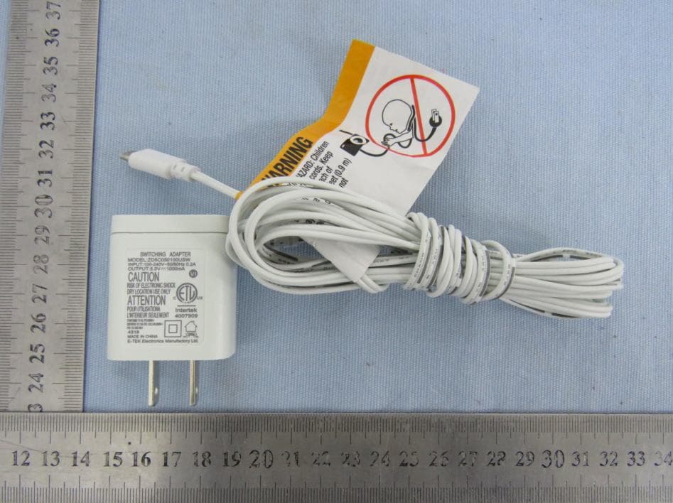
2AV29B036TR
Aug 16, 2020Video Baby Monitor-Camera
Equipment Class
DTS - Digital Transmission System
2AV29-56406
Jul 20, 2020NVR
Equipment Class
DTS - Digital Transmission System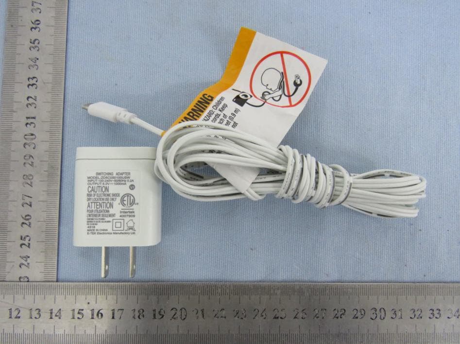
2AV29B024T
Apr 11, 2020Video Baby Monitor-Camera
Equipment Class
DTS - Digital Transmission System