2AV29B024TVideo Baby Monitor-Camera
Zhongshan Jesmay Electronics Co.,Ltd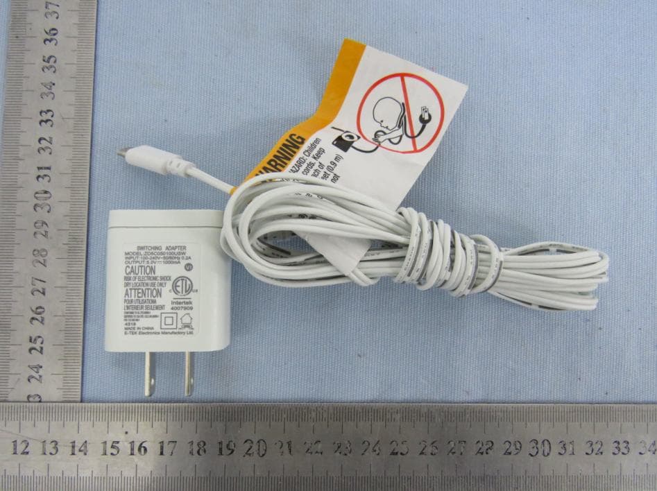
Click to zoom
Application Details
- Equipment Class
- DTS - Digital Transmission System
- Date of Grant
- Apr 11, 2020
- Application Purpose
- Original Equipment
- Date of Application
- Apr 11, 2020
- Equipment Note
- Video Baby Monitor-Camera
- Frequency Range
- 2406.00000000 - 2475.00000000
- Country
- China
Documents & Files
Document Text
Text extracted from the exhibit documents filed with the FCC. Open a document above to read the original.
Users Manual
WARNING STRANGULATION HAZARD Children have STRANGLED in cords. Keep this cord out of reach of children (more than 3 feet/1 meter away fr om the crib). Never use extension cords with AC adapters. Only use the AC Adapters pro vided. WARNING Adult assembly required. Keep small parts away from children when assembling. Warning Information Keep this instruc�on manual for future reference. For adult use only. WARNING When an AC Adapter is plugged into an electrical outlet, do not the exposed end. Test baby monitor before first use, periodically, and when changing loca�on of the baby unit(Camera). Do not use monitor near water (Such as bathtub, Sink, etc) Keep parent unit away from heat sources (Such as stoves, ra diators, etc) Make sure there is proper ven�la�on around baby unit and parent unit. This product is not a toy. Do not allow children to play with it. The mains plug or an appliance coupler is used as the disconnect device, the disconnect device shall re main readily operable. The baby monitor should not be considered as a medical device . While using the baby monitor, it is strongly recommended to have an adult directly checking on your baby. Premature babies or children considered at risk must be supervised by your pediatrician or other medical staff. THIS PRODUCT CANNOT REPLACE RESPONSIBLE ADULT SUPERVISION Use only the original rechargeable ba�ery provided. Do not shot-circuit supply terminals. Remove ba�ery when product is store d for long periods of �me or when ba�ery is exhausted. Dispose of exhausted ba�ery properly. Keep all ba�eries away from children. The apparatus shall not be exposed to dripping or splashing and that no objects filled with liquids, such as va ses, shall be placed on the apparatus. Danger of explosion if ba�ery is incorrectly replaced. Replace only with the same or equivalent type. Ba�eries (ba�ery pack or ba�eries installed) shall not be exposed to excessive heat such as sunshine, fire or t he like. Ba�ery Warning Precau�ons Do not overload wall outlets, extension cords, or integral conv enience receptacles as this ca n result in a risk of fire or electrics shock. The baby monitor works be�er in temperature ranging between 0 and 40 (32 a nd 104) Do not dismantle the appliance. It does not contain any parts that may be used independently. Never Expose the baby monitor for long period to sun’s direct rays and never place it next to a source of heat, in a damp or very dusty room. Never push objects of any kind into this product through openings as they may touch dangerous voltage points or short-out parts that could re sult in a fire or electric shock. Never spill liquid of any kind on the product. Do not a�empt to service this product yourself as opening or removing covers may expose you to dangerous voltage or other hazards. Refer all servicing to qualified service personnel. The product should be mounted to a wall or ceiling inly as recommended by the manufacturer. This device complies with Part 15 of the FCC Rules. Opera�on is subject to the following two condi�ons: (1) This device may not cause harmful interference, a nd (2) This device must accept any interference received, including interference that may cause undesired opera�on. FCC Cau�on To a ssure con�nued compliance, any changes or modifica�ons not expre ssly approved by the party responsible for compliance could void the user's authority to operate this equipment. (Example - use only shielded interface cables when connec�ng to computer or peripheral devices). Federal Communica�on Commission Interference Statement This equipment has been tested and found to comply with the limits for a Class B digital device, pursuant to P art 15 of the FCC Rul es. These limits are designed to provi de reasonable protec�on against harmful interference in a residen�al installa�on. This equipment generates, uses and can radiate radio frequency energy and, if not installed and used in accordance with the instruc�ons, may cause harmful interference to radio communica- o�ons. However, there is no guarantee that interference will not occur in a par�cular installa�on. If this equipment does cause harmful interference to radio or television recep�on, which can be determined by turning the equipment off and on, the user i s encouraged to try to corr ect the interference by one of the following measures: . Reorie nt or relocate the receiv ing antenna. . Increase the separa�on between the equipment and receiver. . Connect the equipment into an outlet on a circuit different from that to which the receiver is connected. . Consult the deal er or an experienced radio/TV technician for help. FCC Radia�on Exposure Statement This equipment complies with FCC RF radia�on exposure limits set forth for an uncontrolled environment. This equipment should be installed a nd operated with a minimum distance of 20 cen�meters between the radiator and your body. This transmi�er must not be co-located or opera�ng in conjunc�on with any oth er antenna or transmi�er. The antennas used for t his transmi�er must be installed to provi de a separa�on distance of at least 20 cm from all persons and must not be co-located or opera�ng in conjunc�on with any oth er antenna or transmi�er. JouSecu’s baby monitor warranty policy JouSecu will repair or r eplace (at our op�on) your unit free of charge for 12 mont hs from the date of purchase if the unit is defec�ve in work manship or materials. To claim your repair/replacement, the product must be returned to JouSecu together with a copy of the purchase receipt. In the absence of the purc hase receipt, the warranty will be 12 mont hs from the date of manufacture. This warranty does not apply to normal wear or damage from misuse, abuse, improper storage and handling, installa�on, accident, unauthorized repair or altera�on. Please contact our Customer service by Facebook JouSecu or via email for details. Industry Canada Statement This device complies with Industry Canada licenc e-ex empt RSS standard. Opera�on …
Text truncated - open the document above for the full version.
External Photos
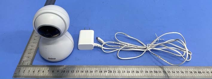
FCC ID: 2AV29B024T External photo FCC ID: 2AV29B024T FCC ID: 2AV29B024T FCC ID: 2AV29B024T FCC ID: 2AV29B024T FCC ID: 2AV29B024T
ID Label/Location Info
2AV29B024T Label & location
Operational Description
Zhongshan Jesmay Electronics Co., Ltd Declaration concerning Antenna Specification It is hereby declared that the product Model No.: B024T, B017T, JM55943T, JM55973T FCC ID: 2AV29B024T fulfills the requirement in FCC test relating to the antenna type. The device specified above confirms to the FCC recommendations for integral antenna type(s) described below: Model No. of antenna: 2.4G Antenna Type of antenna: permanently attached (Integral antenna) Gain of the antenna: 2 dBi Frequency range: 2406-2475 MHz The mounting of the antenna is fixed to the radio module and no other antenna should be used. Company name: Zhongshan Jesmay Electronics Co., Ltd Address: No.1 Industry District, Tan Zhou Town, City: Zhong Shan City, Guangdong, ZIP / Postal code: N/A Country: China Place: Cong chen Date: 2020-04-08 Signature:
RF Exposure Info
Dongguan Nore Testing Center Co., Ltd. Report No.: NTC2003019F-1 FCC ID: 2AV29B024T RF EXPOSURE EVALUATION EUT Specification EUT Video Baby Monitor-Camera Frequency band (Operating) WLAN: 2.412GHz ~ 2.462GHz WLAN: 5.18GHz ~ 5.24GHz WLAN: 5.745GHz ~ 5825GHz Others( 2.406GHz ~ 2.475GHz) Device category Portable (<20cm separation) Mobile (>20cm separation) Others ___ Antenna diversity Single antenna Multiple antennas Tx diversity Rx diversity Tx/Rx diversity Max. output power 17.350dBm(54.33mW) Antenna gain 2dBi Evaluation applied MPE Evaluation SAR Evaluation Limits for Maximum Permissible Exposure (MPE) Frequency Range(MHz) Electric Field Strength(V/m) Magnetic Field Strength(A/m) Power Density(mW/cm 2 ) 300-1500 -- -- F/1500 1500-100000 -- -- 1 Dongguan Nore Testing Center Co., Ltd. Report No.: NTC2003019F-1 FCC ID: 2AV29B024T Friis transmission formula: Pd=(Pout*G)\(4*pi*R 2 ) Where Pd= Power density in mW/cm 2 Pout=output power to antenna in Mw G= gain of antenna in linear scale Pi=3.1416 R= distance between observation point and center of the radiator in cm Pd the limit of MPE, 1mW/cm2. If we know the maximum gain of the antenna and total power input to the antenna, through the calculation, we will know the distance where the MPE limit is reached. Measurement Result Channel Gain Channel Frequency (MHz) Max Output power (dBm) Tolerance Max Tune-UP power (mW) Power density at 20cm (mW/ cm 2 ) Power density Limits (mW/cm 2 ) Low 2 2406 17.350 ± 0.5 60.95 0.019 1 Middle 2 2442 17.266 ± 0.5 59.79 0.019 1 High 2 2475 16.592 ± 0.5 51.19 0.016 1
Test Report
Dongguan Nore Testing Center Co., Ltd. Report No.: NTC2003019FV00 FCC ID: 2AV29B024T Page 2 of 34 Table of Contents 1. GENERAL INFORMATION ................................................................................................ 5 1.1 PRODUCT DESCRIPTION FOR EQUIPMENT UNDER TEST ................................................................. 5 1.2 RELATED SUBMITTAL(S) / GRANT (S) ............................................................................................ 7 1.3 TEST METHODOLOGY .................................................................................................................. 7 1.4 EQUIPMENT MODIFICATIONS ........................................................................................................ 7 1.5 SUPPORT DEVICE ....................................................................................................................... 7 1.6 TEST FACILITY AND LOCATION ..................................................................................................... 8 1.7 SUMMARY OF TEST RESULTS ....................................................................................................... 9 2. SYSTEM TEST CONFIGURATION .................................................................................. 10 2.1 EUT CONFIGURATION ............................................................................................................... 10 2.2 SPECIAL ACCESSORIES ............................................................................................................. 10 2.3 DESCRIPTION OF TEST MODES ................................................................................................... 10 2.4 EUT EXERCISE ......................................................................................................................... 10 3. CONDUCTED EMISSIONS TEST .................................................................................... 11 3.1 TEST SET-UP (BLOCK DIAGRAM OF CONFIGURATION) ................................................................ 11 3.2 TEST CONDITION ....................................................................................................................... 11 3.3 MEASUREMENT RESULTS .......................................................................................................... 11 4. MAX. CONDUCTED OUTPUT POWER ........................................................................... 14 4.1 MEASUREMENT PROCEDURE ..................................................................................................... 14 4.2 TEST SET-UP (BLOCK DIAGRAM OF CONFIGURATION) ................................................................ 14 4.3 MEASUREMENT RESULTS .......................................................................................................... 14 5. 6DB BANDWIDTH ............................................................................................................ 15 5.1 MEASUREMENT PROCEDURE ..................................................................................................... 15 5.2 TEST SET-UP (BLOCK DIAGRAM OF CONFIGURATION) ................................................................ 15 5.3 MEASUREMENT RESULTS .......................................................................................................... 15 6. POWER SPECTRAL DENSITY ........................................................................................ 18 6.1 MEASUREMENT PROCEDURE ..................................................................................................... 18 6.2 TEST SET-UP (BLOCK DIAGRAM OF CONFIGURATION) ................................................................ 18 6.3 MEASUREMENT RESULTS .......................................................................................................... 18 7. BAND EDGE AND CONDUCTED SPURIOUS EMISSIONS ........................................... 21 7.1 REQUIREMENT AND MEASUREMENT PROCEDURE ........................................................................ 21 7.2 TEST SET-UP (BLOCK DIAGRAM OF CONFIGURATION) ................................................................ 21 7.3 MEASUREMENT RESULTS .......................................................................................................... 21 Dongguan Nore Testing Center Co., Ltd. Report No.: NTC2003019FV00 FCC ID: 2AV29B024T Page 3 of 34 8. RADIATED SPURIOUS EMISSIONS AND RESTRICTED BANDS ................................. 26 8.1 TEST SET-UP (BLOCK DIAGRAM OF CONFIGURATION) ................................................................ 26 8.2 MEASUREMENT PROCEDURE ..................................................................................................... 27 8.3 LIMIT ........................................................................................................................................ 28 8.4 MEASUREMENT RESULTS ................................................................................................. 28 9. ANTENNA APPLICATION ............................................................................................... 33 9.1 ANTENNA REQUIREMENT............................................................................................................ 33 9.2 MEASUREMENT RESULTS .......................................................................................................... 33 10. TEST EQUIPMENT LIST ................................................................................................ 34 Dongguan Nore Testing Center Co., Ltd. Report No.: NTC2003019FV00 FCC ID: 2AV29B024T Page 4 of 34 Revision History of This Test Report Report Number Description Issued Date NTC2003019FV00 Initial Issue 2020-03-30 Dongguan Nore Testing Center Co., Ltd. Report No.: NTC2003019FV00 FCC ID: 2AV29B024T Page 5 of 34 1. GENERAL INFORMATION 1.1 Product Description for Equipment under Test E.U.T. : Video Baby Monitor-Camera Main model number : JM55943T Additional Model num…
Text truncated - open the document above for the full version.
Test Setup Photos
FCC ID: 2AV29B024T Test photo Radiated emission Below 30MHz 30MHz-1GHz FCC ID: 2AV29B024T Above 1GHz Conducted emission
Contact Information
Applicant
cong chen(Engineer)
Test Firm
Dongguan NTC CO., Ltd.Jees Hong
[email protected]+86-769-22022444
Technical Specifications
| # | Rule Parts | Frequency Range | Power Output |
|---|---|---|---|
| 1 | 15C | 2.41 GHz - 2.48 GHz | 55.00 mW |
Other Applications from Zhongshan Jesmay Electronics Co.,Ltd
2AV29-B255
Jun 10, 2022Baby Monitor
Equipment Class
DSS - Part 15 Spread Spectrum Transmitter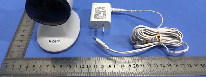
2AV29JM55993TR
Dec 28, 2020Baby Monitor
Equipment Class
DSS - Part 15 Spread Spectrum Transmitter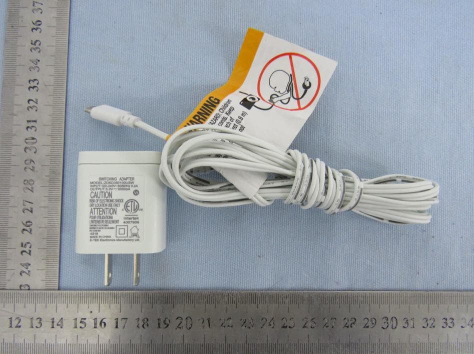
2AV29B036TR
Aug 16, 2020Video Baby Monitor-Camera
Equipment Class
DTS - Digital Transmission System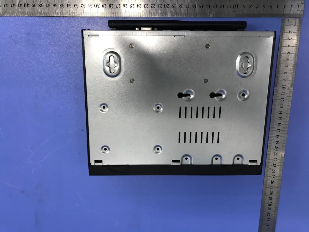
2AV29-56406
Jul 20, 2020NVR
Equipment Class
DTS - Digital Transmission System