2AVD2-MH21904Truly wireless earphone
Shenzhen Monster Creative Technology Co., Ltd.
Click to zoom
Application Details
- Equipment Class
- DTS - Digital Transmission System
- Date of Grant
- Jul 09, 2020
- Application Purpose
- Original Equipment
- Date of Application
- Jul 08, 2020
- Equipment Note
- Truly wireless earphone
- Frequency Range
- 2402.00000000 - 2480.00000000
- Country
- China
Documents & Files
Document Text
Text extracted from the exhibit documents filed with the FCC. Open a document above to read the original.
Users Manual
Model No.:MH21904 FCC ID:2AVD2-MH21904 Quick Start Guide Please read this Quick Start Guide carefully and keep it for future use. Product Overview In-ear Earphone x 2 (left & right) Charging Case USB-C Charging Cable Quick Start Guide and Warranty Letter 1. Microphones 2. Multi Function Button(MFB)& Indicator Light 3. Optical Sensor 4. Charging Contacts 5. Charging Case Indicator Light 6. USB-C Charging Port 7. Wireless Charging Area Power On/Off Open the charging case, take out the earphones, it will automatically turn on. To turn off the earphones, put back to the charging case and close. Earphones will be turned off and start charging. Wired/Wireless Charging Case Charging Besides using the included USB-C charging cable to charge the charging case, the charging case can be charged by compatible wireless charging device. After charging case is fully charged, charging case indicator light will remain on for around 5 minutes then turn off. Pairing Open the charging case, take out the earphones, it will automatically turn on. left and right earphones will be connected automatically within few seconds. Then “pairing” voice prompt will be heard. For new device connection, go to the Bluetooth settings on your mobile device and set it to search for new devices (new Monster device). Once the earphones are paired to the designated device, you will hear “connected”. Volume Control Volume down: quickly double press the MFB on the left earphone during music streaming. Volume up: quickly double press the MFB on the right earphone during music streaming. Calling Answer / End a call: Click the MFB touch button. Reject the call: Press and hold the MFB touch button for about 2 seconds. Music Play/Pause music: • short press the MFB button. • built-in optical senso r, smart in-ear detection. o pauses the music when earphone is taken off. o plays the music when earphone is put on. Previous song: Press and hold the MFB button on the left earphone for about 2 seconds. Next song: Press and hold the MFB button on the right earphone for about 2 seconds. Voice Control After connecting to the phone, quickly double press the MFB to activate the voice assistant. LED Indicator Guide Mode Description Voice prompts Power On White LED indicator light stays on about 1 second “Power On” Power Off Red LED indicator light stays on about 1 second “Power Off ” Pairing White LED indicator light flashes quickly “Pairing” Connected Indicator light goes off “Connected” Earphone charging Red LED indicator light stays on - Charging case Charging case indicator light flashes while charging. When charging case indicator light is off, it is fully charged. - Note: * After removing the headset from the charging box, without pressing any buttons, the left and right headsets will automatically connect and enter pairing mode automatically. * Please put the earphone in the correct position to charge. * If the battery is not replaced properly, there is a danger of explosion. The battery can only be replaced with batteries of the same type or equivalent. It is not recommended to replace the battery without permission, but it can be returned to the manufacturer for replacement. * Battery [battery pack or battery combination] must not be exposed to lighting, baking or similar overheating environment. FCC Statement Changes or modifications not expressly approved by the party responsible for compliance could void the user's authority to operate the equipment. This equipment has been tested and found to comply with the limits for a Class B digital device, pursuant to Part 15 of the FCC Rules. These limits are designed to provide reasonable protection against harmful interference in a residential installation. This equipment generates uses and can radiate radio frequency energy and, if not installed and used in accordance with the instructions, may cause harmful interference to radio communications. However, there is no guarantee that interference will not occur in a particular installation. If this equipment does cause harmful interference to radio or television reception, which can be determined by turning the equipment off and on, the user is encouraged to try to correct the interference by one or more of the following measures: • Reorient or relocate the receiving antenna. • Increase the separation between the equipment and receiver. • Connect the equipment into an outlet on a circuit different from that to which the receiver is connected. • Consult the dealer or an experienced radio/TV technician for help This device complies with part 15 of the FCC rules. Operation is subject to the following two conditions (1) this device may not cause harmful interference, and (2) this device must accept any interference received, including interference that may cause undesired operation. RF warning statement: The device has been evaluated to meet general RF exposure requirement. The device can be used in portable exposure condition without restriction.
Attestation Statements
Declaration I am the signer Qingyun He The device has left and right earphone, The left and right earphones are electrically identical. Item Name :Truly wireless earphone Model Number:MH21904 FCC ID:2AVD2-MH21904 <Signature> Name: Qingyun He Title: R&D Manager Company: Shenzhen Monster Creative Technology Co., Ltd.
External Photos
External Photos M/N: MH21904 External Photos M/N: MH21904 External Photos M/N: MH21904 External Photos M/N: MH21904 External Photos M/N: MH21904 External Photos M/N: MH21904 External Photos M/N: MH21904 External Photos M/N: MH21904 External Photos M/N: MH21904 External Photos M/N: MH21904 External Photos M/N: MH21904 External Photos M/N: MH21904 External Photos M/N: MH21904
Internal Photos
Internal Photos M/N: MH21904 Internal Photos M/N: MH21904 Internal Photos M/N: MH21904 Internal Photos M/N: MH21904 Internal Photos M/N: MH21904
RF Exposure Info
FCC ID: 2AVD2-MH21904 EST Technology Co., Ltd Report No. ESTE-R2006016 Page 1 of 3 FCC RF EXPOSURE REPORT Shenzhen Monster Creative Technology Co., Ltd. Truly wireless earphone Model Number: MH21904 FCC ID: 2AVD2-MH21904 Prepared for: Shenzhen Monster Creative Technology Co., Ltd. No. 303, Building 1, Hezhou Jinfo Industrial Zone, Hezhou Village, Hangcheng Street, Baoan District,Shenzhen, Guangdong, China Prepared By: EST Technology Co., Ltd. Chilingxiang, Qishantou, Santun, Houjie, Dongguan, Guangdong, China Tel: 86-769-83081888-808 Report Number: ESTE-R2006016 Date of Test: May. 25~Jun. 03, 2020, 2020 Date of Report: Jun. 04, 2020 FCC ID: 2AVD2-MH21904 EST Technology Co., Ltd Report No. ESTE-R2006016 Page 2 of 3 1. Applicable Standards FCC Part 2(Section 2.1093) FCC KD B447498 D01 General RF Exposure Guidance v06 2. Exposure Evaluation of Portable or Mobile Devices Human exposure to RF emissions from portable devices (47 CFR §2.1093), as defined by the FCC, must be evaluated with respect to the FCC-adopted limits for SAR. Evaluation of mobile devices, as defined by the FCC, may also be performed with respect to SAR limits, but in such cases it is usually simpler and more cost-effective to evaluate compliance with respect to field strength or power density limits. For certain devices that are designed to be used in both mobile and portable configurations similar to those described in 47 CFR §2.1091(d)(4), such as certain desktop phones and wireless modem modules, compliance for mobile configurations is also satisfied when the same device is evaluated for SAR compliance in portable configurations. SAR Test Exclusion Thresholds for 100 MHz – 6 GHz and ≤ 50 mm The 1-g and 10-g SAR test exclusion thresholds for 100 MHz to 6 GHz at test separation distances ≤ 50 mm are determined by [(max. power of channel, including tune-up tolerance, mW)/(min. test separation distance, mm)] · [√f(GHz)] ≤3.0 for 1-g SAR and ≤ 7.5 for 10-g extremity SAR where • f(GHz) is the RF channel transmit frequency in GHz • Power and distance are rounded to the nearest mW and mm before calculation • The result is rounded to one decimal place for comparison The test exclusions are applicable only when the minimum test separation distance is ≤ 50 mm and for transmission frequencies between 100 MHz and 6 GHz. When the minimum test separation distance is < 5 mm, a distance of 5 mm is applied to determine SAR test exclusion. FCC ID: 2AVD2-MH21904 EST Technology Co., Ltd Report No. ESTE-R2006016 Page 3 of 3 3. Evaluation Results Mode Frequency (MHz) Peak output Power (dBm) Peak output Power (mW) Target power (dBm) Results GFSK 2402 3.93 2.4717 3±1 0.779 2441 3.55 2.2646 3±1 0.785 2480 3.60 2.2909 3±1 0.791 8-DPSK 2402 5.42 3.4834 5±1 1.234 2441 4.96 3.1333 4±1 0.988 2480 5.10 3.2359 5±1 1.254 BLE (1M) 2402 4.22 2.6424 4±1 0.980 2440 3.67 2.3281 3±1 0.785 2480 3.81 2.4044 3±1 0.791 BLE (2M) 2402 4.58 2.8708 4±1 0.980 2440 4.02 2.5235 4±1 0.988 2480 4.12 2.5823 4±1 0.996 Note: 1. [(max. power of channel, including tune-up tolerance, mW)/(min. test separation distance, mm)] * [√f(GHz)] < 3.0. 2. SAR Test Exclusion Thresholds is 3.0 for separation distance 5mm. Therefore, SAR test is not required. End of Test Report
Test Report
FCC ID: 2AVD2-MH21904 EST Technology Co., Ltd Report No.ESTE-R2006015 Page 1 of 75 FCC PART 15C TEST REPORT FOR CERTIFICATION On Behalf of Shenzhen Monster Creative Technology Co., Ltd. Truly wireless earphone Model Number: MH21904 FCC ID: 2AVD2-MH21904 Prepared for: Shenzhen Monster Creative Technology Co., Ltd. No. 303, Building 1, Hezhou Jinfo Industrial Zone, Hezhou Village, Hangcheng Street, Baoan District,Shenzhen, Guangdong, China Prepared By: EST Technology Co., Ltd. Chilingxiang, Qishantou, Santun, Houjie, Dongguan, Guangdong, China Tel: 86-769-83081888-808 Report Number: ESTE-R2006015 Date of Test: May. 25~Jun. 03, 2020, 2020 Date of Report: Jun. 04, 2020 FCC ID: 2AVD2-MH21904 EST Technology Co., Ltd Report No.ESTE-R2006015 Page 2 of 75 TABLE OF CONTENTS Description Page TEST REPORT VERIFICATION ........................................................................................................................ 3 1. GENERAL INFORMATION ................................................................................................................. 5 1.1. Description of Device (EUT) ........................................................................................................... 5 1.2. Antenna Information ........................................................................................................................ 5 2. SUMMARY OF TEST ......................................................................................................................... 6 2.1. Summary of test result ...................................................................................................................... 6 2.2. Test Facilities .................................................................................................................................... 7 2.3. Measurement uncertainty ................................................................................................................. 8 2.4. Assistant equipment used for test ..................................................................................................... 8 2.5. Block Diagram .................................................................................................................................. 8 2.6. Test Mode ......................................................................................................................................... 9 2.7. Power Setting of Test Software ........................................................................................................ 9 2.8. Duty Cycle ...................................................................................................................................... 10 2.9. Channel List .................................................................................................................................... 12 2.10. Test Equipment List ....................................................................................................................... 13 3. 6DB BANDWIDTH ......................................................................................................................... 14 3.1. Limit ............................................................................................................................................... 14 3.2. Test Setup ....................................................................................................................................... 14 3.3. Spectrum Analyzer Setting ............................................................................................................. 14 3.4. Test Procedure ................................................................................................................................ 14 3.5. Test Result ...................................................................................................................................... 15 4. MAXIMUM PEAK OUTPUT POWER ................................................................................................ 19 4.1. Limit ............................................................................................................................................... 19 4.2. Test Setup ....................................................................................................................................... 19 4.3. Spectrum Analyzer Setting ............................................................................................................. 19 4.4. Test Procedure ................................................................................................................................ 19 4.5. Test Result ...................................................................................................................................... 20 5. POWER SPECTRAL DENSITY .......................................................................................................... 24 5.1. Limit ............................................................................................................................................... 24 5.2. Test Setup ....................................................................................................................................... 24 5.3. Spectrum Analyzer Setting ............................................................................................................. 24 5.4. Test Procedure ................................................................................................................................ 24 5.5. Test Result ...................................................................................................................................... 25 6. CONDUCTED BAND EDGE ............................................................................................................. 29 6.1. Limit .............................................................................................................................................…
Text truncated - open the document above for the full version.
Test Setup Photos
Conducted Test Radiated Test (Below 1GHz) Radiated Test (Above 1GHz)
Contact Information
Applicant
run long wang(R & D Manager)
Test Firm
EST Technology Co., Ltd.Iceman Hu
[email protected]+86 0769-83081888
Technical Specifications
| # | Rule Parts | Frequency Range | Power Output |
|---|---|---|---|
| 1 | 15C | 2.40 GHz - 2.48 GHz | 2.87 mW |
Other Applications from Shenzhen Monster Creative Technology Co., Ltd.
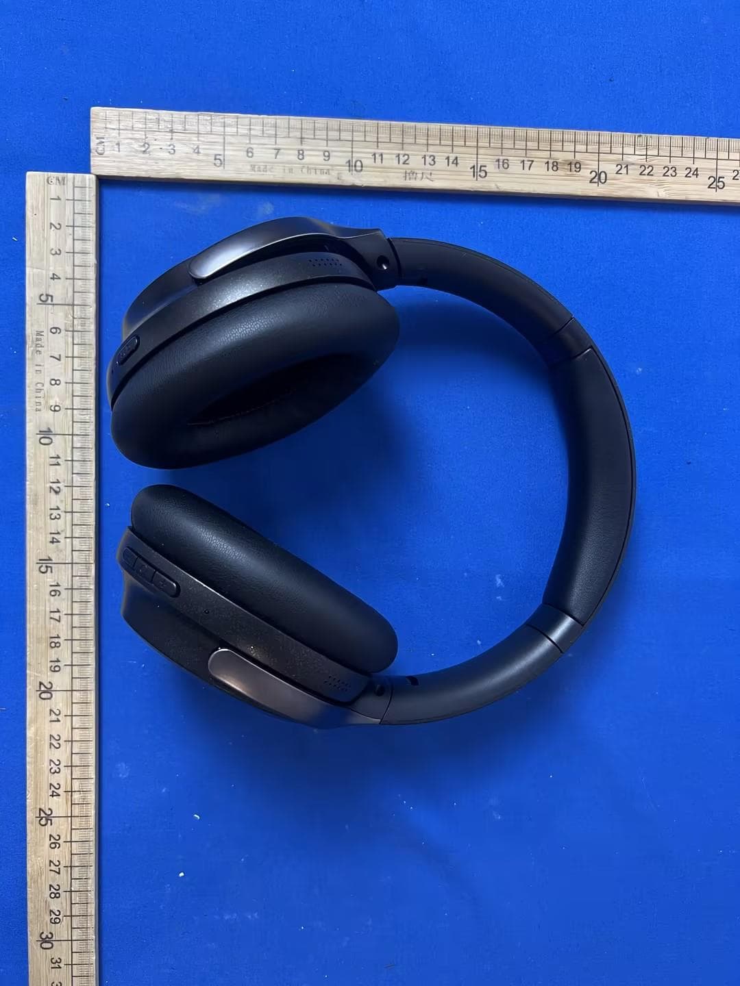
2AVD2-H32
Jun 30, 2026PORTABLE BLUETOOTH SPEAKER
Equipment Class
DSS - Part 15 Spread Spectrum Transmitter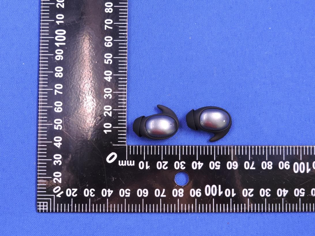
2AVD2-MH22280
Dec 19, 2025BLUETOOTH HEADPHONE
Equipment Class
DSS - Part 15 Spread Spectrum Transmitter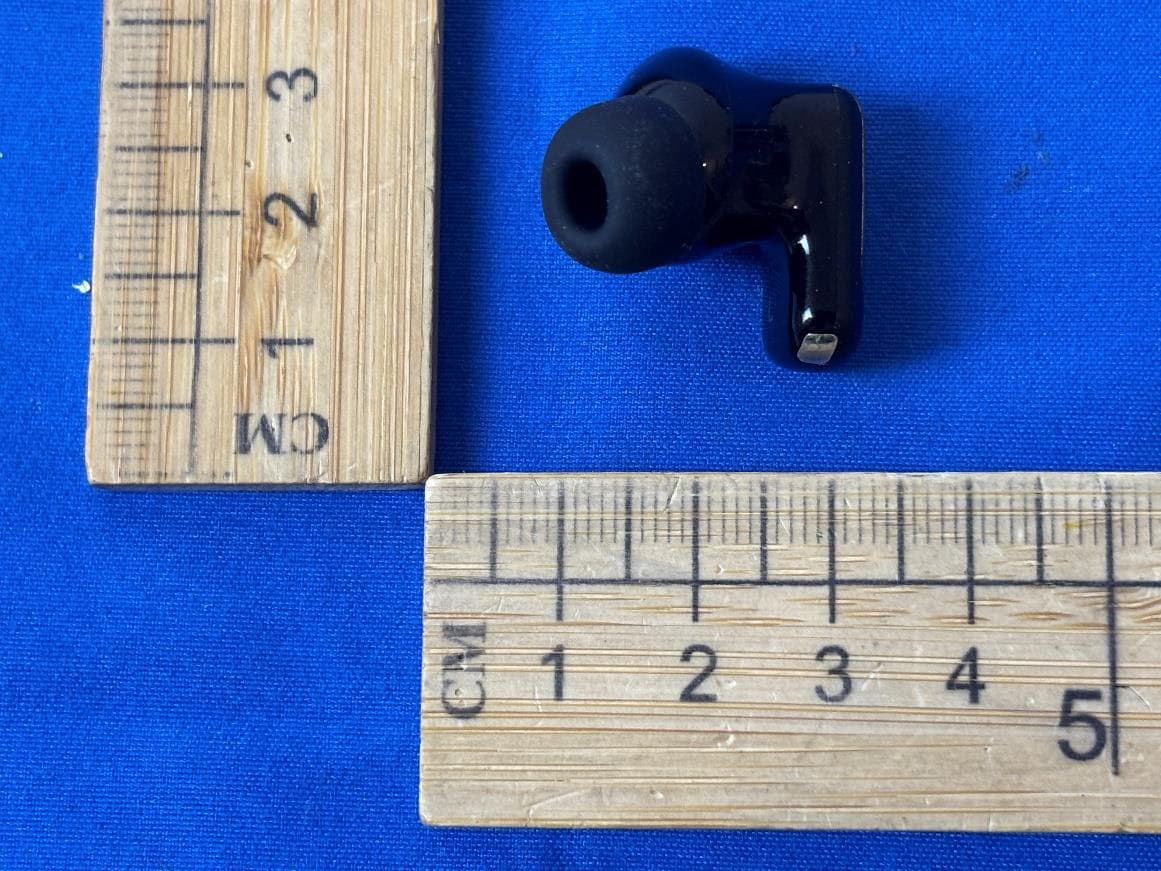
2AVD2-W55
Dec 17, 2025BLUETOOTH HEADPHONE
Equipment Class
DSS - Part 15 Spread Spectrum Transmitter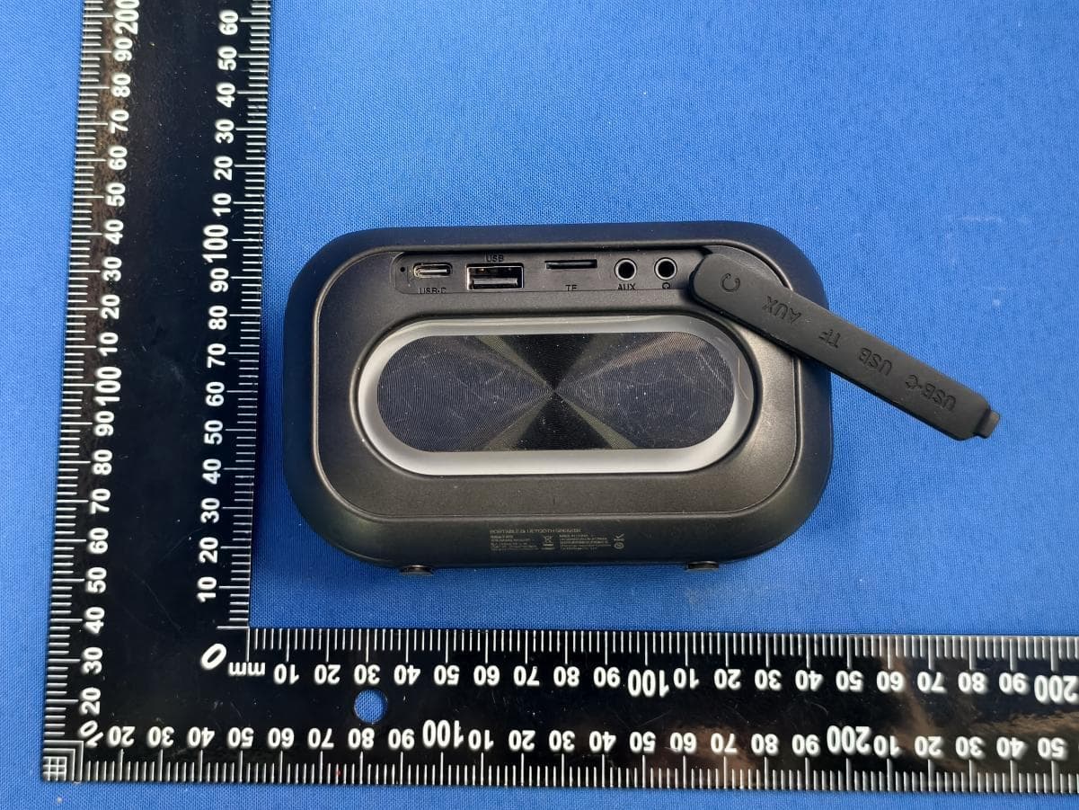
2AVD2-MS62110
Dec 16, 2025PORTABLE BLUETOOTH SPEAKER
Equipment Class
DSS - Part 15 Spread Spectrum Transmitter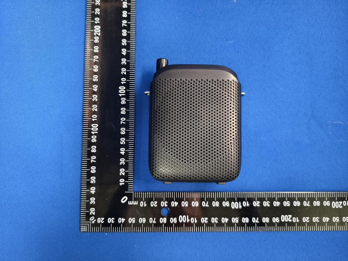
2AVD2-MS62144
Dec 12, 2025PORTABLE VOICE AMPLIFIER
Equipment Class
DSS - Part 15 Spread Spectrum Transmitter