2AVD2-MH31902Monster Bluetooth Headphones
Shenzhen Monster Creative Technology Co., Ltd.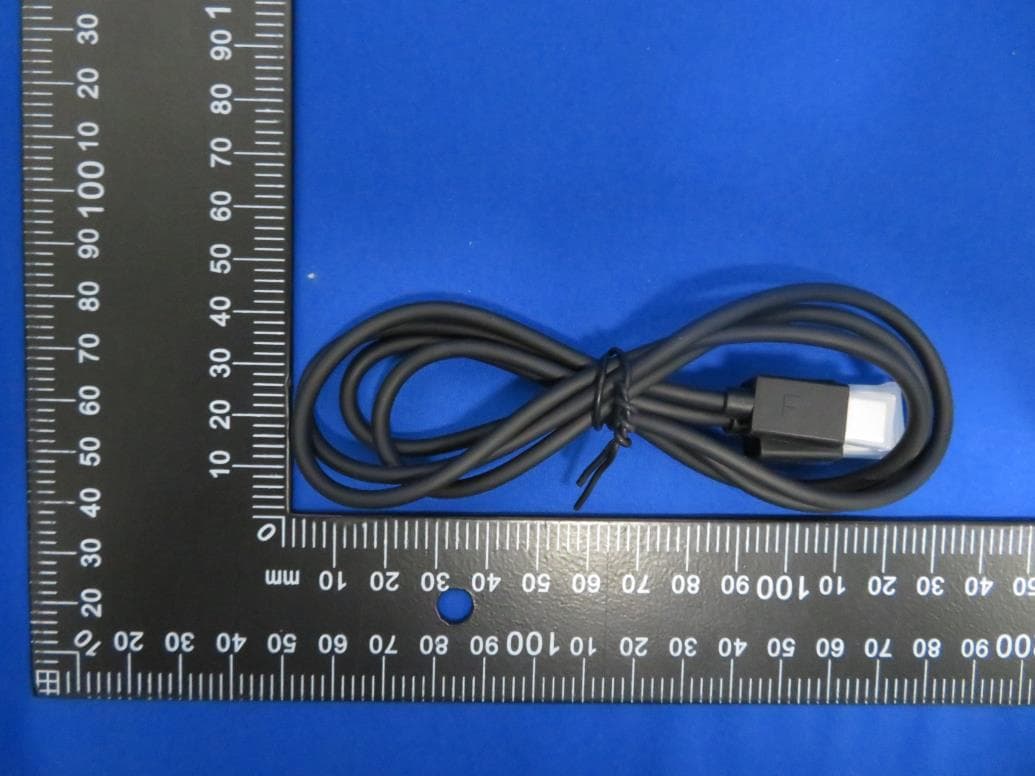
Click to zoom
Application Details
- Equipment Class
- DSS - Part 15 Spread Spectrum Transmitter
- Date of Grant
- Jul 20, 2020
- Application Purpose
- Original Equipment
- Date of Application
- Jul 20, 2020
- Equipment Note
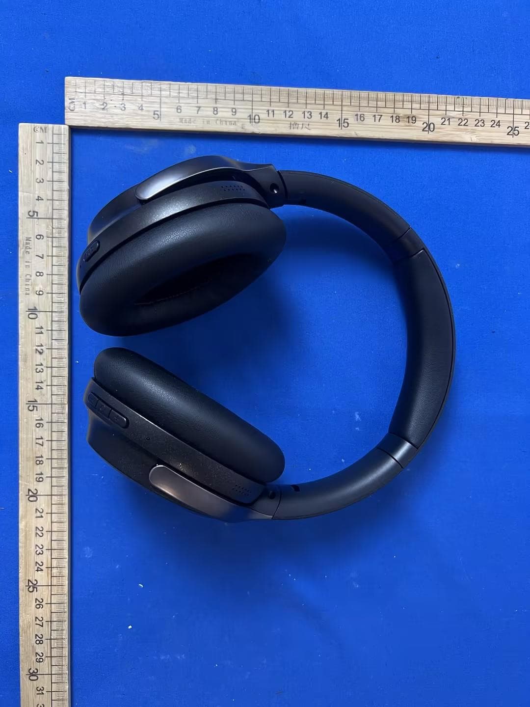
- Monster Bluetooth Headphones
- Frequency Range
- 2402.00000000 - 2480.00000000
- Country
- China
Documents & Files
Document Text
Text extracted from the exhibit documents filed with the FCC. Open a document above to read the original.
Users Manual
MONSTER PERSONA Model No.: MH31902 Quick Start Guide Please read this Quick Start Guide carefully and keep it for future use. Product Overview • Headphones • Audio Cable • Charging Cable • Quick Start Guide & Warranty letter • Carry Pouch 1. Volume Up Button, Track Forward 2. Volume Down Button, Track Back 3. Multi Function Button (MFB) (Power On/Play/Pause...) 4. Bluetooth white indication light 5. AUX interface 6. ANC green indication light 7. Active Noise Cancellation (ANC) Button Power On/Off In power off mode, press and hold the MFB for about 2 seconds to power on the headphones, the white indicator on for 1 second and you will hear “Power on”. In power on mode, press and hold the MFB for about 5 seconds to power off the headphones, the white indicator on for 1 second and you will hear “Power off”. ① ② ③ ④ ⑤ ⑥ ⑦ Pairing In power off mode, press and hold the MFB for about 5 seconds until indicator light flashes white, you hear “Power on”...”Pairing”. Now headphones are in pairing mode. Activate Bluetooth ® on your equipment and set it to search for new devices (new Monster device). When the headphones are paired successfully, “Paired. Your device is connected” will be heard. Note: When you unbox the headphones and power it on for the first time, it will enter to pairing mode automatically. Volume Control Short press the Volume Up or Down Button to turn volume up or down, you hear tone once you reach the maximum volume or minimum volume. Call Answer/End Call: short press the MFB Reject Call: long press the MFB about 2 seconds Redial: quickly double press the MFB for redial the last dialed phone number Music Play/Pause: In the music playback mode, press the MFB to play/pause music. Track back: In the music playback mode, press and hold the Volume Down Button for 2 seconds for previous song. Track forward: In the music playback mode, press and hold the Volume Up Button for 2 seconds for next song. Active Noise Cancellation (ANC) Turn on ANC function: When ANC is off, short press ANC button to activate the active noise cancellation function. When ANC is on, indicator stays green,You will hear the "ANC ON". Turn off ANC function: When ANC is on, short press ANC button to deactivate the active noise cancellation function,You will hear the "ANC OFF". Reset Paired Device List After power on, no Bluetooth device is connected, press and hold the MFB and Volume Up Button simultaneously for about 5 seconds. LED Guide to Indicator Lights Mode Description Indication Power On White LED indicator lights for about 1 second “Power On” Power Off White LED indicator lights for about 1 second “Power Off” Pairing White LED flashes quickly “Pairing” Connected No function operation, the indicator light is off “Paired, Your device is connected” ANC On Green light is on “ANC ON” ANC Off The green indicator is off “ANC OFF” Listen Responsibly To avoid hearing damage, make sure that the volume on your music player is turned down before connecting your headphones. After placing headphones in/on your ears, gradually turn up the volume until you reach a comfortable listening level. Noise levels are measured in decibels (dB), exposure to any noise at or above 85 dB can cause gradual hearing loss. Monitor your use; hearing loss is a function of loudness versus time. The louder it is, the less time you can be exposed to it. The softer it is, the more time you can listen to it. Get the most out of your equipment and enjoy great audio performance even at safe levels. Our headphones will allow you to hear more details at lower volume levels than ever before. Learn how to establish a safe listening level and review other important safety guidelines from the Consumer Electronics Association at www.ce.org. Important information on how to prevent Noise-Induced Hearing Loss (NIHL) and a comprehensive list of which noises can cause damage can be found on the Deafness Research Foundation’s website, www.drf.org. FCC Statement Changes or modifications not expressly approved by the party responsible for compliance could void the user's authority to operate the equipment. This equipment has been tested and found to comply with the limits for a Class B digital device, pursuant to Part 15 of the FCC Rules. These limits are designed to provide reasonable protection against harmful interference in a residential installation. This equipment generates uses and can radiate radio frequency energy and, if not installed and used in accordance with the instructions, may cause harmful interference to radio communications. However, there is no guarantee that interference will not occur in a particular installation. If this equipment does cause harmful interference to radio or television reception, which can be determined by turning the equipment off and on, the user is encouraged to try to correct the interference by one or more of the following measures: • Reorient or relocate the receiving antenna. • Increase the separation between the equipment and receiver. • Connect the equipment into an outlet on a circuit different from that to which the receiver is connected. • Consult the dealer or an experienced radio/TV technician for help This device complies with part 15 of the FCC rules. Operation is subject to the following two conditions (1) this device may not cause harmful interference, and (2) this device must accept any interference received, including interference that may cause undesired operation.
Cover Letter(s)
ShenzhenMonsterCreativeTechnologyCo.,Ltd. No.303,Building1,HezhouJinfoIndustrialZone,HezhouVillage,Baoan,Shenzhen,Guangdong,China DeclarationofAuthorization We Name:ShenzhenMonsterCreativeTechnologyCo.,Ltd. Address:No.303,Building1,HezhouJinfoIndustrialZone,HezhouVillage,Baoan,Shenzhen, Guangdong,China Declarethat: NameRepresentativeofagent:MarlinChen AgentCompanyname:MRTTechnology(Suzhou)Co.,Ltd Address:D8Building,YouxinIndustrialPark,No.2Tian'edangRd., WuzhongEconomicDevelopmentZone, City:Suzhou CountryChina isauthorizedtoapplyforCertificationofthefollowingproduct(s): ProductDescription:MonsterBluetoothHeadphones FCCID:2AVD2-MH31902 ModelNumber:MH31902 BrandName:MONSTER Sincerely, Signature: Name:QingyunHe Position:R&DManager ShenzhenMonsterCreativeTechnologyCo.,Ltd. Date:July12,2020
Cover Letter(s)
ShenzhenMonsterCreativeTechnologyCo.,Ltd. No.303,Building1,HezhouJinfoIndustrialZone,HezhouVillage,Baoan,Shenzhen,Guangdong,China ConfidentialityRequestLetter Date:July12,2020 FederalCommunicationsCommission AuthorizationandEvaluationDivision FCCID:2AVD2-MH31902 ConfidentialityRequest PursuanttoSections0.457and0.459oftheCommission’sRules,weherebyrequestconfidential treatmentofinformationaccompanyingthisapplicationasoutlinedbelow: 1.BlockDiagram 2.Schematics 3.OperationalDescription Theabovematerialscontaintradesecretsandproprietaryinformationnotcustomarilyreleased tothepublic.Thepublicdisclosureofthesemattersmightbeharmfultotheapplicantand provideunjustifiedbenefitstoitscompetitors. TheapplicantunderstandsthatpursuanttoRule0.457,disclosureofthisapplicationandall accompanyingdocumentationwillnotbemadebeforethedateoftheGrantforthisapplication. Sincerely, Signature: Name:QingyunHe Position:R&DManager ShenzhenMonsterCreativeTechnologyCo.,Ltd.
External Photos
Report No.: 2006RSU045-UE 1 of 5 EUT External Photograph (1) EUT Photo (2) EUT Photo Report No.: 2006RSU045-UE 2 of 5 (3) EUT Photo (4) EUT Photo Report No.: 2006RSU045-UE 3 of 5 (5) EUT Photo (6) EUT Photo Report No.: 2006RSU045-UE 4 of 5 (7) EUT Photo (8) EUT Photo Report No.: 2006RSU045-UE 5 of 5 (9) EUT Photo
ID Label/Location Info
深圳市魔声创新技术有限公司 CMTTI IDXXXXXXX 深圳市魔声创新技术有限公司CMTTI ID XXXXXXX 19.5mm 3.7mm
Internal Photos
Report No.: 2006RSU045-UE 1 of 8 EUT Internal Photograph (1) EUT Photo (2) EUT Photo Report No.: 2006RSU045-UE 2 of 8 (3) EUT Photo (4) EUT Photo Report No.: 2006RSU045-UE 3 of 8 (5) EUT Photo (6) EUT Photo Report No.: 2006RSU045-UE 4 of 8 (7) EUT Photo (FPC Antenna) (8) EUT Photo Report No.: 2006RSU045-UE 5 of 8 (9) EUT Photo (10) EUT Photo Report No.: 2006RSU045-UE 6 of 8 (11) EUT Photo (12) EUT Photo Report No.: 2006RSU045-UE 7 of 8 (13) EUT Photo (14) EUT Photo Report No.: 2006RSU045-UE 8 of 8 (15) EUT Photo
RF Exposure Info
MRT Technology (Suzhou) Co., Ltd Report No.: 2006RSU045-U2 Phone: +86-512-66308358 Report Version: V01 Web: www.mrt-cert.com Issue Date: 07-17-2020 Page Number: 1 of 7 RF Exposure Evaluation Declaration FCC ID: 2AVD2-MH31902 APPLICANT: Shenzhen Monster Creative Technology Co., Ltd. Application Type: Certification Product: Monster Bluetooth Headphones Model No.: MH31902 Brand Name: MONSTER FCC Classification: FCC Part 15 Spread Spectrum Transmitter (DSS) Test Procedure(s): KDB 447498 D01v06 Reviewed By: ( Jame Yuan ) Approved By: ( Robin Wu ) The test results relate only to the samples tested. The test results shown in the test report are traceable to the national/international standards through the calibration of the equipment and evaluated measurement uncertainty herein. The test report shall not be reproduced except in full without the written approval of MRT Technology (Suzhou) Co., Ltd. Report No.: 2006RSU045-U2 Page Number: 2 of 7 Revision History Report No. Version Description Issue Date Note 2006RSU045-U2 Rev. 01 Initial Report 07-17-2020 Valid Report No.: 2006RSU045-U2 Page Number: 3 of 7 1. PRODUCT INFORMATION 1.1. Equipment Description 1.2. Product Specification Subjective Product Name: Monster Bluetooth Headphones Model No.: MH31902 Brand Name: MONSTER Bluetooth Version: V5.0 (Single mode for BR/EDR) Power Supply: By Internal Battery or DC Adapter Operating Frequency: 2402~2480MHz Channel Number: 79 Type of modulation: GFSK, Pi/4 DQPSK, 8DPSK Data Rate: 1Mbps(GFSK), 2Mbps(Pi/4 DQPSK), 3Mbps (8DPSK) Antenna Type: FPC Antenna Antenna Gain: 2.95dBi Report No.: 2006RSU045-U2 Page Number: 4 of 7 2. RF Exposure Evaluation 2.1. Limits SAR Test Exclusion Thresholds for 100 MHz – 6 GHz and ≤ 50 mm Approximate SAR Test Exclusion Power Thresholds at Selected Frequencies and Test Separation Distances are illustrated in the following Table. The equation and threshold in Note 1 must be applied to determine SAR test exclusion. MHz 5 10 15 20 25 mm 150 39 77 116 155 194 SAR Test Exclusion Threshold (mW) 300 27 55 82 110 137 450 22 45 67 89 112 835 16 33 49 66 82 900 16 32 47 63 79 1500 12 24 37 49 61 1900 11 22 33 44 54 2450 10 19 29 38 48 3600 8 16 24 32 40 5200 7 13 20 26 33 5400 6 13 19 26 32 5800 6 12 19 25 31 MHz 30 35 40 45 50 mm 150 232 271 310 349 387 SAR Test Exclusion Threshold (mW) 300 164 192 219 246 274 450 134 157 179 201 224 835 98 115 131 148 164 900 95 111 126 142 158 1500 73 86 98 110 122 1900 65 76 87 98 109 2450 57 67 77 86 96 3600 47 55 63 71 79 5200 39 46 53 59 66 5400 39 45 52 58 65 5800 37 44 50 56 62 Note: The 1-g and 10-g SAR test exclusion thresholds for 100 MHz to 6 GHz at test separation distances ≤ 50 mm are determined by: Report No.: 2006RSU045-U2 Page Number: 5 of 7 [(max. power of channel, including tune-up tolerance, mW)/(min. test separation distance, mm)] * [√f(GHz)] ≤ 3.0 for 1-g SAR and ≤ 7.5 for 10-g extremity SAR, where ⚫ f(GHz) is the RF channel transmit frequency in GHz ⚫ Power and distance are rounded to the nearest mW and mm before calculation ⚫ The result is rounded to one decimal place for comparison ⚫ 3.0 and 7.5 are referred to as the numeric thresholds in the step 2 below The test exclusions are applicable only when the minimum test separation distance is ≤ 50 mm and for transmission frequencies between 100 MHz and 6 GHz. When the minimum test separation distance is < 5 mm, a distance of 5 mm according to 5) in section 4.1 is applied to determine SAR test exclusion. Report No.: 2006RSU045-U2 Page Number: 6 of 7 2.2. Test Result of RF Exposure Evaluation Product Monster Bluetooth Headphones Test Item RF Exposure Evaluation Test Mode Frequency Band (MHz) Maximum Tune-up Power SAR Test Exclusion Threshold (mW) (dBm) (mW) Bluetooth 2402 ~ 2480 5.00 3.16 10 Note: Per FCC KDB 447498 D01v06, the SAR exclusion threshold for distances<50mm is defined by the following equation: [(max. power of channel, including tune-up tolerance, mW) / (min. test separation distance, mm)] [√f(GHz)] ≤ 3.0 ( 3.16mW 5 ) * √ 2.441 = 0.99 < 3.00 Based on the maximum conducted power of Bluetooth and the antenna to use separation distance, Bluetooth SAR was not required; Note: When the minimum test separation distance is < 5 mm, a distance of 5 mm is applied to determine SAR test exclusion. The End Report No.: 2006RSU045-U2 Page Number: 7 of 7 Appendix A - EUT Photograph Refer to “2004RSU045-UE” file.
Test Report
MRT Technology (Suzhou) Co., Ltd Report No.: 2006RSU045-U1 Phone: +86-512-66308358 Report Version: V01 Web: www.mrt-cert.com Issue Date: 07-17-2020 Page Number: 1 of 99 FCC ID: 2AVD2-MH31902 APPLICANT: Shenzhen Monster Creative Technology Co., Ltd. Application Type: Certification Product: Monster Bluetooth Headphones Model No.: MH31902 Brand Name: MONSTER FCC Classification: FCC Part 15 Spread Spectrum Transmitter (DSS) FCC Rule Part(s): Part 15 Subpart C (Section 15.247) Test Procedure(s): ANSI C63.10-2013 Test Date: June 12 ~ 29, 2020 MEASUREMENT REPORT FCC PART 15.247 Bluetooth Reviewed By: ( Jame Yuan ) Approved By: ( Robin Wu ) The test results relate only to the samples tested. This equipment has been shown to be capable of compliance with the applicable technical standards as indicated in the measurement report and was tested in accordance with the measurement procedures specified in ANSI C63.10-2013. Test results reported herein relate only to the item(s) tested. The test report shall not be reproduced except in full without the written approval of MRT Technology (Suzhou) Co., Ltd. Report No.: 2006RSU045-U1 Page Number: 2 of 99 Revision History Report No. Version Description Issue Date Note 2006RSU045-U1 Rev. 01 Initial Report 07-17-2020 Valid Report No.: 2006RSU045-U1 Page Number: 3 of 99 CONTENTS Description Page General Information ....................................................................................................................... 6 1. INTRODUCTION ..................................................................................................................... 7 1.1. Scope ........................................................................................................................... 7 1.2. MRT Test Location ....................................................................................................... 7 2. PRODUCT INFORMATION ..................................................................................................... 8 2.1. Equipment Description .................................................................................................. 8 2.2. Product Specification Subjective to this Standard ......................................................... 8 2.3. Working Frequencies for this report .............................................................................. 9 2.4. Pseudorandom Frequency Hopping Sequence ........................................................... 10 2.5. Test Mode .................................................................................................................. 10 2.6. Test Software ............................................................................................................. 10 2.7. Duty Cycle ................................................................................................................... 11 2.8. EMI Suppression Device(s)/Modifications .................................................................... 11 2.9. Labeling Requirements ............................................................................................... 12 3. DESCRIPTION of TEST ........................................................................................................ 13 3.1. Evaluation Procedure ................................................................................................. 13 3.2. AC Line Conducted Emissions ................................................................................... 13 3.3. Radiated Emissions .................................................................................................... 14 4. ANTENNA REQUIREMENTS ................................................................................................ 15 5. TEST EQUIPMENT CALIBRATION DATE ............................................................................ 16 6. MEASUREMENT UNCERTAINTY ......................................................................................... 18 7. TEST RESULT ...................................................................................................................... 19 7.1. Summary .................................................................................................................... 19 7.2. 20dB Bandwidth Measurement ................................................................................... 20 7.2.1. Test Limit ................................................................................................................ 20 7.2.2. Test Procedure used ............................................................................................... 20 7.2.3. Test Setting ............................................................................................................. 20 7.2.4. Test Setup ............................................................................................................... 20 7.2.5. Test Result .............................................................................................................. 21 7.3. Output Power Measurement ....................................................................................... 25 7.3.1. Test Limit ................................................................................................................ 25 7.3.2. Test Procedure Used .............................................................................................. 25 7.3.3. Test Setting ............................................................................................................. 25 Report No.: 2006RSU045-U1 Page Number: 4 of 99 7.3.4. Test Setup ............................................................................................................... 25 7.3.5. Test Result .............................................................................................................. 26 7.4. Carrier Frequency Separation Measurement .............................................................. 30 7.4.1. Test Limit…
Text truncated - open the document above for the full version.
Test Report
Report No.: 2006RSU045-U1 Page Number: 46 of 99 DH5 Operation Frequency Range of 20dB Bandwidth within Hopping Mode Channel 00 (2402MHz) Channel 78 (2480MHz) 2DH5 Operation Frequency Range of 20dB Bandwidth within Hopping Mode Channel 00 (2402MHz) Channel 78 (2480MHz) 3DH5 Operation Frequency Range of 20dB Bandwidth within Hopping Mode Channel 00 (2402MHz) Channel 78 (2480MHz) Report No.: 2006RSU045-U1 Page Number: 47 of 99 7.8. Conducted Spurious Emissions Measurement 7.8.1.Test Limit In any 100 kHz bandwidth outside the frequency band in which the spread spectrum or digitally modulated intentional radiator is operating, the radio frequency power that is produced by the intentional radiator shall be at least 20 dB below that in the 100 kHz bandwidth within the band that contains the highest level of the desired power, based on either an RF conducted or a radiated measurement, provided the transmitter demonstrates compliance with the peak conducted or a radiated measurement, provided the transmitter demonstrates compliance with the peak conducted power limits. 7.8.2.Test Procedure Used ANSI C63.10-2013 - Section 7.8.8 7.8.3.Test Setting 1. Span = wide enough to capture the peak level of the in-band emission and all spurious emissions (e.g., harmonics) from the lowest frequency generated in the EUT up through the 10 th harmonic. Typically, several plots are required to cover this entire span. 2. RBW = 1.3 MHz 3. VBW ≥ RBW 4. Detector = peak 5. Sweep time = auto couple 6. Trace mode = max hold 7. Trace was allowed to stabilize Set the marker on the peak of any spurious emission recorded. The level displayed must comply with the limit specified in this section. Report No.: 2006RSU045-U1 Page Number: 48 of 99 7.8.4.Test Setup Report No.: 2006RSU045-U1 Page Number: 49 of 99 7.8.5.Test Result Product Monster Bluetooth Headphones Temperature 25°C Test Engineer Lewis Huang Relative Humidity 58% Test Site TR3 Test Date 2020/06/24 Test Mode Channel No. Frequency (MHz) Limit (MHz) Result DH5 00 2402 20dBc Pass DH5 39 2441 20dBc Pass DH5 78 2480 20dBc Pass 2DH5 00 2402 20dBc Pass 2DH5 39 2441 20dBc Pass 2DH5 78 2480 20dBc Pass 3DH5 00 2402 20dBc Pass 3DH5 39 2441 20dBc Pass 3DH5 78 2480 20dBc Pass Report No.: 2006RSU045-U1 Page Number: 50 of 99 DH5 Conducted Spurious Emissions Channel 00 (2402MHz) Channel 39 (2441MHz) Channel 78 (2480MHz) Report No.: 2006RSU045-U1 Page Number: 51 of 99 2DH5 Conducted Spurious Emissions Channel 00 (2402MHz) Channel 39 (2441MHz) Channel 78 (2480MHz) Report No.: 2006RSU045-U1 Page Number: 52 of 99 3DH5 Conducted Spurious Emissions Channel 00 (2402MHz) Channel 39 (2441MHz) Channel 78 (2480MHz) Report No.: 2006RSU045-U1 Page Number: 53 of 99 7.9. Radiated Spurious Emission Measurement 7.9.1.Test Limit All out of band emissions appearing in a restricted band as specified in Section 15.205 of the Title 47 CFR must not exceed the limits shown in Table. FCC Part 15.209 Limits Frequency [MHz] Field Strength [uV/m] Measured Distance [Meters] 0.009 - 0.490 2400/F (kHz) 300 0.490 - 1.705 24000/F (kHz) 30 1.705 – 30 30 30 30 – 88 100 3 88 – 216 150 3 216 – 960 200 3 Above 960 500 3 7.9.2.Test Procedure Used ANSI C63.10-2013 Section 6.3 (General Requirements) ANSI C63.10-2013 Section 6.4 (Standard test method below 30MHz) ANSI C63.10-2013 Section 6.5 (Standard test method above 30MHz to 1GHz) ANSI C63.10-2013 Section 6.6 (Standard test method above 1GHz) 7.9.3.Test Setting Table 1 - RBW as a function of frequency Frequency RBW 9 ~ 150 kHz 200 ~ 300 Hz 0.15 ~ 30 MHz 9 ~ 10 kHz 30 ~ 1000 MHz 100 ~ 120 kHz > 1000 MHz 1 MHz Report No.: 2006RSU045-U1 Page Number: 54 of 99 Quasi-Peak Measurements below 1GHz 1. Analyzer center frequency was set to the frequency of the radiated spurious emission of interest 2. Span was set greater than 1MHz 3. RBW = As specified in Table 1 4. Detector = CISPR quasi-peak 5. Sweep time = Auto couple 6. Trace was allowed to stabilize Peak Measurements above 1GHz 1. Analyzer center frequency was set to the frequency of the radiated spurious emission of interest 2. RBW = 1MHz 3. VBW = 3MHz 4. Detector = Peak 5. Sweep time = Auto couple 6. Trace mode = Max hold 7. Trace was allowed to stabilize Average Measurements above 1GHz (Method VB) 1. Analyzer center frequency was set to the frequency of the radiated spurious emission of interest 2. RBW = 1MHz 3. VBW; If the EUT is configured to transmit with duty cycle ≥ 98%, set VBW = 10Hz If the EUT duty cycle is < 98%, set VBW ≥ 1/T. T is the minimum transmission duration 4. Detector = Peak 5. Sweep time = Auto 6. Trace mode = Max hold 7. Trace was allowed to stabilize Report No.: 2006RSU045-U1 Page Number: 55 of 99 7.9.4.Test Setup Below 1GHz Test Setup: Above 1GHz Test Setup: Report No.: 2006RSU045-U1 Page Number: 56 of 99 7.9.5.Test Result Product Monster Bluetooth Headphones Temperature 23°C Test Engineer Lewis Huang Relative Humidity 53 % Test Site AC1 Test Date 2020/06/18 Test Mode DH5 Test Channel 00 Remark 1. Average measurement was not performed if peak level lower than average limit. 2. Other frequency was 20dB below limit line within 1-18GHz, there is not show in the report. Mark Frequency (MHz) Reading Level (dBμV) Factor (dB) Measure Level (dBμV/m) Limit (dBμV/m) Margin (dB) Detector Polarization 4799.5 40.8 5.8 46.6 74.0 -27.4 Peak Horizontal * 7205.0 44.8 11.5 56.3 77.1 -20.8 Peak Horizontal 8412.0 34.6 12.3 46.9 74.0 -27.1 Peak Horizontal * 10248.0 32.2 17.1 49.3 77.1 -27.8 Peak Horizontal 4808.0 46.0 5.8 51.9 74.0 -22.1 Peak Vertical * 7205.0 42.9 11.5 54.5 77.1 -22.6 Peak Vertical 8174.0 33.2 12.4 45.5 74.0 -28.5 Peak Vertical * 8981.5 32.9 14.4 47.3 77.1 -29.8 Peak Vertical Note 1: “*” is not in restricted band, its limit is 20dBc of the fundamental emission level (97.1dBμV/m) or 15.209 which is higher. Note 2: Measure Level (dBμV/m) = Reading Level (dBμV) + Factor (dB) Factor (dB) = Cable Loss (dB) + Antenna Factor (dB/m) - Pre_Amplifier Gain (dB) Report No.: 2006RSU045-U1 Page Number: 57 of 99 Pro…
Text truncated - open the document above for the full version.
Test Setup Photos
Report No.: 2006RSU045-UT 1 of 2 FCC Part 15C Test Setup Photograph Description: Front View of Conducted Emission Test Setup for Power Port Description: Back View of Conducted Emission Test Setup for Power Port Report No.: 2006RSU045-UT 2 of 2 Description: Radiated Emission Test Setup for below 1GHz Description: Radiated Emission Test Setup for above 1GHz
Contact Information
Applicant
run long wang(R & D Manager)
Test Firm
MRT Technology (Suzhou) Co., Ltd.Mr. Marlin Chen
[email protected]+86-512-66308358
Technical Specifications
| # | Rule Parts | Frequency Range | Power Output |
|---|---|---|---|
| 1 | 15C | 2.40 GHz - 2.48 GHz | 3.00 mW |
Other Applications from Shenzhen Monster Creative Technology Co., Ltd.
2AVD2-H32
Jun 30, 2026PORTABLE BLUETOOTH SPEAKER
Equipment Class
DSS - Part 15 Spread Spectrum Transmitter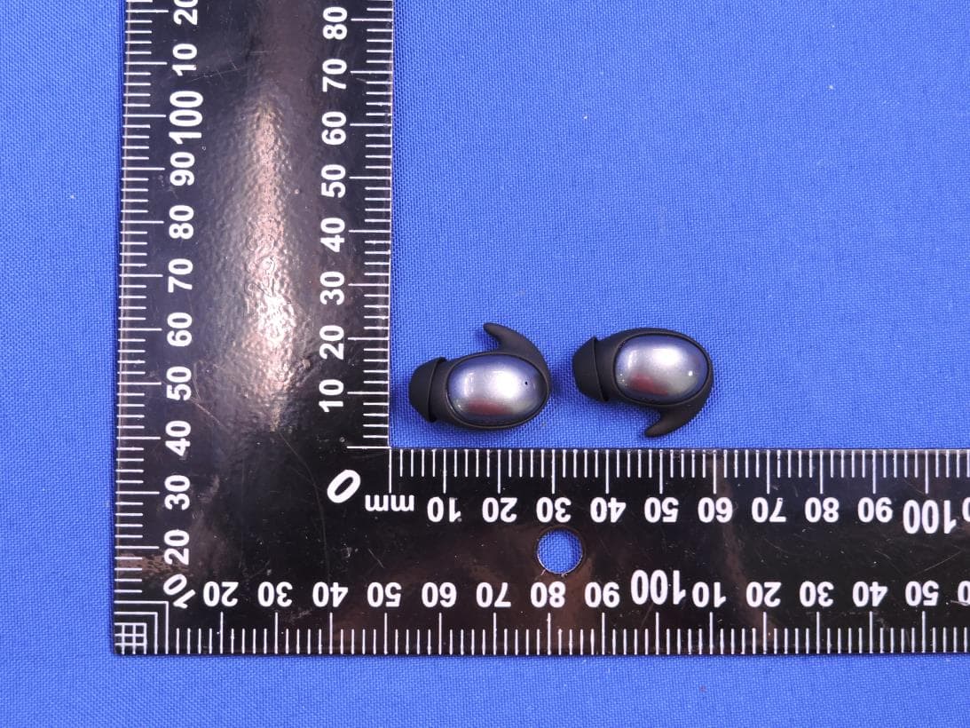
2AVD2-MH22280
Dec 19, 2025BLUETOOTH HEADPHONE
Equipment Class
DSS - Part 15 Spread Spectrum Transmitter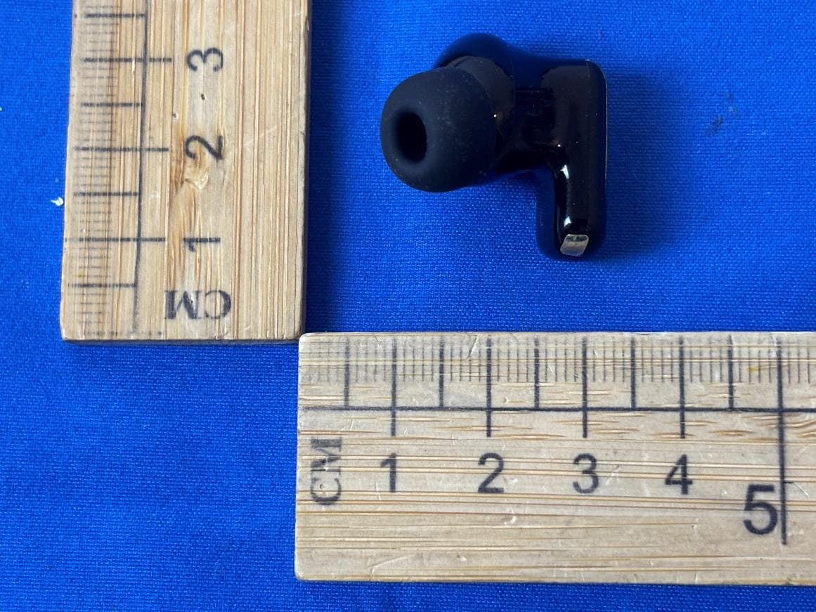
2AVD2-W55
Dec 17, 2025BLUETOOTH HEADPHONE
Equipment Class
DSS - Part 15 Spread Spectrum Transmitter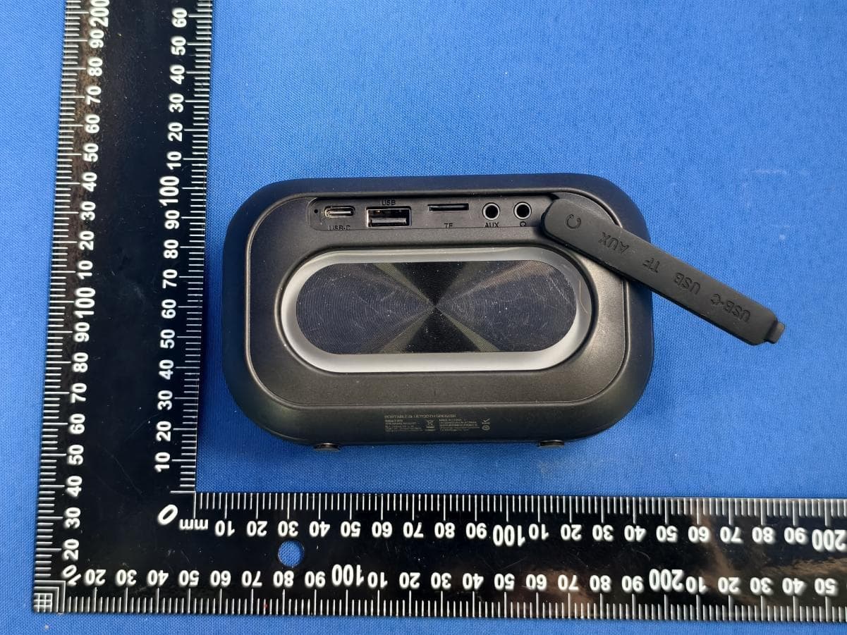
2AVD2-MS62110
Dec 16, 2025PORTABLE BLUETOOTH SPEAKER
Equipment Class
DSS - Part 15 Spread Spectrum Transmitter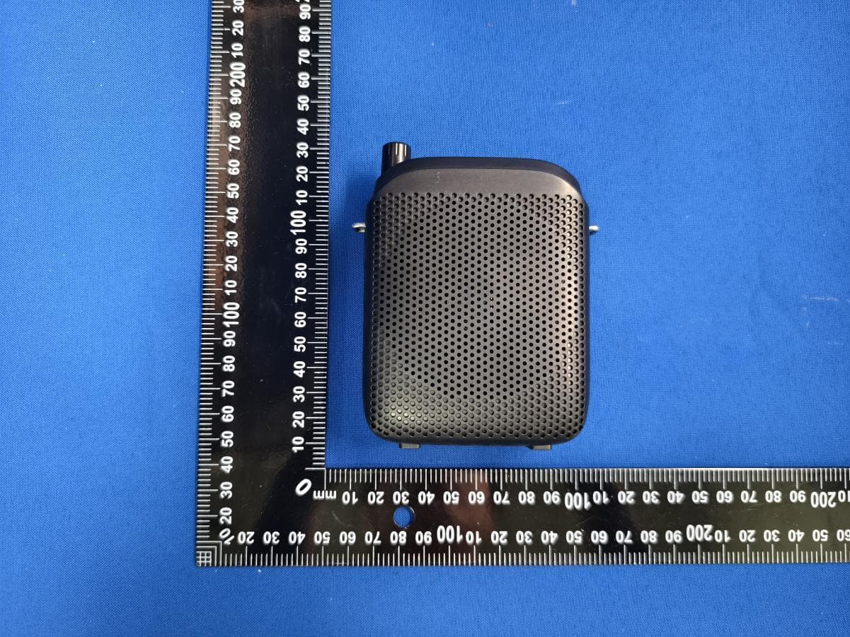
2AVD2-MS62144
Dec 12, 2025PORTABLE VOICE AMPLIFIER
Equipment Class
DSS - Part 15 Spread Spectrum Transmitter