2AVQS-17BT02Bluetooth module for consumer electronics equipment
Vestel Elektronik Sanayi ve Ticaret A.S.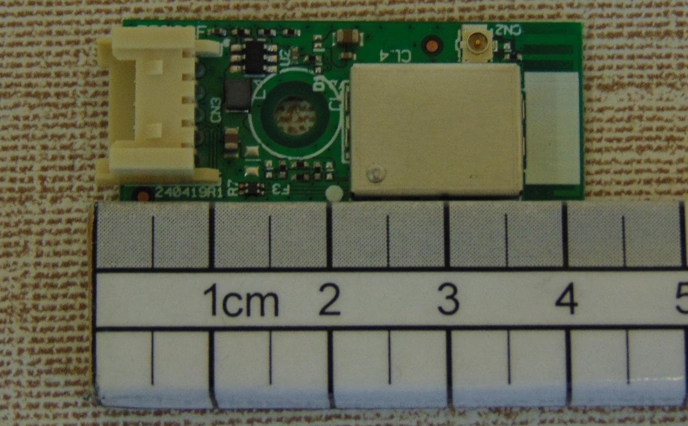
Click to zoom
Application Details
- Equipment Class
- DSS - Part 15 Spread Spectrum Transmitter
- Date of Grant
- Oct 07, 2020
- Application Purpose
- Original Equipment
- Date of Application
- Oct 07, 2020
- Equipment Note
- Bluetooth module for consumer electronics equipment
- Frequency Range
- 2402.00000000 - 2480.00000000
- Country
- Turkey
Documents & Files
Document Text
Text extracted from the exhibit documents filed with the FCC. Open a document above to read the original.
Users Manual
1 17BT02 Product Specification and User Manual 1. General Description The 17BT02 is used in Linux based platforms, it is working as a daughter board for connecting wireless sound devices and HID devices. It supports one connector to attach main boards. The socket uses USB signal interface at 5V supply voltage. Bluetooth module with Bluetooth 4.2 Modulations: GFSK, π/4 DQPSK, 8DPSK are used. Bluetooth Low Energy functionality disabled by firmware. 2. Features BT4.2 compliant A2DP source and HID profiles Printed PCB antenna USB interface 20Mhz Crystal 3. Key Specifications Main chipset CYW20705B, Cypress Frequency range 2402-2480 MHz Channels 0-78 Host interface USB 2 4. Electrical Specifications 4.1. Power supply voltages DC supply to module Min Typ Max VCC 4.75 V 5 V 5.25 V 5. RF Characteristic 5.1. Antenna Gain 2.4 Ghz Antenna 0 0.84 dBi 5.2. TX/RX Characteristic 17BT02 Channel DH1 3DH5 Tx Power (dBm) Rx Sensitivity (dBm) Tx Power (dBm) Rx Sensitivity (dBm) Ch_0 6,4 -88,5 6,26 -87,5 Ch_39 6,64 -88,5 6,55 -88 Ch_78 6,55 -88 6,48 -84 6. Mechanical Characteristics - Module dimension 40x17mm. 3 7. Pin Description Pin No. Pin Name I/O Pin Description 1 3D_sync I Panel 3D sync signal 50/60 Hz 2 VCC I VCC 5V 3 USB_DP I/O USB Communication Signal 4 USB_DN I/O USB Communication Signal 5 GND - Ground 8. Environmental 8.1. Operating Operating Temperature: 0 to 65 °C 8.2. Storage Temperature: -20 to 85 °C 9. Device Installation The module is a build in module. It will be used in-house production as an embedded device over USB 2.0 interface and there is no need any interaction with end-user. Positioning of the module is defined by assembly operator instructions for each product by Vestel. The module should be mounted by considering operating temperature. The temperature of the installation location should be between 0°C and 65 °C. The module can be integrated in any moblie/fixed host device. For portable devices a minimum seperation distance of 10 mm between the antenna and the human body shall be observed to aviod SAR requirements. The implementation of the module in a specific end-product should also be reviewed to ensure compliance with the FCC and IC requirements for SAR and MPE. The host integrator must follow the integration instructions provided by Vestel and ensure that the composite-system end product complies with the FCC requirements by a technical assessment or evaluation to the FCC rules and to KDB Publication 996369. Installed module’s FCC ID and IC numbers need to be clearly marked on the product with the following verbiage “Contains FCC ID: 2AVQS-17BT02” and “Contains IC: 25888-17BT02”. Host label shows the FCC and ISED identifier of the module. FCC and ISED identifier will be visible on the back cover of the host device. Also, the modular transmitter meet only FCC and ISED authorized for the specific ruleparts, and the host must show complains with his own rule parts. The module has been tested and approved as a Modular Radio in accordance with the appropriate FCC and IC standards. The supporting test data may be found in the modular test report. Since this module has been certified as a Modular Radio, this allows the end user to integrate this module into an end-product without the requirement of re-certifying the radio module. The module-integrator is responsible for the unintentional conducted and radiated emissions and must verify that the integrated product is compliant with the rules associated with unintentional radiators. The module integrator is also required to maintain an engineering record of the verification testing and declare on the product through proper labeling and marking that the device is compliant with these particular rules. Although already certified, radio tests according to KDB996369 clause 3.4 have to be carried out also. This device complies with part 15 of the FCC Rules and ISED licence-exempt RSS(s). Operation is subject to the following two conditions: This device may not cause harmful interference, and this device must accept any interference received, including interference that may cause undesired operation. 4 Changes or modifications not expressly approved by the party responsible for compliance could void the user’s authority to operate the equipment. Antenna connector port is not for use and disconnected at market products. Module is only allowed to use with the on board printed antenna. Vestel provides user notices in both English and French when the product is made available for sale and/or lease in Canada. This device contains licence-exempt transmitter(s)/receiver(s) that comply with Innovation, Science and Economic Development Canada’s licence-exempt RSS(s). Operation is subject to the following two conditions: 1. This device may not cause interference. 2. This device must accept any interference, including interference that may cause undesired operation of the device L'émetteur/récepteur exempt de licence contenu dans le présent appareil est conforme aux CNR d'Innovation, Sciences et Développement économique Canada applicables aux appareils radio exempts de licence. L'exploitation est autorisée aux deux conditions suivantes : 1. L'appareil ne doit pas produire de brouillage; 2. L'appareil doit accepter tout brouillage radioélectrique subi, même si le brouillage est susceptible d'en compromettre le fonctionnement. Software Installation The SW driver is already installed to host device software platform which is a Linux/Android OS.
Cover Letter(s)
Long/Short-term Confidentiality Request PHOENIX TESTLAB GmbH Date: 17.July.2020 Product Certification Königswinkel 10 D 32825 Blomberg FCC ID: 2AVQS-17BT02 To Whom It May Concerns, Pursuant to sections 0.457(d) and 0.459 of CFR 47 and to avoid premature release of sensitive information prior to marketing or release of the product to the public, we hereby request long-term confidential treatment of information accompanying this application as outlined below: ☒ Schematics ☒ Parts List ☒ Block Diagram ☐ Tune-Up Info ☐ Operational Description In addition we hereby request the following exhibits contained in this application to be temporarily (short-term confidentiality) withheld from the public disclosure ☐ for an initial period of days ☐ until: ☒ not applicable ☐ External Photos ☐ Test Setup Photos ☐ Internal Photos ☐ User Manual The above materials contain trade secrets and proprietary information not customarily released to the public. The public disclosure of these matters might be harmful to the applicant and provide unjustified benefits to its competitors. The applicant understands that pursuant to rule 0.457(d), disclosure of this application and all accompanying documentation will not be made before the date of the GRANT for this application. If you have any questions, please feel free to contact me. Yours sincerely, Tropmann Anton Authorised Agent Head of Laboratory STC Germany (formerly PKM electronic GmbH)
Cover Letter(s)
FCC ID: 2AVQS-17BT02 To the certification reviewer: We are hereby applying for full modular approval of the above-referenced FCC ID, based on compliance with all of the criteria as detailed below. Tropmann Anton Head of Laboratory (Authorized Agent) STC Germany (formerly PKM electronic GmbH) Part 15 Unlicensed Single Modular Transmitter Approval Justification per § 15.212 Requirement per § 15.212 Reference (1) The radio elements of the modular transmitter must have their own RF shielding. Shielding is provided by a ground plane on the printed wiring board and shielding housing. RF circuitry is fully shielded (2) The modular transmitter must have buffered modulation/data inputs (if such inputs are provided. All modulation and data inputs are buffered by circuitry on the transmitter chip. (3) The modular transmitter must have its own power supply regulation. Power supply regulation is provided by circuitry on the transmitter chip. (4) The modular transmitter must comply with the antenna and transmission system requirements of § 15.203, § 15.204(b) and § 15.204(c). The used antenna is a PCB antenna, which is not serviceable and can not be replaced by the user. UFL connectors are only placed with the test purposes and not placed when it is marketed. (5) The modular transmitter must be tested in a stand-alone configuration, i.e., the module must not be inside another device during testing for compliance with Part 15 parameters. Testing was performed with the module connected to an Extender Board that will not be marketed together with the module. (6) The modular transmitter must be equipped with either a permanently affixed label or must be capable of electronically displaying its FCC identification number. If the FCC ID is not visible when the module is installed inside another device, then the outside of the device into which the module is installed must also display a label referring to the enclosed module. FCC ID label is placed to the bottom side of the PCB. If module is installed to inside of the host devices, another label is placed outside of the host where FCC ID of the module is visible. (7) The modular transmitter must comply with any specific rules or operating requirements that ordinarily apply to a complete transmitter and the manufacturer must provide adequate instructions along with the module to explain any such requirements. A copy of these instructions must be included in the application for equipment authorization. The module is compliant with all applicable FCC rules. Compliance requirements are stated in the user manual exhibit. (8) The modular transmitter must comply with any applicable RF exposure requirements in its final configuration. Compliance with SAR / RF Exposure exemption limits for mobile/fixed host device, for portable devices a minimum separation distance of 15 mm between antenna and human body shall be observed. Details are addressed in SAR / RF Exposure letter.
External Photos
Attachment to Test-Report-No.: 20/01-0029 Product: Transmitting / Receiving System STC Germany GmbH, Ohmstrasse 1, 84160 Frontenhausen Tel.: + 49 (0) 8732 6381 - Fax: + 49 (0) 8732 2345 - E-mail: [email protected] - Website: www.pkm.eu.com o:\funk\20-01-0029\20-01-0029-fcc-ised-ext-photos.docx page 1 of 2 Photos of tested sample Attachment to Test-Report-No.: 20/01-0029 Product: Transmitting / Receiving System STC Germany GmbH, Ohmstrasse 1, 84160 Frontenhausen Tel.: + 49 (0) 8732 6381 - Fax: + 49 (0) 8732 2345 - E-mail: [email protected] - Website: www.pkm.eu.com o:\funk\20-01-0029\20-01-0029-fcc-ised-ext-photos.docx page 2 of 2
Internal Photos
Company Confidential Page 1 of 1 Internal photo of the 17BT02
Operational Description
1 17BT02 Description of Operation General Description The 17BT02 is used in Linux based platforms, it is working as a daughter board for connecting wireless sound devices and HID devices. It supports one connector to attach main boards. The socket uses USB signal interface at 5V supply voltage. Bluetooth module with Bluetooth 4.2 Modulations: GFSK, π/4 DQPSK, 8DPSK are used. Bluetooth Low Energy functionality disabled by firmware. Key Specifications Main chipset CYW20705B, Cypress Frequency range 2402-2480 MHz Channels 0-78 Host interface USB Antenna Gain Module has on board printed antennas with the given gain values in below. 2.4 Ghz Antenna 0 0.84 dBi
Test Report
Test report according to ISO/IEC 17025:2017 FCC (Federal Communications Commission) Test Firm Registration Number: 768032 Designation Number DE0022 ISED (Inovation, Science and Economic Development) CAB identifier: DE0012 ISED#: 6155A Electromagnetic compatibility Intentional Radiators STC Germany GmbH Ohmstrasse 1 84160 Frontenhausen, Germany Tel.: + 49 (0) 8732 6381 Fax: + 49 (0) 8732 2345 E-mail: [email protected] Test report no.: 20/01-0029 Page 1 of 79 pages Test report no.: 20/01-0029 Page 2 of 79 pages Table of contents 1. Client information ................................................................................................................................................... 3 2. Equipment under test (EUT) ................................................................................................................................... 3 3. Description of the Equipment under test and test conditions .................................................................................. 4 4. Performed measurements and results.................................................................................................................... 6 5. AC Mains conducted emissions ............................................................................................................................. 7 6. Radiated emission measurements ....................................................................................................................... 13 7. Operation within the band 902-928 MHz, 2400-2483,5 MHz and 5725-5850 MHz ............................................. 19 8. Test equipment ..................................................................................................................................................... 70 9. Test Setups .......................................................................................................................................................... 72 10. Measurement uncertainty ..................................................................................................................................... 76 11. Photos setup ........................................................................................................................................................ 77 12. Conclusions .......................................................................................................................................................... 78 13. Photos of tested sample ....................................................................................................................................... 79 Location of test facility: STC Germany GmbH Ohmstrasse 1 84160 Frontenhausen Germany Test report no.: 20/01-0029 Page 3 of 79 pages 1. Client information Name: Vestel Elektronik San ve Tic. A.S. Address: Organize Sanayi Bölgesi Vestel City, High-End 45030 MANISA TURKEY Name of contact: Mr. Andac Pamuk Telephone: +90 236 2332582 Fax: +90 236 2332584 E-mail: [email protected] 2. Equipment under test (EUT) 2.1 Identification of the EUT Equipment: Bluetooth Module (Bluetooth 4.2 without Bluetooth low energy) Model: 17BT02 Brand name: -/- Serial no.: -/- Manufacturer: Vestel Elektronik San ve Tic. A.S., Organize Sanayi Bölgesi, Vestel City, High-End, 45030 MANISA, TURKEY Country of origin: TURKEY Power rating: 4,75 V – 5,25 V nominal 5 V ⎓ via USB Highest frequency generated or used in the device or on which the device operates or tunes (MHz): 2.48 GHz Date Sample Received: 16.01.2020 Tests were performed: 17.02.2020 – 25.06.2020 2.2 Additional information about the EUT: -/- To duplicate parts of this test report needs the written confirmation of the test laboratory. The test results relate only to the above mentioned test sample(s). Test report no.: 20/01-0029 Page 4 of 79 pages 3. Description of the Equipment under test and test conditions FCC-ID: 2AVQS-17BT02 IC: 25888-17BT02 HVIN: 240419R1 Power: 4,75 V – 5,25 V nominal 5 V ⎓ via USB Cables: Cable to test adaptor 75 cm USB cable 100 cm Approx. Size (l x w x h): (42 x 12 x 8) mm Test conditions: The “Bluetooth Module (Bluetooth 4.2 without Bluetooth low energy) – 17BT02” (= equipment under test – EUT) had been tested, where applicable, in the following modes: (1) Bluetooth 4.2: Tx mode GFSK 2402.0 MHz (2) Bluetooth 4.2: Tx mode GFSK 2441.0 MHz (3) Bluetooth 4.2: Tx mode GFSK 2480.0 MHz (4) Bluetooth 4.2: Tx mode π/4-DQPSK 2402.0 MHz (5) Bluetooth 4.2: Tx mode π/4-DQPSK 2441.0 MHz (6) Bluetooth 4.2: Tx mode π/4-DQPSK 2480.0 MHz (7) Bluetooth 4.2: Tx mode 8DPSK 2402.0 MHz (8) Bluetooth 4.2: Tx mode 8DPSK 2441.0 MHz (9) Bluetooth 4.2: Tx mode 8DPSK 2480.0 MHz with controlled by a test software with maximum RF-output power and different data rate in order to find the worst case. Additional information: -/- RF Module Model Number: 17BT02 Frequency range: 2.400 GHz – 2.483,5 GHz Operating frequencies: 2.402 GHz – 2.480 GHz Module Tranmission Type: Bluetooth 4.2 (FHSS) Modulation: GFSK π/4-DQPSK 8DPSK Date Rates: 1 MBit/s 2 MBit/s 3 MBit/s Channel separation: 1 MHz 1 MHz 1 MHz Number of channels: 79 79 79 Spurious Emissions: radiated lowest margin to limit 37.2 dBμV/m @ 3 m 37.4 dBμV/m @ 3 m 37.9 dBμV/m @ 3 m Environmental conditions during tests: Ambient temperature: 20 °C Relative humitity 40 % Atmospheric pressure 965 mbar Antenna specification: Model: Printed PCB Antenna Gain: max. 0.84 dBi Type: External (with accessible antenna socket) Internal (integrated, PCB antenna) Test standard: - e-CFR Title 47 Chapter I Subchapter A Part 15 Subpart C §15.247: Operation within the bands 902-928 MHz, 2400-2483.5 MHz, and 5725-5850 MHz - RSS-247 issue 02 February 2017 Digital Transmission Systems (DTSs), Frequency Hopping Systems (FHSs) and Licence-Exempt Local Area Network (LE-LAN) Devices Test report no.: 20/01-0029 Page 5 of 79 pages Channel List Bluetooth 4.2 Channel Frequency (MHz) Channel Frequency (MHz) 0 2402 42 2444 1 2403 43 2445 2 2404 44 2446 3 240…
Text truncated - open the document above for the full version.
Test Report
Test report no.: 20/01-0029 Page 41 of 79 pages 7.6. Band-Edges Measurement / Out of Band Emissions Applied standards -e-CFR Title 47 Chapter I Subchapter A Part 15 Subpart C §15.247 (d) -RSS-247 issue 2 Section 5.5 Limit In any 100 kHz bandwidth outside the frequency band in which the spread spectrum or digitally modulated intentional radiator is operating, the radio frequency power that is produced by the intentional radiator shall be at least 30 dB below that in the 100 kHz bandwidth within the band that contains the highest level of the desired power. Attenuation below the general limits specified in § 15.209 and RSS-Gen Table 5 is not required. Emissions which fall in the restricted bands, as defined in §15.205 Restricted Bands of operation as well as in restricted bands of the RSS-Gen Issue 5 (see Section 8.10 Restricted Frequency Bands) and must also comply with the radiated emission limits specified in §15.209 Radiated emission limits as well as the limits specified in RSS-Gen Table 5. Test equipment and test set up Test equipment used for Band Edge measurements as given in clause Test equipment of this report. Test setup used for Band Edge measurements as given in clause Test setups of this report. Description The band edge is measured at an amplitude level reduced from the reference level by a specified ratio. The reference level is the level of the highest amplitude signal observed from the transmitter at the fundamental frequency. Detector function selection and bandwidth For the measurement, an EMI test receiver that have CISPR peak detector was used. Frequency range: Bandwidth See measurement graph RBW: 100 kHz VBW: 300 kHz Measurement The Measurement was performed on: 25.06.2020 Test report no.: 20/01-0029 Page 42 of 79 pages Higher Band Edge - GFSK CH. 78 – radiated Test report no.: 20/01-0029 Page 43 of 79 pages Test report no.: 20/01-0029 Page 44 of 79 pages Lower Band Edge - GFSK CH. 0 – radiated Test report no.: 20/01-0029 Page 45 of 79 pages Test report no.: 20/01-0029 Page 46 of 79 pages Higher Band Edge - π/4-DQPSK CH. 78 – radiated Test report no.: 20/01-0029 Page 47 of 79 pages Test report no.: 20/01-0029 Page 48 of 79 pages Lower Band Edge - π/4-DQPSK CH. 0 – radiated Test report no.: 20/01-0029 Page 49 of 79 pages Test report no.: 20/01-0029 Page 50 of 79 pages Higher Band Edge - 8DPSK CH. 78 – radiated Test report no.: 20/01-0029 Page 51 of 79 pages Test report no.: 20/01-0029 Page 52 of 79 pages Lower Band Edge - 8DPSK CH. 0 – radiated Test report no.: 20/01-0029 Page 53 of 79 pages Test report no.: 20/01-0029 Page 54 of 79 pages Hopping mode Band Edge Measurement were also performed in Hopping mode. For hopping mode the 8DPSK mode was found as worst case and documented in this report. Test report no.: 20/01-0029 Page 55 of 79 pages Test report no.: 20/01-0029 Page 56 of 79 pages Test report no.: 20/01-0029 Page 57 of 79 pages Results From the measurement data obtained, the tested sample was considered to have COMPLIED with the requirements for the Band Edges / Out of Band Emission. Test report no.: 20/01-0029 Page 58 of 79 pages 7.7. Occupancy Time Applied standards -e-CFR Title 47 Chapter I Subchapter A Part 15 Subpart C §15.247 (a) (1) (iii) -RSS-247 issue 2 Section 5.1 (d) Test Requirements The average time of occupancy on any channel shall not be greater than 0.4 seconds within a period of 0.4 seconds multiplied by the number of hopping channel employed. No requirements for Digital Transmission System. Discription [Test time period] = [Limit] x [Channels] = 0.4 s x 79 = 31.6 s Measurement The Measurement was performed on: 18.02.2020 DH5 / 3-DH5 Packet DH5 Packet permit maximum 1600/79/6 = 3.37 hops per second in each channel (5 time slots RX, 1 time slot TX). The Dwell time is the time duration of the pulse times 3.37 hops/sec. x 31.6 sec. = 106.6 hops within 31.6 seconds Pulse duration of Lowest Channel Test report no.: 20/01-0029 Page 59 of 79 pages Pulse duration of Middle Channel Pulse duration of Highest Channel Test report no.: 20/01-0029 Page 60 of 79 pages DH3 / 3-DH3 Packet: DH3 Packet permit maximum 1600/79/4 = 5.06 hops per second in each channel (3 time slots RX, 1 time slot TX). The Dwell time is the time duration of the pulse times 5.06 hops/sec. x 31.6 sec. = 160 hops within 31.6 seconds Pulse duration of Lowest Channel Pulse duration of Middle Channel Test report no.: 20/01-0029 Page 61 of 79 pages Pulse duration of Highest Channel Test report no.: 20/01-0029 Page 62 of 79 pages DH1 /2-DH1 Packet: DH1 Packet permit maximum 1600/79/2 = 10.12 hops per second in each channel (1 time slots RX, 1 time slot TX). The Dwell time is the time duration of the pulse times 10.12 hops/sec. x 31.6 sec. = 320 hops within 31.6 seconds Pulse duration of Lowest Channel Pulse duration of Middle Channel Test report no.: 20/01-0029 Page 63 of 79 pages Pulse duration of Highest Channel Time of occupancy (Dwell Time): Data Packet Frequency [MHz] Hops in Test time period Pulse Duration [ms] Dwell Time [s] Limit [s] Result DH5/3-DH5 2402 106.6 2.895 0.309 0.400 PASS DH5/3-DH5 2441 106.6 2.895 0.309 0.400 PASS DH5/3-DH5 2480 106.6 2.895 0.309 0.400 PASS DH3/3-DH3 2402 160 1.635 0.262 0.400 PASS DH3/3-DH3 2441 160 1.635 0.262 0.400 PASS DH3/3-DH3 2480 160 1.635 0.262 0.400 PASS DH1/2-DH1 2402 320 0.385 0.123 0.400 PASS DH1/2-DH1 2441 320 0.385 0.123 0.400 PASS DH1/2-DH1 2480 320 0.385 0.123 0.400 PASS Formula: [Dwell time] = [Hops in Test time period.] x [Pulse Duration] Results From the measurement data obtained, the tested sample was considered to have COMPLIED with the requirements for the Time of occupancy (dwell time). Test report no.: 20/01-0029 Page 64 of 79 pages 7.8. 99% Power Bandwidth Applied standards -RSS-Gen issue 5 Section 6.7 Test equipment and test set up Test equipment used for conducted measurements as given in clause Test equipment of this report. Test setup used for conducted measurements as given in clause Test setups of this report. Descriptio…
Text truncated - open the document above for the full version.
Test Setup Photos
Attachment to Test-Report-No.: 20/01-0029 Product: Transmitting / Receiving System STC Germany GmbH, Ohmstrasse 1, 84160 Frontenhausen Tel.: + 49 (0) 8732 6381 - Fax: + 49 (0) 8732 2345 - E-mail: [email protected] - Website: www.pkm.eu.com o:\reports\reports ab 05-2015\20-01-0029-fcc-ised-rep-photos test setup.docx page 1 of 7 Photos Test Setup Conducted Mains emissions Attachment to Test-Report-No.: 20/01-0029 Product: Transmitting / Receiving System STC Germany GmbH, Ohmstrasse 1, 84160 Frontenhausen Tel.: + 49 (0) 8732 6381 - Fax: + 49 (0) 8732 2345 - E-mail: [email protected] - Website: www.pkm.eu.com o:\reports\reports ab 05-2015\20-01-0029-fcc-ised-rep-photos test setup.docx page 2 of 7 Attachment to Test-Report-No.: 20/01-0029 Product: Transmitting / Receiving System STC Germany GmbH, Ohmstrasse 1, 84160 Frontenhausen Tel.: + 49 (0) 8732 6381 - Fax: + 49 (0) 8732 2345 - E-mail: [email protected] - Website: www.pkm.eu.com o:\reports\reports ab 05-2015\20-01-0029-fcc-ised-rep-photos test setup.docx page 3 of 7 Radiated emissions Tested frequency range 9 kHz – 30 MHz Attachment to Test-Report-No.: 20/01-0029 Product: Transmitting / Receiving System STC Germany GmbH, Ohmstrasse 1, 84160 Frontenhausen Tel.: + 49 (0) 8732 6381 - Fax: + 49 (0) 8732 2345 - E-mail: [email protected] - Website: www.pkm.eu.com o:\reports\reports ab 05-2015\20-01-0029-fcc-ised-rep-photos test setup.docx page 4 of 7 Tested frequency range 30 MHz -1.000 MHz Attachment to Test-Report-No.: 20/01-0029 Product: Transmitting / Receiving System STC Germany GmbH, Ohmstrasse 1, 84160 Frontenhausen Tel.: + 49 (0) 8732 6381 - Fax: + 49 (0) 8732 2345 - E-mail: [email protected] - Website: www.pkm.eu.com o:\reports\reports ab 05-2015\20-01-0029-fcc-ised-rep-photos test setup.docx page 5 of 7 Tested frequency range > 1 GHz Attachment to Test-Report-No.: 20/01-0029 Product: Transmitting / Receiving System STC Germany GmbH, Ohmstrasse 1, 84160 Frontenhausen Tel.: + 49 (0) 8732 6381 - Fax: + 49 (0) 8732 2345 - E-mail: [email protected] - Website: www.pkm.eu.com o:\reports\reports ab 05-2015\20-01-0029-fcc-ised-rep-photos test setup.docx page 6 of 7 RF-conducted measurements EUT EUT Attachment to Test-Report-No.: 20/01-0029 Product: Transmitting / Receiving System STC Germany GmbH, Ohmstrasse 1, 84160 Frontenhausen Tel.: + 49 (0) 8732 6381 - Fax: + 49 (0) 8732 2345 - E-mail: [email protected] - Website: www.pkm.eu.com o:\reports\reports ab 05-2015\20-01-0029-fcc-ised-rep-photos test setup.docx page 7 of 7
Contact Information
Applicant
Andac PAMUK(CE Test and Certification Manager)
Test Firm
STC Germany GmbH (former PKM electronic GmbH)Klaus Gisbert
Technical Specifications
| # | Rule Parts | Frequency Range | Power Output |
|---|---|---|---|
| 1 | 15C | 2.40 GHz - 2.48 GHz | 4.00 mW |
Other Applications from Vestel Elektronik Sanayi ve Ticaret A.S.
2AVQS-32FHA570
Apr 17, 2024Remote controlled colour TV
Equipment Class
DSS - Part 15 Spread Spectrum Transmitter
2AVQS-17WFM26Y
Jan 09, 202417WFM26Y WI-FI + BT combo module
Equipment Class
DTS - Digital Transmission System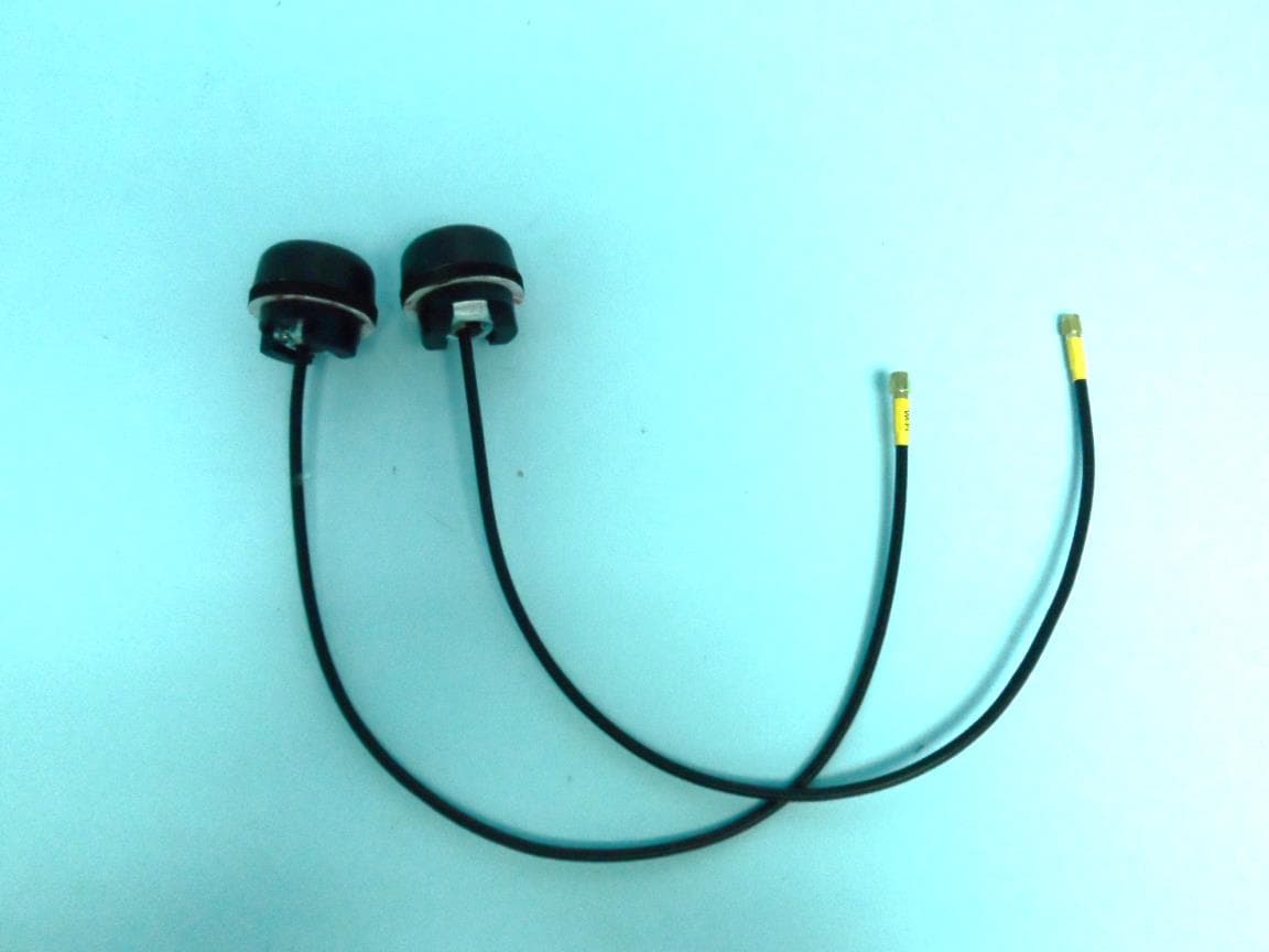
2AVQS-17WFM25
Mar 02, 2022Wi-Fi + BT Combo module
Equipment Class
DSS - Part 15 Spread Spectrum Transmitter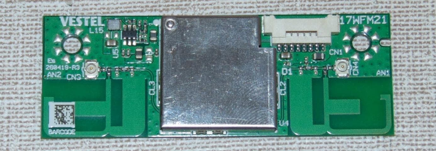
2AVQS-17WFM21
Feb 24, 2021Wi-Fi module
Equipment Class
DTS - Digital Transmission System