2AWONUT88875Smart LED Flood Light
Shenzhen Ustellar Technology Ltd.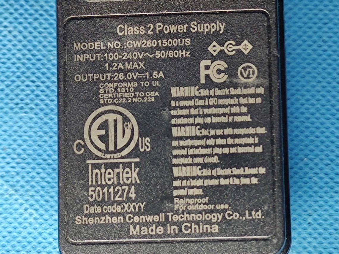
Click to zoom
Application Details
- Equipment Class
- DTS - Digital Transmission System
- Date of Grant
- Jun 12, 2022
- Application Purpose
- Original Equipment
- Date of Application
- Jun 12, 2022
- Equipment Note
- Smart LED Flood Light
- Frequency Range
- 2412.00000000 - 2462.00000000
- Country
- China
Documents & Files
Document Text
Text extracted from the exhibit documents filed with the FCC. Open a document above to read the original.
Users Manual
Smart LED Flood Light User Guide Manual Version: UT88875-RGBW / V1.0 (QJOLVK Smart LED Flood Light User Guide Before installation, let’s know how the whole thing works. Step One: Install the smart flood light. Step Two: Fundamental set-up-Connect smart LED flood light to Smart Life App. Step Three & Four: Optional set-up - Connect Smart Life App to Amazon Alexa or Google Assistant. After completing Step Two, you can remote control the light on Smart Life App. After completing Step Three and Four, you can voice control the light with Alexa or Google Assistant. This manual consists of Four parts. Part One - How to install the light ?··························2 - 7 Part Two - How to pair the light to Smart Life app?············· 8 - 13 Part Three - How to control the light with Amazon Alexa?······ 14 - 16 Part Four - How to control the light with Google Assistant? ·····17 - 18 Voice Control Voice Control 1 (QJOLVK Part One - How to insall the light? Warning (1) Please check if the light and the parts are intact before installation. (2) Make sure to cut off power before installation. (3) Please do not place this light in corrosive conditions. (4) If there is any damage to the cord, please cut off the power and stop using it immediately. (5) Please do not retrofit the light within the warranty period. (6) To ensure the light works properly, please use the voltage indicated on the packing. 2 Model Total Wattage Max Luminous Flux Input Voltage Color Color Temperature Frequency Bean Angle Working temperature Waterproof Rating UT88875 40W 4000lm RGB, Warm White 2700K 50/60Hz 120° -20~40燠 AC120V 1. Parameters Flood Lights IP66 Power Adapter IP44 (QJOLVK 2. Components 3 Package Includes: Flood Light Power Adapter Flood Lights Power Adapter Ground Sticks Screws L Shaped Hex Key Wrench User Manual x 6 x 1 x 1 x 1 x 6 x 7 (QJOLVK 3. Dimension 4 14cm/5.5in 3m/10ft3m/10ft3m/10ft 3m/10ft3m/10ft 3m/10ft 3.2cm/1.26in 10cm/4.0in 12cm/4.7in 16cm/6.3in Note: 1. The flood lights and cables can not be extended, Do not cut the cable. 2. Use this product with the provided power adapter only. 3. The power adapter is IP44 grade waterproof, which can not be directly used outdoor. Please connect to a indoor socket, or use a waterproof box. 4. The flood lights are IP66 grade waterproof, which can be used outdoor. But do not immerse the lights in water. (QJOLVK 5 4. Installation Step A: According to the spacing of two screw bits on the bracket, drill two holes on the mounting panel. A B Note: Maximum mounting height is over 5m. Step B: Aim the bracket at the holes and fix it with two bolts (not included). Step C: Adjust the lighting direction up or down as per your need and plug in to power the light on. C Scenario 1: (QJOLVK 6 Step A: Attach the ground stick to the Flood light, with the screw provided in the package. A B Step B: Tighten the screw with the Hex Key Wrench. Step C: Adjust the lighting direction up or down as per your need and plug in to power the light on. C Scenario 2: 7 01 Make sure that the distance between the light and the object being lits is more than 1 meter, so as to avoid high temperature caused by short distance. (1) This light is waterproof and damp proof. It is protected against the rain, but it cannot be immersed in water. (2) The mounting position of this light should be able to bear at least 10 times as heavy as the light. (3) This light should be used in condition that is good for heat dissipation. Its working temperature should be less than 45°C Too high the working temperature will cause serious lumen depression and affect lifespan of the light. Note: The light source of this Iuminaire is not replaceable. Limitation of Indoor and Outdoor Use 01 FCC ID: 2AWONUT88875 This device complies with part 15 of the FCC rules. Operation is subject to the following two conditions: (1) this device may not cause harmful interference, and (2) this device must accept any interference received, including interferencethat may cause undesired operation. This equipment complies with FCC radiation exposure limits set forth for an uncontrolled environment. This equipment should be installed and operated with minimum distance of 20 cm between the radiator and your body. This transmitter must not be co-located or operating in conjunction with any other antenna or transmitter. (QJOLVK (QJOLVK Step A : Smart Life app installation Please choose either way below to download and install the app. (1) As per your phone system, choose the QR code to scan. (2) Search keyword ‘Smart Life’ in Apple Store or Google Play. Step B: Create an account on Smart Life and login. Note: Please keep your account and password in mind for Alexa or Google Assistant App pairing later. Part Two - How to pair the light to Smart Life app? 8 The WiFi signal receiving module is built in the first flood light head (the one close to the power adapter). The maximum wireless connection distance is up to 65ft/20m. Before starting the paring, please make sure to turn on the Bluetooth and WiFi on your phone. The smart light only supports 2.4GHz WiFi network, not 5.0GHz. Please make sure the working network is 2.4GHz, and your phone is connected to it. If your WiFi router supports both 2.4GHz and 5.0GHz, please separate the two frequency bands in the router settings, and select the 2.4GHz for connection. (QJOLVK Step C : Add the light to Smart Life App 1. Tap ‘+’ button on top right corner to add devices. Tap ‘Lighting’, then choose ‘PIR Light (BLE+Wi-Fi)’ to add the lights. 9 2. Power on the light with your own switch. Repeatedly turn on-off-on-off -on-off-on switch (3 times) to activate the light into rapid blinking status (about 0.5s per blink). Please make sure to keep an interval over 2 seconds between each turn-on and turn-off. Then click the ‘Next’ button on this page. Find the lighting devices and click ‘+’. (QJOLVK 3. Choose your WiFi network, enter your password, and tap the ‘Next’ button. Then give a name to the light and tap the ‘Done’ …
Text truncated - open the document above for the full version.
Attestation Statements
QA-FR-170-B Shenzhen Ustellar Technology Ltd. Add: Rm.C306, 3/F,C Bldg., Youth Entrepreneur Hub, Jianshe East Road, Qinghua Community,Longhua ,Shenzhen,China Tel: 0755-21008194 Fax: 0755-21008194 Email: [email protected] Date: 2022-05-25 FEDERAL COMMUNICATIONS COMMISSION Authorization and Evaluation Division 7435 Oakland Mills Road Columbia, MD 21046 Dear Sir/Madam: We , Shenzhen Ustellar Technology Ltd., hereby authorizes China Certification ICT Co., Ltd (Dongguan) to act as a laboratory for testing and test report generation for the following project(s): ( Product name:Smart LED Flood Light, FCC ID:2AWONUT88875) The mainchip BK7231N which suppo rts 2.4G WIFI ,BT and BLE Mode, But for this device, only 802.11b/g/n20/n40 and BLE(1M) were active, the others was disabled by software, Sincerely Yours, Client’s signature Printed Name: Liu shaolin Title: Engineer
Cover Letter(s)
QA-FR-171-A Shenzhen Ustellar Technology Ltd. Add: Rm.C306, 3/F,C Bldg., Youth Entrepreneur Hub, Jianshe East Road, Qinghua Community,Longhua ,Shenzhen,China Tel: 0755-21008194 Fax: 0755-21008194 Email: [email protected] FCC Confidential Authorization Date: 2022-05-25 FEDERAL COMMUNICATIONS COMMISSION Authorization and Evaluation Division 7435 Oakland Mills Road Columbia, MD 21046 Subject: Confidentiality Request regarding application for certification of FCC ID: 2AWONUT88875 In accordance with Sections 0.457 and 0.459 of the Commission’s Rules, (Shenzhen Ustellar Technology Ltd.) hereby requests long-term confidential treatment of information accompanying this application as outlined below: • Block Diagram • Schematics • Operation Description The above materials contain proprietary and confidential information not customarily released to the public. The public disclosure of these materials provides unjustified benefits to its competitors in the market. Sincerely, Signature: Printed Name: Liu shaolin Title: Engineer
Cover Letter(s)
QA-FR-170-B Shenzhen Ustellar Technology Ltd. Add: Rm.C306, 3/F,C Bldg., Youth Entrepreneur Hub, Jianshe East Road, Qinghua Community,Longhua ,Shenzhen,China Tel: 0755-21008194 Fax: 0755-21008194 Email: [email protected] FCC Authorization Date: 2022-05-25 FEDERAL COMMUNICATIONS COMMISSION Authorization and Evaluation Division 7435 Oakland Mills Road Columbia, MD 21046 Subject: Agent Authorization To whom it may concern: We , Shenzhen Ustellar Technology Ltd., Hereby authorizes China Certification ICT Co., Ltd (Dongguan) to act on its behalf in all matters relating to application for Equipment authorization, including the signing of all documents relating to these matters. All acts carried out by China Certification ICT Co., Ltd (Dongguan) on our behalf shall have the same effect as our own action. We, the undersigned, hereby certify that we are not subject to a denial of federal benefits, that includes FCC benefits, pursuant to Section 5301 of the Anti-Drug Abuse Act of 1988, 21 U.S.C. 862. This authorization is valid until further written notice from the applicant. Sincerely Yours, Client’s signature Printed Name: Liu shaolin Title: Engineer
External Photos
EXHIBIT B - EUT EXTERNAL PHOTOGRAPHS EUT
ID Label/Location Info
US 35
Internal Photos
EXHIBIT C - EUT INTERNAL PHOTOGRAPHS Uncover Chip1 Antenna Chip2 Chip3 Chip4 Chip5 Chip6 Chip7 Chip8
RF Exposure Info
China Certification ICT Co., Ltd (Dongguan) Report No.: CR22040069-00A Page 58 of 58 5. RF EXPOSURE EVALUATION 5.1 MAXIMUM PERMISSIBLE EXPOSURE (MPE) 5.1.1 Applicable Standard FCC §15.247 (i) & §1.1310 & §2.1091 Systems operating under the provisions of this section shall be operated in a manner that ensures that the public is not exposed to radio frequency energy levels in excess of the Commission's guidelines. See §1.1307(b)(1) of this chapter. Limits for Maximum Permissible Exposure (MPE) (§1.1310, §2.1091) (B) Limits for General Population/Uncontrolled Exposure Frequency Range (MHz) Electric Field Strength (V/m) Magnetic Field Strength (A/m) Power Density (mW/cm 2 ) Averaging Time (minutes) 0.3–1.34 614 1.63 *(100) 30 1.34–30 824/f 2.19/f *(180/f²) 30 30–300 27.5 0.073 0.2 30 300–1500 / / f/1500 30 1500–100,000 / / 1.0 30 f = frequency in MHz; * = Plane-wave equivalent power density; According to §1.1310 and §2.1091 RF exposure is calculated. 5.1.2 Procedure Prediction of power density at the distance of the applicable MPE limit S = PG/4R² = power density (in appropriate units, e.g. mW/cm 2 ); P = power input to the antenna (in appropriate units, e.g., mW); G = power gain of the antenna in the direction of interest relative to an isotropic radiator, the power gain factor, is normally numeric gain; R = distance to the center of radiation of the antenna (appropriate units, e.g., cm); 5.3 Measurement Result Operation Modes Frequency (MHz) Antenna Gain Conducted output power including Tune-up Tolerance Evaluation Distance (cm) Power Density (mW/cm 2 ) MPE Limit (mW/cm 2 ) (dBi) (numeric) (dBm) (mW) Wi-Fi 2412-2462 2.00 1.58 24 251.19 20 0.0790 1 BLE 2402-2480 2.00 1.58 2 1.58 20 0.0005 1 Note: The Wi-Fi and BLE can’t transmit simultaneously. Result: The device meet FCC MPE at 20 cm distance. ===== END OF REPORT =====
Test Report
TEST REPORT Applicant: Shenzhen Ustellar Technology Ltd. Address: Rm.C306, 3/F,C Bldg., Youth Entrepreneur Hub, Jianshe East Road, Qinghua Community,Longhua ,Shenzhen,China FCC ID: 2AWONUT88875 Product Name: Smart LED Flood Light Model Number: UT88875 Standard(s): 47 CFR Part 15, Subpart C(15.247) ANSI C63.10-2013 KDB 558074 D01 15.247 Meas Guidance v05r02 The above equipment has been tested and found compliant with the requirement of the relative standards by China Certification ICT Co., Ltd (Dongguan) Report Number: CR22040069-00A Date Of Issue: 2022-05-25 Reviewed By: Sun Zhong Title: Manager Test Laboratory: China Certification ICT Co., Ltd (Dongguan) No. 113, Pingkang Road, Dalang Town, Dongguan, Guangdong, China Tel: +86-769-82016888 China Certification ICT Co., Ltd (Dongguan) Report No.: CR22040069-00A Page 2 of 58 Test Facility The Test site used by China Certification ICT Co., Ltd (Dongguan) to collect test data is located on the No. 113, Pingkang Road, Dalang Town, Dongguan, Guangdong, China. The lab has been recognized as the FCC accredited lab under the KDB 974614 D01 and is listed in the FCC Public Access Link (PAL) database, FCC Registration No. : 442868, the FCC Designation No. : CN1314. The lab has been recognized by Innovation, Science and Economic Development Canada to test to Canadian radio equipment requirements, the CAB identifier: CN0123. Declarations China Certification ICT Co., Ltd (Dongguan) is not responsible for the authenticity of any test data provided by the applicant. Data included from the applicant that may affect test results are marked with a triangle symbol “▲”. Customer model name, addresses, names, trademarks etc. are not considered data. Unless otherwise stated the results shown in this test report refer only to the sample(s) tested. This report cannot be reproduced except in full, without prior written approval of the Company. This report is valid only with a valid digital signature. The digital signature may be available only under the Adobe software above version 7.0. This report may contain data that are not covered by the accreditation scope and shall be marked with an asterisk “★”. China Certification ICT Co., Ltd (Dongguan) Report No.: CR22040069-00A Page 3 of 58 CONTENTS TEST FACILITY .......................................................................................................................................... 2 DECLARATIONS .......................................................................................................................................... 2 1. GENERAL INFORMATION .................................................................................................... 5 1.1 PRODUCT DESCRIPTION FOR EQUIPMENT UNDER TEST (EUT) ....................................................... 5 1.2 DESCRIPTION OF TEST CONFIGURATION ........................................................................................... 8 1.2.2 Support Equipment List and Details .............................................................................................................. 8 1.2.3 Support Cable List and Details ...................................................................................................................... 8 1.2.4 Block Diagram of Test Setup ......................................................................................................................... 9 1.3 MEASUREMENT UNCERTAINTY ........................................................................................................ 11 2. SUMMARY OF TEST RESULTS .......................................................................................... 12 3. REQUIREMENTS AND TEST PROCEDURES .................................................................. 13 3.1 AC LINE CONDUCTED EMISSIONS .................................................................................................... 13 3.1.1 Applicable Standard ..................................................................................................................................... 13 3.1.2 EUT Setup.................................................................................................................................................... 14 3.1.3 EMI Test Receiver Setup ............................................................................................................................. 14 3.1.4 Test Procedure ............................................................................................................................................. 15 3.1.5 Corrected Amplitude & Margin Calculation ................................................................................................ 15 3.2 RADIATION SPURIOUS EMISSIONS .................................................................................................... 16 3.2.1 Applicable Standard ..................................................................................................................................... 16 3.2.2 EUT Setup.................................................................................................................................................... 16 3.2.3 EMI Test Receiver & Spectrum Analyzer Setup ......................................................................................... 17 3.2.4 Test Procedure ............................................................................................................................................. 17 3.2.5 Corrected Amplitude & Margin Calculation ................................................................................................ 17 3.3 6 DB EMISSION BANDWIDTH: ............................................................................................................ 18 3.3.1 Applicable Standard ..................................................................................................................................... 18 3.3.2 EUT Setup..................................................…
Text truncated - open the document above for the full version.
Test Setup Photos
EXHIBIT D - TEST SETUP PHOTOGRAPHS Conducted Emissions Front View Conducted Emissions Side View Radiated Emission Below 1GHz View Radiated Emission Above 1GHz View
Contact Information
Applicant
li changchun(Power Supervisor)
Test Firm
CHINA CERTIFICATION ICT CO., LTD (DONGGUAN)Tanie Ou
[email protected]0086 0769 86858888
Technical Specifications
| # | Rule Parts | Frequency Range | Power Output |
|---|---|---|---|
| 2 | 15C | 2.41 GHz - 2.46 GHz | 251.00 mW |
Other Applications from Shenzhen Ustellar Technology Ltd.
2AWONNTF92
Jul 07, 2024Smart LED Flood Light
Equipment Class
DTS - Digital Transmission System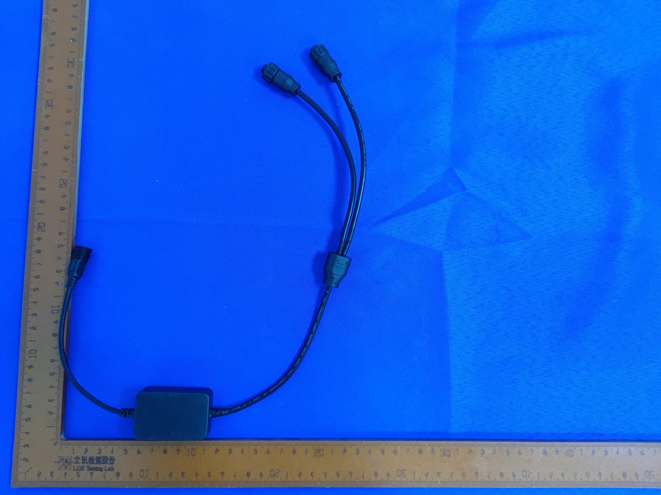
2AWON-NVS-WF01
Jul 24, 2023Permanent Outdoor Lights
Equipment Class
DTS - Digital Transmission System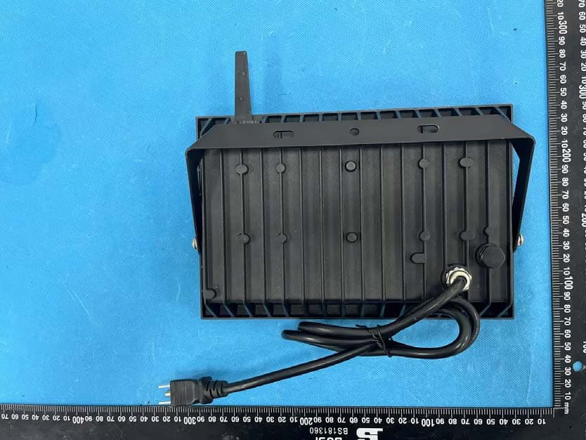
2AWONNTF81C
May 17, 2023Smart Flood Light
Equipment Class
DTS - Digital Transmission System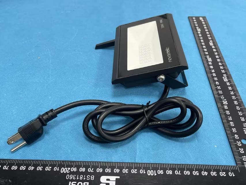
2AWONNTF80C
May 17, 2023Smart Flood Light
Equipment Class
DTS - Digital Transmission System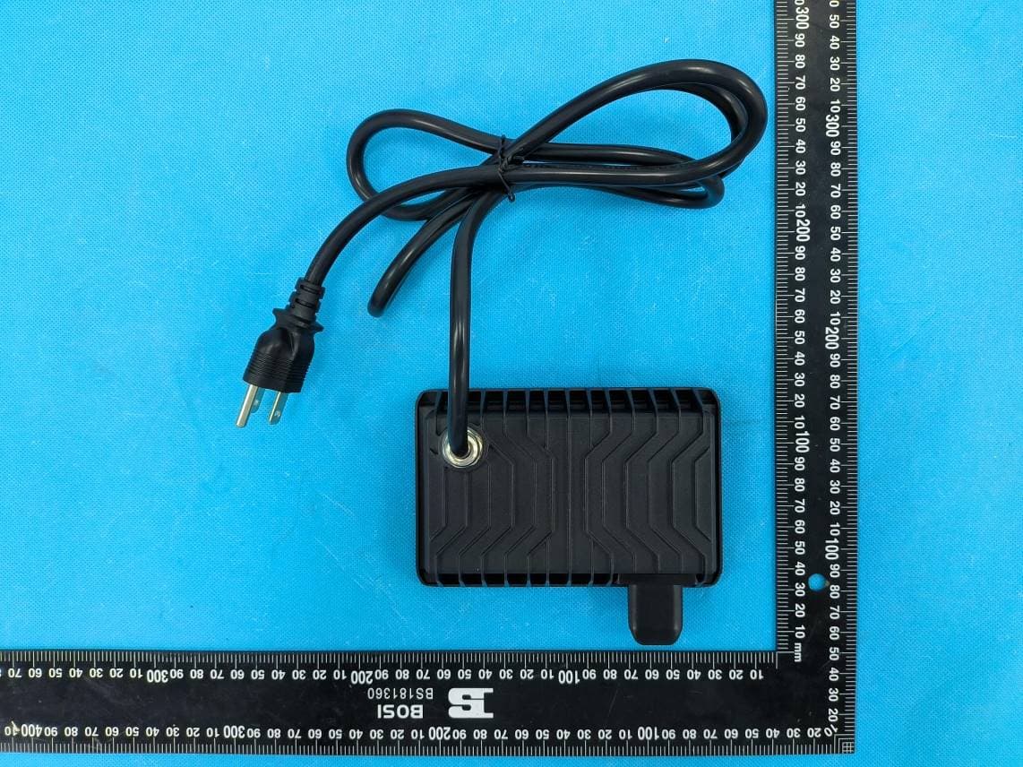
2AWONNTF96
Dec 13, 2022Smart Flood Light
Equipment Class
DTS - Digital Transmission System