2AWY6-MT7668BUWIFI Bluetooth module
EXPRESS LUCK INDUSTRIAL (SHENZHEN) LIMITED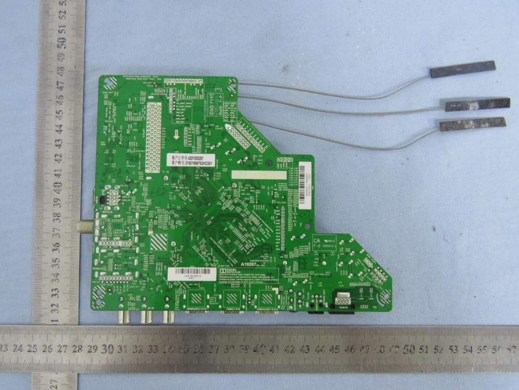
Click to zoom
Application Details
- Equipment Class
- NII - Unlicensed National Information Infrastructure TX
- Date of Grant
- Sep 23, 2020
- Application Purpose
- Original Equipment
- Date of Application
- Sep 17, 2020
- Equipment Note
- WIFI Bluetooth module
- Frequency Range
- 5745.00000000 - 5825.00000000
- Country
- China
Documents & Files
Document Text
Text extracted from the exhibit documents filed with the FCC. Open a document above to read the original.
Users Manual
EXPRESS LUCK INDUSTRIAL (SHENZHEN) LIMITED User Manual Model Name: SKI.WB7638U.1_MT7668BU REVISION HISTORY VERSION DATE BOARD ID PAGE DESCRIPTION AUTHOR V0 2019.07.23 TD.MS6886.762 A19267 All First Issued. Sannis Installation Guidance The final host / module combination may also need to be evaluated against the FCC Part 15B criteria for unintentional radiators in order to be properly authorized for operation as a Part 15 digital device. The user’s manual or instruction manual for an intentional or unintentional radiator shall caution the user that changes or modifications not expressly approved by the party responsible for compliance could void the user's authority to operate the equipment. In cases where the manual is provided only in a form other than paper, such as on a computer disk or over the Internet, the information required by this section may be included in the manual in that alternative form, provided the user can reasonably be expected to have the capability to access information in that form. To ensure compliance with all non-transmitter functions the host manufacturer is responsible for ensuring compliance with the module(s) installed and fully operational. For example, if a host was previously authorized as an unintentional radiator under the Declaration of Conformity procedure without a transmitter certified module and a module is added, the host manufacturer is responsible for ensuring that the after the module is installed and operational the host continues to be compliant with the Part 15B unintentional radiator requirements. FCC Statement This device complies with Part 15 of the FCC Rules. Operation is subject to the following two conditions: (1) this device may not cause harmful interference, and (2) this device must accept any interference received, including interference that may cause undesired operation. Caution: The user is cautioned that changes or modifications not expressly approved by the party responsible for compliance could void the user's authority to operate the equipment. Note: This equipment has been tested and found to comply with the limits for a Class B digital device, pursuant to part 15 of the FCC Rules. These limits are designed to provide reasonable protection against harmful interference in a residential installation. This equipment generates uses and can radiate radio frequency energy and, if not installed and used in accordance with the instructions, may cause harmful interference to radio communications. However, there is no guarantee that interference will not occur in a particular installation. If this equipment does cause harmful interference to radio or television reception, which can be determined by turning the equipment off and on, the user is encouraged to try to correct the interference by one or more of the following measures: —Reorient or relocate the receiving antenna. —Increase the separation between the equipment and receiver. —Connect the equipment into an outlet on a circuit different from that to which the receiver is connected. —Consult the dealer or an experienced radio/TV technician for help. If power exceeds the limit and the distance (Over 20cm distance in actual use between the device and user) is compliant with the requirement FCC RF Radiation Exposure Statement: This equipment complies with FCC radiation exposure limits set forth for an uncontrolled environment. This equipment should be installed and operated with a minimum distance of 20cm between the radiator and any part of your body. The device must be professionally installed The intended use is generally not for the general public.It is generally for industry/commercial use. The connector is within the transmitter enclosure and can only be accessed by disassembly of the transmitter that is not normally required. the user has no access to the connector. Installation must be controlled. Installation requires special training Canada Statement This device contains licence-exempt transmitter(s)/receiver(s) that comply with Innovation, Science and Economic Development Canada’s licence-exempt RSS(s). Operation is subject to the following two conditions: (1) This device may not cause interference. (2) This device must accept any interference, including interference that may cause undesired operation of the device. L'émetteur/récepteur exempt de licence contenu dans le présent appareil est conforme aux CNR d'Innovation, Sciences et Développement économique Canada applicables aux appareils radio exempts de licence. L'exploitation est autorisée aux deux conditions suivantes : 1)L'appareil ne doit pas produire de brouillage; 2)L'appareil doit accepter tout brouillage radioélectrique subi, même si le brouillage est susceptible d'en compromettre le fonctionnement. Please notice that if the ISED certification number is not visible when the module is installed inside another device, then the outside of the device into which the module is installed must also display a label referring to the enclosed module. This exterior label can use wording such as the following: “ Contains IC: 26332-MT7668BU” any similar wording that expresses the same meaning may be used. l'appareil hôte doit porter une étiquette donnant le numéro de certification du module d'Industrie Canada, précédé des mots « Contient un module d'émission », du mot « IC: 26332-MT7668BU » ou d'une formulation similaire exprimant le même sens, comme suit. The device meets the exemption from the routine evaluation limits in section 2.5 of RSS 102 and compliance with RSS-102 RF exposure, users can obtain Canadian information on RF exposure and compliance. Le dispositif rencontre l'exemption des limites courantes d'évaluation dans la section 2.5 de RSS 102 etla conformité à l'exposition de RSS-102 rf, utilisateurs peut obtenir l'information canadienne surl'exposition et la conformité de rf. This transmitter must not be co-located or operating in conjunction with any other antenna or transmitter. This equipment should be inst…
Text truncated - open the document above for the full version.
Cover Letter(s)
C5266091_X8_Ed.1 1/1 Letter of Authorization Company: EXPRESS LUCK INDUSTRIAL (SHENZHEN) LIMITED Address: Floor1, Workshop1, NO.88, SOUTH BAOTONG ROAD, XIKENG COMMUNITY, YUANSHAN STREET, LONGGANG DISTRICT, Shenzhen, China Product Name: WIFI Bluetooth module Model Number: SKI.WB7638U.1_MT7668BU FCC Identifier: 2AWY6-MT7668BU We authorize LGAI Technological Center S.A., Ronda de la Font del Carme, s/n, 08193 Bellaterra, Spain, to act on our behalf on all matters concerning the above named equipment. Any individual within LGAI Technological Center S.A. is authorized to act on our behalf and take action on the application. We declare that authorize LGAI Technological Center S.A., Ronda de la Font del Carme, s/n, 08193 Bellaterra, Spain, is allowed to forward all information related to the approval project to the Federal Communication Commission and to discuss any issues concerning the approval application. Any and all acts carried out by LGAI Technological Center S.A. on our behalf shall have the same effect as acts of our own. Name: Lai Zilong Date: 9/03/2020 Title: Safety Engineer Signature of applicant:
Cover Letter(s)
C5266091_X10_Ed.1 1/1 EXPRESS LUCK INDUSTRIAL (SHENZHEN) LIMITED Office of Engineering Technology Federal Communications Commission 7435 Oakland Mills Road Columbia, MD 21046 Date: 9/03/2020 Subject: Request for Confidentiality FCC ID: 2AWY6-MT7668BU To Whom It May Concern, Pursuant to the provisions of Sections 0.457 and 0.459 of Commission's rules (47CFR0.457, 0.459), we are requesting the Commission to withhold the following attachment(s) as confidential document from public disclosure. Exhibits Long-Term Confidentiality Short-Term Confidentiality ID Label/Location No No Attestation Statement No No External Photos No Block Diagram Schematics Test Report No No Test Setup Photos No User’s Manual Internal Photos Parts List / Tune Up RF Exposure Info Operational Description Cover Letter(s) No No SDR Software / Security Info No Above mentioned document contains detailed system and equipment description are considered as proprietary information in operation of the equipment. The public disclosure of above documents might be harmful to our company and would give competitor an unfair advantage in the market. It is our understanding that all measurement test reports, FCC ID label format and correspondent during certification review process cannot be granted as confidential documents and those information will be available for public review once the grant of equipment authorization is issued. Sincerely, Signature: Name: Title: Safety Engineer Zilong Lai
Cover Letter(s)
C5266091_X9_Ed.2 1/1 EXPRESS LUCK INDUSTRIAL (SHENZHEN) LIMITED Modular Transmitter Approval Request Federal Communications Commission Equipment Authorization Branch 7435 Oakland Mills Road Columbia, MD 21046 Company name: EXPRESS LUCK INDUSTRIAL (SHENZHEN) LIMITED FCC ID: 2AWY6-MT7668BU Gentlemen, In accordance with 47CFR 15.212 Modular Transmitters and KDB 996369 D01 ‘Module Certification Guide v01r04’. FCC ID: 2AWY6-MT7668BU has been examined against the following requirements. Items to be covered by Single modular transmitters. Requirement per 15.212 and KDB 996369 D01 ‘Modular Certification Guide v02 Explanation from Grantee (do not write yes/no, but explain why product complies/how it is achieved) 1. The radio elements must have the radio frequency circuitry shielded. Physical components and tuning capacitor(s) may be located external to the shield, but must be on the module assembly This requirement have been fulfilled, please reference exhibition External photo. 2. The module must have buffered modulation/data inputs to ensure that the device will comply with Part 15 requirements with any type of input signal The part number of the power regulator is U2 (MT7668BUN). 3. The module must contain power supply regulation on the module The part number of the power regulator is U2 (MT7668BUN). 4. The module must contain a permanently attached antenna, or contain a unique antenna connector, and be marketed and operated only with specific antenna(s), per Sections 15.203, 15.204(b), 15.204(c), 15.212(a), 2.929(b) The requirements of antenna connector and spurious emission have been fulfilled. Please reference the exhibition Test Report. 5. The module must demonstrate compliance in a stand- alone configuration Please reference exhibition Test Configuration Photo for the stand-alone test configuration. 6. The module must be labelled with its permanently affixed FCC ID label, or use an electronic display (See KDB Publication 784748 about labelling requirements) The instruction on the labelling rule of the end product has been stated in the Users manual of this module. Please also see the exhibition Label Sample. 7. The module must comply with all specific rules applicable to the transmitter including all the conditions provided in the integration instructions by the grantee The required FCC rule has been fulfilled and all the instructions for maintaining compliance has been clearly stated in the Users Manual. 8. The module must comply with RF exposure requirements Please refer exhibition RF Exposure for the compliance of MPE RF exposure rule. C5266091_X9_Ed.2 1/1 Items to be covered by Split modular transmitters. Requirement per 15.212 and KDB 996369 D01 ‘Modular Certification Guide v02 Explanation from Grantee (do not write yes/no, but explain why product complies/how it is achieved) 9. Split modular transmitters must meet all the requirements of a single modular in above item1 and 5 for single modular approval requirements. 10. Only the radio front end must be shielded. The physical crystal and tuning capacitors may be located external to the shielded radio elements. The interface between the split sections of the modular system must be digital with a minimum signaling amplitude of 150 mV peak-to-peak. 11. Control information and other data may be exchanged between the transmitter control elements and radio front end. 12. The sections of a split modular transmitter must be tested installed in a host device(s) similar to that which is representative of the platform(s) intended for use. 13. Manufacturers must ensure that only transmitter control elements and radio front end components that have been approved together are capable of operating together. The transmitter module must not operate unless it has verified that the installed transmitter control elements and radio front end have been authorized together. Manufacturers may use means including, but not limited to, coding in hardware and electronic signatures in software to meet these requirements, and must describe the methods in their application for equipment authorization. A limited modular approval (LMA) may be granted for single or split modular transmitters that comply partially with requirements above. Name: Lai Zilong Date: 2020/09/16 Title: Safety Engineer Signature of applicant
Cover Letter(s)
C5266091_X13_Ed.1 1/1 EXPRESS LUCK INDUSTRIAL (SHENZHEN) LIMITED FCC Software Configuration Control Declaration Federal Communications Commission Authorization and Evaluation Division 7435 Oakland Mills Road Columbia, MD 21046 Attn: OET Dept. Product/ Model Number: Regarding FCC Country Code Selection guidelines identified in KDB 594280. “All applications for equipment authorization for transmitters that can have radio parameters, or other technical parameters, reported to the Commission set by software must have an attestation indicating that no third party will have software, or configuration control, to program the device out of compliance of the technical rules under which it has been certified.” We declare that no third party will have software, or configuration control, to program the device out of compliance of the technical rules under which it has been certified. Signature of applicant Name: Title: Safety Engineer Date: 9/03/2020 Zilong Lai WIFI Bluetooth module/SKI.WB7638U.1_MT7668BU
External Photos
FCC ID: 2AWY6- MT7668BU IC: 26332-MT7668BU External photo WLAN & RLAN ANT 0 WLAN & RLAN ANT 1 BT ANT FCC ID: 2AWY6- MT7668BU IC: 26332-MT7668BU FCC ID: 2AWY6- MT7668BU IC: 26332-MT7668BU
ID Label/Location Info
FCC ID: 2AWY6- MT7668BU IC: 26332-MT7668BU Label HVIN: SKI.WB7638U.1_MT7668BU FCC ID: 2AWY6- MT7668BU IC: 26332-MT7668BU S/N: XXXXXXXXXX Label Location
Internal Photos
FCC ID: 2AWY6- MT7668BU IC: 26332-MT7668BU Internal photo RF Module FCC ID: 2AWY6- MT7668BU IC: 26332-MT7668BU
RF Exposure Info
Dongguan Nore Testing Center Co., Ltd. FCC ID: 2AWY6-MT7668BU IC: 26332-MT7668BU RF EXPOSURE EVALUATION EUT Specification EUT WIFI Bluetooth module Frequency band (Operating) WLAN: 2.412GHz ~ 2.462GHz WLAN: 5.18GHz ~ 5.32GHz / 5.50GHz ~ 5.70GHz WLAN: 5.745GHz ~ 5.825GHz Others(Bluetooth: 2.402GHz ~ 2.480GHz) Device category Portable (<20cm separation) Mobile (>20cm separation) Others ___ Antenna diversity Single antenna Multiple antennas Tx diversity Rx diversity Tx/Rx diversity Max. output power BDR+EDR: 5.341dBm (3.42 mw) BLE: 3.62dBm (2.30 mw) WLAN: 17.04 dBm (50.58 mw) RLAN U-NII-1 Band: 13.72dBm (23.55 mw) RLAN U-NII-2A Band: 14.06 dBm (25.47 mw) RLAN U-NII-2C Band: 13.78 dBm (23.88 mw) RLAN U-NII-3 Band: 12.51 dBm (17.82 mw) Antenna gain 2.3 dBi Directional gain 5.31dBi Evaluation applied MPE Evaluation SAR Evaluation Note: BT function and WIFI(2.4G,5G) function can work simultaneously, but 2.4G WIFI and 5G WIFI can’t work simultaneously. Limits for Maximum Permissible Exposure (MPE) Frequency Range(MHz) Electric Field Strength(V/m) Magnetic Field Strength(A/m) Power Density(mW/cm 2 ) Average Time (A) Limits for Occupational/Control Exposures 300-1500 -- -- F/300 6 1500-100000 -- -- 5 6 (B) Limits for General Population/Uncontrol Exposures 300-1500 -- -- F/1500 6 1500-100000 -- -- 1 30 Dongguan Nore Testing Center Co., Ltd. FCC ID: 2AWY6-MT7668BU IC: 26332-MT7668BU Friis transmission formula: Pd=(Pout*G)\(4*pi*R 2 ) Where Pd= Power density in mW/cm 2 Pout=output power to antenna in Mw G= gain of antenna in linear scale Pi=3.1416 R= distance between observation point and center of the radiator in cm Pd the limit of MPE, 1mW/cm2. If we know the maximum gain of the antenna and total power input to the antenna, through the calculation, we will know the distance where the MPE limit is reached. Measurement Result Channel Channel Frequency (MHz) Max Output power (dBm) Tolerance Max Tune-UP power (mW) Power density at 20cm (mW/ cm 2 ) Power density Limits (mW/cm 2 ) Test mode: GFSK Low 2402 2.784 ±0.1 1.943 0.00066 1 Middle 2441 2.439 ±0.1 1.794 0.00061 1 High 2480 0.689 ±0.1 1.199 0.00041 1 Test mode: π/4-DQPSK Low 2402 5.068 ±0.1 3.287 0.00111 1 Middle 2441 4.562 ±0.1 2.925 0.00099 1 High 2480 2.934 ±0.1 2.011 0.00068 1 Test mode: 8DPSK Low 2402 5.341 ±0.1 3.500 0.00118 1 Middle 2441 4.793 ±0.1 3.085 0.00104 1 High 2480 3.195 ±0.1 2.136 0.00072 1 Test mode: BLE Low 2402 3.62 ±0.1 2.355 0.00080 1 Middle 2441 2.96 ±0.1 2.023 0.00068 1 High 2480 1.01 ±0.1 1.291 0.00044 1 Dongguan Nore Testing Center Co., Ltd. FCC ID: 2AWY6-MT7668BU IC: 26332-MT7668BU Channel Channel Frequency (MHz) Max Output power (dBm) Tolerance Max Tune-UP power (mW) Power density at 20cm (mW/ cm 2 ) Power density Limits (mW/cm 2 ) Test mode: IEEE 802.11b Low 2412 13.16 ±0.1 21.184 0.00716 1 Middle 2437 12.93 ±0.1 20.091 0.00679 1 High 2462 13.11 ±0.1 20.941 0.00708 1 Test mode: IEEE 802.11g Low 2412 15.39 ±0.1 35.400 0.01196 1 Middle 2437 14.82 ±0.1 31.046 0.01049 1 High 2462 14.93 ±0.1 31.842 0.01076 1 Test mode: IEEE 802.11n(HT20) Low 2412 17.04 ±0.1 51.761 0.03497 1 Middle 2437 16.51 ±0.1 45.814 0.03095 1 High 2462 16.76 ±0.1 48.529 0.03279 1 Test mode: IEEE 802.11n(HT40) Low 2422 16.21 ±0.1 42.756 0.02889 1 Middle 2437 15.41 ±0.1 35.563 0.02403 1 High 2452 15.49 ±0.1 36.224 0.02448 1 Note: Directional gain for IEEE 802.11n Dongguan Nore Testing Center Co., Ltd. FCC ID: 2AWY6-MT7668BU IC: 26332-MT7668BU Channel Channel Frequency (MHz) Max Output power (dBm) Tolerance Max Tune-UP power (mW) Power density at 20cm (mW/ cm 2 ) Power density Limits (mW/cm 2 ) Test mode: IEEE 802.11a Low 5180 12.77 ±0.1 19.364 0.00654 1 Middle 5200 12.08 ±0.1 16.520 0.00558 1 High 5240 11.85 ±0.1 15.668 0.00529 1 Test mode: IEEE 802.11n(HT20) Low 5180 13.72 ±0.1 24.099 0.01628 1 Middle 5200 13.71 ±0.1 24.044 0.01625 1 High 5240 13.45 ±0.1 22.646 0.01530 1 Test mode: IEEE 802.11n(HT40) Low 5190 13.27 ±0.1 21.727 0.01468 1 High 5230 12.48 ±0.1 18.113 0.01224 1 Test mode: IEEE 802.11 ac(VHT20) Low 5180 13.53 ±0.1 23.067 0.01559 1 Middle 5200 13.62 ±0.1 23.550 0.01591 1 High 5240 13.42 ±0.1 22.491 0.01520 1 Test mode: IEEE 802.11 ac(VHT40) Low 5190 12.95 ±0.1 20.184 0.01364 1 High 5230 12.58 ±0.1 18.535 0.01252 1 Test mode: IEEE 802.11 ac(VHT80) Low 5210 12.21 ±0.1 17.022 0.01150 1 Note: Directional gain for IEEE 802.11n/ac Dongguan Nore Testing Center Co., Ltd. FCC ID: 2AWY6-MT7668BU IC: 26332-MT7668BU Channel Channel Frequency (MHz) Max Output power (dBm) Tolerance Max Tune-UP power (mW) Power density at 20cm (mW/ cm 2 ) Power density Limits (mW/cm 2 ) Test mode: IEEE 802.11a Low 5260 12.66 ±0.1 18.880 0.00638 1 Middle 5300 10.46 ±0.1 11.376 0.00384 1 High 5320 10.64 ±0.1 11.858 0.00401 1 Test mode: IEEE 802.11n(HT20) Low 5260 14.06 ±0.1 26.062 0.01761 1 Middle 5300 13.11 ±0.1 20.941 0.01415 1 High 5320 12.78 ±0.1 19.409 0.01311 1 Test mode: IEEE 802.11n(HT40) Low 5270 12.78 ±0.1 19.409 0.01311 1 High 5310 11.54 ±0.1 14.588 0.00986 1 Test mode: IEEE 802.11 ac(VHT20) Low 5260 13.74 ±0.1 24.210 0.01636 1 Middle 5300 12.41 ±0.1 17.824 0.01204 1 High 5320 12.34 ±0.1 17.539 0.01185 1 Test mode: IEEE 802.11 ac(VHT40) Low 5270 13.02 ±0.1 20.512 0.01386 1 High 5310 11.68 ±0.1 15.066 0.01018 1 Test mode: IEEE 802.11 ac(VHT80) Low 5290 11.84 ±0.1 15.631 0.01056 1 Note: Directional gain for IEEE 802.11n/ac Dongguan Nore Testing Center Co., Ltd. FCC ID: 2AWY6-MT7668BU IC: 26332-MT7668BU Channel Channel Frequency (MHz) Max Output power (dBm) Tolerance Max Tune-UP power (mW) Power density at 20cm (mW/ cm 2 ) Power density Limits (mW/cm 2 ) Test mode: IEEE 802.11a Low 5500 11.57 ±0.1 14.689 0.00496 1 Middle 5600 10.14 ±0.1 10.568 0.00357 1 High 5700 10.17 ±0.1 10.641 0.00360 1 Test mode: IEEE 802.11n(HT20) Low 5500 13.24 ±0.1 21.577 0.01458 1 Middle 5600 12.08 ±0.1 16.520 0.01116 1 High 5700 12.05 ±0.1 16.406 0.01108 1 Test mode: IEEE 802.11n(HT40) Low 5510 13.54 ±0.1 23.121 0.01562 1 High 5670 12.63 ±0.1 18.750 0.01267 1 Test mode: IEEE 802.11 ac(VHT20) L…
Text truncated - open the document above for the full version.
Test Report
KDB 905462 D02 UNII DFS Compliance Procedures New Rules v02 Dongguan Nore Testing Center Co., Ltd. Report No.: NTC2007103FV00 FCC ID: 2AWY6-MT7668BU Page 2 of 116 Table of Contents 1. GENERAL INFORMATION ................................................................................................ 5 1.1 PRODUCT DESCRIPTION FOR EQUIPMENT UNDER TEST ................................................................. 5 1.2 RELATED SUBMITTAL(S) / GRANT (S) ............................................................................................ 8 1.3 TEST METHODOLOGY .................................................................................................................. 8 1.4 EQUIPMENT MODIFICATIONS ........................................................................................................ 8 1.5 DEVIATIONS AND ABNORMALITIES FROM STANDARD CONDITIONS ................................................... 8 1.6 SUPPORT DEVICE ....................................................................................................................... 8 1.7 TEST FACILITY AND LOCATION ..................................................................................................... 9 1.8 SUMMARY OF TEST RESULTS ..................................................................................................... 10 2. SYSTEM TEST CONFIGURATION .................................................................................. 11 2.1 EUT CONFIGURATION ............................................................................................................... 11 2.2 DESCRIPTION OF TEST MODES ................................................................................................... 11 2.3 EUT EXERCISE ......................................................................................................................... 11 2.4 DUTY CYCLE ............................................................................................................................. 12 3. CONDUCTED EMISSIONS TEST .................................................................................... 21 3.1 TEST SET-UP (BLOCK DIAGRAM OF CONFIGURATION) ................................................................ 21 3.2 TEST CONDITION ....................................................................................................................... 21 3.3 MEASUREMENT RESULTS .......................................................................................................... 21 4. MAX. CONDUCTED OUTPUT POWER ........................................................................... 30 4.1 LIMITS ...................................................................................................................................... 30 4.2 TEST SET-UP (BLOCK DIAGRAM OF CONFIGURATION) ................................................................ 30 4.3 TEST PROCEDURE .................................................................................................................... 30 4.4 MEASUREMENT RESULTS .......................................................................................................... 30 5. 6DB BANDWIDTH............................................................................................................ 35 5.1 LIMITS ...................................................................................................................................... 35 5.2 TEST SET-UP (BLOCK DIAGRAM OF CONFIGURATION) ................................................................ 35 5.3 TEST PROCEDURE .................................................................................................................... 35 5.4 MEASUREMENT RESULTS .......................................................................................................... 35 6. 26DB BANDWIDTH & 99% OCCUPIED BANDWIDTH ................................................... 50 6.1 LIMITS ...................................................................................................................................... 50 6.2 TEST SET-UP (BLOCK DIAGRAM OF CONFIGURATION) ................................................................ 50 6.3 TEST PROCEDURE .................................................................................................................... 50 6.4 MEASUREMENT RESULTS .......................................................................................................... 50 Dongguan Nore Testing Center Co., Ltd. Report No.: NTC2007103FV00 FCC ID: 2AWY6-MT7668BU Page 3 of 116 7. POWER SPECTRAL DENSITY ....................................................................................... 65 7.1 LIMITS ...................................................................................................................................... 65 7.2 TEST SET-UP (BLOCK DIAGRAM OF CONFIGURATION) ................................................................ 65 7.3 TEST PROCEDURE .................................................................................................................... 65 7.5 MEASUREMENT RESULTS .......................................................................................................... 65 8. BAND EDGE .................................................................................................................... 80 8.1 LIMITS ...................................................................................................................................... 80 8.2 TEST SET-UP (BLOCK DIAGRAM OF CONFIGURATION) ................................................................ 80 8.3 TEST PROCEDURE .................................................................................................................... 80 8.4 MEASUREMENT RESULTS .......................................................................................................... 80 9. DYNAMIC FREQUENCY SELECTION ...........................................................…
Text truncated - open the document above for the full version.
Test Report
Dongguan Nore Testing Center Co., Ltd. Report No.: NTC2007103FV00 FCC ID: 2AWY6-MT7668BU Page 22 of 116 Dongguan Nore Testing Center Co., Ltd. Report No.: NTC2007103FV00 FCC ID: 2AWY6-MT7668BU Page 23 of 116 Dongguan Nore Testing Center Co., Ltd. Report No.: NTC2007103FV00 FCC ID: 2AWY6-MT7668BU Page 24 of 116 Dongguan Nore Testing Center Co., Ltd. Report No.: NTC2007103FV00 FCC ID: 2AWY6-MT7668BU Page 25 of 116 Dongguan Nore Testing Center Co., Ltd. Report No.: NTC2007103FV00 FCC ID: 2AWY6-MT7668BU Page 26 of 116 Dongguan Nore Testing Center Co., Ltd. Report No.: NTC2007103FV00 FCC ID: 2AWY6-MT7668BU Page 27 of 116 Dongguan Nore Testing Center Co., Ltd. Report No.: NTC2007103FV00 FCC ID: 2AWY6-MT7668BU Page 28 of 116 Dongguan Nore Testing Center Co., Ltd. Report No.: NTC2007103FV00 FCC ID: 2AWY6-MT7668BU Page 29 of 116 Dongguan Nore Testing Center Co., Ltd. Report No.: NTC2007103FV00 FCC ID: 2AWY6-MT7668BU Page 30 of 116 4. Max. Conducted Output Power 4.1 Limits Operation Band EUT category Limit 5180~5240MHz Outdoor Access Point 1 Watt (30dBm) (Max. e.i.r.p ≤ 125mW( 21dBm) at any elevation angle above 30 degrees as measured from the horizon) Fixed point-to-point Access Point 1 Watt (30dBm) Indoor Access Point 1 Watt (30dBm) Mobile and Portable client device 250mW (24dBm) 5260~5320MHz - 250mW (24dBm) 5500~5700MHz - 250mW (24dBm) 5745~5825MHz - 1 Watt (30dBm) 4.2 Test SET-UP (Block Diagram of Configuration) 4.3 Test Procedure 1. The transmitter output (antenna port) was connected to the power meter. 2. Test was performed in accordance with KDB789033 v02r01 for compliance testing of Unlicensed National Information Infrastructure (U-NII) Device -section (E) Maximum conducted output power. =3. Measurement using a power meter (PM) =b Method PM-G (Measurement using a gated RF average power meter). 4.4 Measurement Results Pass Please refer to following table. EUT Power meter Dongguan Nore Testing Center Co., Ltd. Report No.: NTC2007103FV00 FCC ID: 2AWY6-MT7668BU Page 31 of 116 U-NII-1 Temperature : 23 °C Humidity : 52% Test By: Sance Test Date : July 24, 2020 Test Result: PASS Frequency MHz Data Rate Mbps Peak Output Power dBm Limit dBm IEEE 802.11a Mode (OFDM, Antenna Gain=2.3dBi) Channel: 5180 6 12.77 24 Channel: 5200 6 12.08 24 Channel: 5240 6 11.85 24 IEEE 802.11n(HT20)Mode (OFDM, Antenna Gain=2.3dBi) Channel: 5180 MCS0 ANT_0 ANT_1 Total - 11.06 10.32 13.72 24 Channel: 5200 MCS0 11.15 10.19 13.71 24 Channel: 5240 MCS0 10.80 10.04 13.45 24 IEEE 802.11n(HT40) Mode (OFDM, Antenna Gain=2.3Bi) Channel: 5190 MCS0 10.45 10.06 13.27 24 Channel: 5230 MCS0 9.69 9.24 12.48 24 IEEE 802.11ac (VHT20) Mode (OFDM, Antenna Gain=2.3dBi) Channel: 5180 MCS0 10.76 10.27 13.53 24 Channel: 5200 MCS0 11.04 10.14 13.62 24 Channel: 5240 MCS0 10.63 10.17 13.42 24 IEEE 802.11ac (VHT40) Mode (OFDM, Antenna Gain=2.3dBi) Channel: 5190 MCS0 10.10 9.77 12.95 24 Channel: 5230 MCS0 9.65 9.48 12.58 24 IEEE 802.11ac (VHT80) Mode (OFDM, Antenna Gain=2.3dBi) Channel: 5210 MCS0 9.39 9.01 12.21 24 Note: 1. As for IEEE 802.11a mode, both of antennas have considered during pre-test, but only the worst case (ANT_0) was recorded. 2. As for IEEE 802.11n/ac mode, EUT working in MIMO mode. Directional Gain for MIMO. 3. Directional Gain = 2.3dBi + 10log(2) = 5.31 dBi < 6 dBi, Therefore the limit does not change. Dongguan Nore Testing Center Co., Ltd. Report No.: NTC2007103FV00 FCC ID: 2AWY6-MT7668BU Page 32 of 116 U-NII-2A Temperature : 23 °C Humidity : 52% Test By: Sance Test Date : July 24, 2020 Test Result: PASS Frequency MHz Data Rate Mbps Peak Output Power dBm Limit dBm IEEE 802.11a Mode (OFDM, Antenna Gain=2.3dBi) Chan…
Text truncated - open the document above for the full version.
Contact Information
Applicant
Zilong Lai
Technical Contact
Non-Technical Contact
Dongguan NTC Co., Ltd.Jees hong
[email protected]86-0769-22022444
Test Firm
Dongguan NTC CO., Ltd.Jees Hong
[email protected]+86-769-22022444
Technical Specifications
| # | Rule Parts | Frequency Range | Power Output |
|---|---|---|---|
| 4 | 15E | 5.75 GHz - 5.83 GHz | 17.80 mW |
Other Applications from EXPRESS LUCK INDUSTRIAL (SHENZHEN) LIMITED
2AWY6-EAI8800DCT
Sep 11, 2025WIFI Module
Equipment Class
DTS - Digital Transmission System
2AWY6-ELRT8723DUT
Jan 09, 2024WLAN 11b/g/n 1T1R + Bluetooth 4.2 module
Equipment Class
DSS - Part 15 Spread Spectrum Transmitter
2AWY6-ELMT7663BUNT
Jun 07, 2022WiFi Module
Equipment Class
NII - Unlicensed National Information Infrastructure TX