2AXA8-CGB-2002CGB-2002
TrackonomyApplication Details
- Equipment Class
- DTS - Digital Transmission System
- Date of Grant
- Jul 22, 2024
- Application Purpose
- Original Equipment
- Date of Application
- Jul 22, 2024
- Equipment Note
- CGB-2002
- Frequency Range
- 2402.00000000 - 2480.00000000
- Company
- Trackonomy
- Country
- United States
Documents & Files
Document Text
Text extracted from the exhibit documents filed with the FCC. Open a document above to read the original.
Attestation Statements
Applicant Declaration Applicant Legal Business Name Trackonomy Systems, Inc. Address 214 Devcon Dr, San Jose, California 95112 FRN 0029378411 Grantee Code 2AXA8 FCC ID 2AXA8-CGB-2002 Authorized Contact Name Nivedita Manohar Contact Email [email protected] Contact Phone 1-833-872-2566 I, the undersigned, certify that I am an authorized signatory for the Applicant and therefore declare; a) in accordance with 47CFR2.911(d), all of the statements herein and the exhibits attached hereto are true and correct to the best of my knowledge and belief. b) in accepting a Grant of Equipment Authorization issued by a TCB, under the authority of the FCC, as a result of the representations made in this application, the Applicant is responsible for: (1) labeling the equipment with the exact FCC ID as specified in this application, (2) compliance statement labeling pursuant to the applicable rules, (3) compliance of the equipment with the applicable technical rules, c) if the Applicant is not the actual manufacturer of the equipment, appropriate arrangements have been made with the manufacturer to ensure that production units of this equipment will continue to comply with the FCC’s technical requirements. d) in accordance with 47 CFR 2.909 and KDB394321, the Applicant has read, understood and agrees to accept that they are the responsible party and agree to abide by their responsibilities as specified under 47 CFR 2.909 and KDB394321. e) in accordance with ISO 17065, FCC KDB641163, FCC KDB610077, KDB394321 and RSP-100, the Applicant has read, understood, accepts and agrees to abide by the post market surveillance requirements. (1) the Applicant understands, accepts and agrees that a sample may be requested for surveillance testing. (2) the Applicantshallmake provisions to always have a production sample available upon request by SGS, FCC and/or ISED. (3) the Applicantshall, upon request by SGS, at the Applicant’s expense, provide a production sample of the requested product to SGS, FCC and/or ISED as instructed. The sample shall include all support devices, cables, software, accessories or other hardware or software required for evaluation, review, certification and audit surveillance of products certified by SGS. f) neither the Applicant nor any party to the application is subject to a denial of Federal benefits, that includes FCC benefits, pursuant to Section 5301 of the Anti-Drug Abuse Act of 1988, 21 U.S.C. §862 because of a conviction for possession or distribution of a controlled substance. See 47CFR 1.2002(b) for the definition of a “party” for these purposes. g) the Applicant has read, understood, accepts and agrees to abide by the SGS North America, Inc.(TCB) terms and conditions. Link to CFRs:https://www.fcc.gov/wireless/bureau-divisions/technologies-systems-and-innovation-division/rules-regulations-title-47 Link to KDBs:https://apps.fcc.gov/oetcf/kdb/index.cfm Link to RSP-100:https://www.ic.gc.ca/eic/site/smt-gst.nsf/eng/sf01130.html Link to the Covered List:Covered List ☒ Trackonomy Systems, Inc.(“the applicant”) certifies that the equipment for which authorization is sought is not “covered” equipment prohibited from receiving an equipment authorization pursuant to section 2.903 of the FCC rules. ☒ Trackonomy Systems, Inc.(“the applicant”) certifies that, as of the date of the filing of the application, the applicant is not identified on the Covered list, established pursuant to§1.50002, as an entity producing “covered” equipment. Applicant Signature:Date:06/03/2024 Print Name: Nivedita Manohar Title: Certification Manager QSF27-14-04 Rev 1.1 Jan 17, 2024Page 1 of 2 Original Issue: Jan. 4, 2021 ApplicantDeclaration *NOTE:ThisdeclarationcannotbesignedbyanAgent,itshallbesignedbyanauthorizedpersonlistedintheFCCdatabase QSF27-14-04Rev1.1Jan17,2024Page2of2OriginalIssue:Jan.4,2021
Attestation Statements
Attention: Application Examiner Re: Certification designating a U.S. agent for service of process pursuant to 47 CFR part §2.911(d)(7) of the FCC rules To whom it may concern, This letter is to certify that Trackonomy Systems, Inc. (“Applicant”) accepts responsibilities to act as its own agent pursuant to 47 CFR part §2.911(d)(7) of the FCC rules for service of process. I consent to the obligation to accept service of process on behalf of the Applicant for all certification applications to the FCC. I HEREBY CERTIFY THAT I am authorized to make the representations above on behalf of the Applicant. I further acknowledge the requirement to maintain an agent extends for no less than one year after the termination of all marketing and importation or the conclusion of any commission-related proceeding involving the equipment and agree to immediately notify the FCC and SGS North America Inc if there is any change in the status identified above. Applicant Company Name: Trackonomy Systems, Inc. Contact Name: Nivedita Manohar, Certification Manager Address: 214 Devcon Drive San Jose, CA 95112, USA Telephone No: 1-833-872-2566 Email: [email protected] Applicant FRN: 0029378411 Signature: Date: June 03, 2024 Trackonomy Systems, Inc. | 214 Devcon Drive, San Jose, CA 95112 | www.trackonomy.com
Cover Letter(s)
Date: June 26, 2024 TO: Federal Communication Commission Equipment Authorization Branch 7435 Oakland Mills Road Columbia, MID 21046 Regarding FCC ID: 2AXA8-CGB-2002 To whom it may concern: We, the undersigned, hereby authorize Jim Chang, SGS Taiwan Ltd. to act on our behalf in all manners relating to application for equipment authorization with respect to the FCC ID above, including signing of all documents relating to these matters. Any and all acts carried out by the agent on our behalf shall have the same effect as acts of our own. We, the undersigned, hereby certify that we are not subject to a denial of federal benefits, that includes FCC benefits, pursuant to Section 5301 of the Anti-Drug Abuse Act of 1988, 21 U.S.C. 862. Further, no party, as defined in 47 CFR 1.2002 (b), to the application is subject to denial of federal benefits, that includes FCC benefits. We also declare that the information provided to the FCC is true and correct to the best of our knowledge (47 CFR 2.911(d)) and we have been informed of the grantee responsibilities (47 CFR 2.909) with regard to certified equipment. Agency Agreement Expiration Date: June 26, 2025 This authorization is valid until further written notice from the applicant. Sincerely, Signature: ____________________ Printed Name /Title: Certification Manager Company Name: Nivedita Manohar
Cover Letter(s)
Date: July 4, 2024 Federal Communication Commission Equipment Authorization Branch 7435 Oakland Mills Road Columbia, MID 21046 REQUEST FOR CONFIDENTIALITY - FCC FCC ID: 2AXA8-CGB-2002 Pursuant to Sections 0.457(d) and 0.459 of the Commission’s Rules and FCC Guidance document 726920, we hereby request permanent confidential treatment of exhibits identified as such in the table below and request they are permanently withheld from public review based on the documents containing trade secrets and proprietary information not customarily released to the public. The public disclosure of this information might be harmful to the applicant and provide unjustified benefits to its competitors. We also request short-term confidentiality on certain exhibits until the intended date of marketing as outlined below. We request the exhibits be withheld from public view for a period of (180) days. We attest marketing of the product will only commence after the period of short-term confidentiality expires, or if marketing is to commence before the requested number of days listed above, the grantee will inform the TCB to release the Short-Term Confidentiality information withheld on the FCC equipment authorization website. Exhibit Type of Confidentiality Requested Block Diagrams ☒ Permanent ☐ Short Term Operation Description ☒ Permanent ☐ Short Term Schematic Diagrams ☒ Permanent ☐ Short Term External Photos ------------------ ☒ Short Term Internal Photos ☒ Permanent* ☐ Short Term Test Setup Photos------------------ ☒ Short Term User’s Manual ☒ Permanent* ☐ Short Term The asterisked items (*) require further information to be provided in this justification letter before permanent confidentiality will be extended to these exhibits. Please refer to FCC KDB 726920 D01 found at: https://apps.fcc.gov/oetcf/kdb/forms/FTSSearchResultPage.cfm?switch=P&id=41731 and review section II, 3) regarding specific information that must accompany these requests. Note: any documents held under the Short-Term confidentiality will automatically become public after the requested time if an appropriate extension request has not been received. Any exhibits (i.e., schematic diagrams) that may have already been requested to have “Permanent” confidentiality as shown above need not be repeated under Short-Term confidentiality request. Sincerely, Signed : Name: Jim Chang Title: RF Manager On behalf of: SGS Taiwan Ltd.
Cover Letter(s)
ATTESTATION Date: June 27, 2024 RE: Special conditions for Long-term confidentiality FCC ID: 2AXA8-CGB-2002 IC: 27299-CGB2002 Dear Examiner, We, Trackonomy, attest that this device complies with the special conditions set out in the KDB 726920 D01 section II. 2) 1.This device is restricted to being used in limited personnel and is not available for general consumers. 2.The product is restricted to being activated by trained and professional designated technicians. 3.All sales of the non-consumer device will be under an NDA to include third party sales and that the final user of the device is subject to the NDA. 4.Please refer to the attachment for the example of the NDA between the grantee and a purchaser. Signature: Printed Name: Nivedita Manohar Title: Certification Manager
ID Label/Location Info
1 STATEMENT The label is affixed on an immovable part of the top side of the device. There is no space to bear Part 15.19 statement due to the device is too small, the statement is specified in user manual. 2 LABEL LOCATION
RF Exposure Info
Test Report Number: 5183320EMC07 Rev: 5 Trackonomy Systems, Inc. / CGB-2002 Page: 1 of 5 Remarks: This document is issued by the Company subject to its General Conditions of Service printed overleaf, available on request or accessible at http://www.sgs.com//en/Terms-and-Conditions.aspx. And for electronic format documents, subject to Terms and Conditions for Electronic Documents at http://www.sgs.com/en/Terms-and-Conditions/terms-e-document.aspx. Attention is drawn to the limitation of liability, indemnification and jurisdiction issues defined therein. Any holder of this document is advised that information contained hereon reflects the Company’s findings at the time of its intervention only and within the limits of Client’s instructions, if any. The Company’s sole responsibility is to its Client and this document does not exonerate parties to a transaction from exercising all their rights and obligations under the transaction documents. This document cannot be reproduced except in full, without prior written approval of the Company. Any unauthorized alteration, forgery or falsification of the content or appearance of this document is unlawful and offenders may be prosecuted to the fullest extent of the law. Unless otherwise stated the results shown in this test report refer only to the sample(s) tested and such sample(s) are retained for a maximum of 30 days only. RF Exposure Report Project Number: 5183320 Proposal: SUW-202405006379 Report Number: 5183320EMC07 Revision Level: 5 Client: Trackonomy Systems, Inc. Equipment Under Test: Multifunctional IoT Platform Sensor Model: CGB-2002 FCC ID: 2AXA8-CGB-2002 Applicable Standards: 47 C.F.R. §§ 2.1091 and 2.1093; FCC KDB 447498 FCC KDB 447498 D01 General RF Exposure Guidance v06 Report issued on: 10 June 2024 Report revised on: 23 July 2024 Test Result: Compliant FOR THE SCOPE OF ACCREDITATION UNDER CERTIFICATE NUMBER: 3212.01 This report must not be used by the client to claim product certification, approval, or endorsement by A2LA, NIST, or any agency of the Federal Government. Prepared by: Daniel Alvarez, RF/EMC Sr. Staff Engineer Approved by: Martin Taylor, EMC/RF Project Engineer Test Report Number: 5183320EMC07 Rev: 5 Trackonomy Systems, Inc. / CGB-2002 Page: 2 of 5 SGS North America Inc. Consumer and Retail 620 Old Peachtree Road NW, Suite 100, Suwanee, GA 30024 t (770) 570-1800 www.sgs.com Member of the SGS Group (SGS SA) TABLE OF CONTENTS 1 GENERAL INFORMATION ............................................................................................................................................. 3 1.1 CLIENT INFORMATION ................................................................................................................................................... 3 1.1 TEST LABORATORY ....................................................................................................................................................... 3 1.2 GENERAL INFORMATION OF EUT .................................................................................................................................. 3 1.3 OPERATING MODES AND CONDITIONS .......................................................................................................................... 3 2 RF EXPOSURE ................................................................................................................................................................... 4 2.1 TEST RESULT ................................................................................................................................................................. 4 2.2 TEST METHOD ............................................................................................................................................................... 4 2.3 SINGLE TRANSMISSION RF EXPOSURE LEVELS (MW/CM 2 ) ............................................................................................ 4 Test Report Number: 5183320EMC07 Rev: 5 Trackonomy Systems, Inc. / CGB-2002 Page: 3 of 5 SGS North America Inc. Consumer and Retail 620 Old Peachtree Road NW, Suite 100, Suwanee, GA 30024 t (770) 570-1800 www.sgs.com Member of the SGS Group (SGS SA) 1 General Information 1.1 Client Information Company Name: Trackonomy Systems, Inc. Address: 214 Devcon Dr, City, State, Zip, Country: San Jose, California, 95112, USA 1.1 Test Laboratory Name: SGS North America, Inc. Address: 620 Old Peachtree Road NW, Suite 100 City, State, Zip, Country: Suwanee, GA 30024, USA Accrediting Body: A2LA Type of lab: Testing Laboratory Certificate Number: 3212.01 FCC Designation Number: US1126 1.2 General Information of EUT Manufacturer: Trackonomy Systems, Inc. Type of Product: Multifunctional IoT Platform Sensor Lot Number: CGB-2002 Serial Number: Sample 1 (Conducted Sample) Type / Frequency Range: BLE / 2402 – 2480 MHz Modulation / Data Rate(s): GFSK / 2M PHY Antenna: Serica: SR4W035 SMD Antenna; +3.5 dBi* Type / Frequency Range: Lora / 2402 – 2480 MHz Modulation / Data Rate(s): CSS / 400, 800, 1600 kHz Antenna: Mixtus: A10194H SMD Antenna; +1.8 dBi* Rated Voltage: 3VDC Test Voltage: 3VDC Sample Received Date: 05/15/2024 Dates of testing: 07/18/2024 *Data was not measured; therefore, the lab is not responsible for accuracy. Data was obtained via customer, specification sheet, previous regulatory filing, or other means. 1.3 Operating Modes and Conditions During emissions testing, the EUT was powered and the EUT set to a test mode to exercise the transmitter during testing. Test Report Number: 5183320EMC07 Rev: 5 Trackonomy Systems, Inc. / CGB-2002 Page: 4 of 5 SGS North America Inc. Consumer and Retail 620 Old Peachtree Road NW, Suite 100, Suwanee, GA 30024 t (770) 570-1800 www.sgs.com Member of the SGS Group (SGS SA) 2 RF Exposure 2.1 Test Result Test Description Product Specific Standard Test Result RF Exposure FCC Part 1.1310 Compliant 2.2 Test Method Using the maximum power, the power density was calculated. Maximum antenn…
Text truncated - open the document above for the full version.
Test Report
Product Specification Serica-SR4W035-PS-1.1 Page 1 Antennas for Wireless Applications 1.Features Antenna for 2.4GHz applications Bluetooth, Wi-Fi, ZigBee, ISM. Maintains high performance on device: DFI (Designed for Integration) Ultra-low profile innovative design. SMD mounting Supplied on Tape and Reel Automotive temperature rating. 2.Description Serica is intended for use with 2.4GHz applications. The antenna only requires a small ground plane. It is ideal for single and MIMO antenna systems. This product specification shows the performance of the antenna over the frequency range 2.4 – 2.5GHz. 3.Applications Wearable devices Medical equipment Tablets Network Devices MIMO Systems IP Cameras Access Points Serica 2.4GHz Antenna Part No. SR4W035 lamiiANT ® Product Specification Manufacturer: Antenova Ltd. Address: 19th Floor Jiang Nan Shipyard Building, 600 Lu Ban Road Shanghai China 200023 Serica Part No. SR4W035 Antennas for Wireless Applications Product Specification SR4W035-PS-1.1 Page 2 4. Part Number Serica: SR4W035 5. General Data 6. RF Characteristics Product name Serica Part Number SR4W035 Frequency 2.4 – 2.5 (GHz) Polarization Linear Operating temperature -40°C to140°C Environmental Condition Test ISO16750-4 5.1.1.1/5.1.2.1/5.3.2 Impedance with matching 50 Ω Weight <1g Antenna type SMD Dimensions 6.0 x 4.0 x 0.4 (mm) 2400 - 2500 MHz Conditions Peak gain 3.50dBi All data measured on Antenova’s evaluation PCB Part No. SR4W035-EVB-1 Average gain (Linear) -1.50dBi Average efficiency >65% Maximum return loss -10.0dB Maximum VSWR 1.85:1 Serica Part No. SR4W035 Antennas for Wireless Applications Product Specification SR4W035-PS-1.1 Page 3 7. RF Performance 7.1 Return Loss 7.2 VSWR Serica Part No. SR4W035 Antennas for Wireless Applications Product Specification SR4W035-PS-1.1 Page 4 7.3 Antenna pattern 2400 MHz – 2500 MHz 3D pattern at 2.45 GHz Drag to rotate pattern and PCB by using Adobe Reader (Click to Activate) Serica Part No. SR4W035 Antennas for Wireless Applications Product Specification SR4W035-PS-1.1 Page 5 8. Antenna Dimensions Bottom Side Dimensions L W H Length Width Height 6.0 ±0.1 4.0 ±0.1 0.4 +0.1 -0.0 All Dimensions in (mm) Serica Part No. SR4W035 Antennas for Wireless Applications Product Specification SR4W035-PS-1.1 Page 6 9. Schematic symbol and Pin definition The circuit symbol for the antenna is shown below. The antenna has 6 pins with only two as functional. All other pins are for mechanical strength. 10. Antenna footprint The recommended host PCB footprint is below. 6 copper pads all 1.0 x 1.0 (mm) Pin Description 2 Feed 3,4,6 Return/GND 1,5 Not used (Mechanical only) Serica Schematic Symbol 1 2 3 4 5 6 Serica Part No. SR4W035 Antennas for Wireless Applications Product Specification SR4W035-PS-1.1 Page 7 11. Electrical Interface 11.1 Transmission Line All transmission lines should be designed to have a characteristic impedance of 50Ω. • The length of the transmission lines should be kept to a minimum. • Any other parts of the RF system like transceivers, power amplifiers, etc, should also be designed to have an impedance of 50 Ω. Once the material for the PCB has been chosen (PCB thickness and dielectric constant), a coplanar transmission line can easily be designed using any of the commercial software packages for transmission line design. For the chosen PCB thickness, copper thickness and substrate dielectric constant, the program will calculate the appropriate transmission line width and gaps on either side of the track, so the characteristic impedance of the co-planar transmission is 50 Ω. 11.2 Matching Circuit The antenna requires a matching circuit that must be optimized for each product. The matching circuit will require up to five components and the following circuit should be designed into the host PCB. Not all components may be required but should be included as a precaution. The matching network must be placed close to the antenna feed to ensure it is more effective in tuning the antenna. Serica Part No. SR4W035 Antennas for Wireless Applications Product Specification SR4W035-PS-1.1 Page 8 12. Antenna Integration Guide 12.1 Antenna Placement Whichever size host PCB is used, the antenna should ideally be placed on the host PCB’s longest edge at the centre. Where the centre is not a viable option, the antenna can be placed offset on the PCB to within the limits shown below. A minimum of 6mm from either PCB edge should be observed. Where possible this distance should be greater than 6mm. Serica Part No. SR4W035 Antennas for Wireless Applications Product Specification SR4W035-PS-1.1 Page 9 12.2 Host PCB Layout The footprint and clearance of the host PCB must meet the antenna specification. An example of the PCB layout, below, shows the antenna footprint with clearance. Pins 3, 4 and 6 (GND) are shown directly connecting to the GND with the shortest route. The feed (Pin 2) connects to the matching circuit close to the antenna. Example host layout Serica Part No. SR4W035 Antennas for Wireless Applications Product Specification SR4W035-PS-1.1 Page 10 12.3 Host PCB Clearance The diagram below shows the antenna footprint and clearance through all layers on the PCB. Only the antenna pads and connections to feed and GND are present within this clearance area. The clearance area required is 6.0 x 4.0 (mm). The clear-out area is simply defined as the same size as the antenna. No additional clearance is required. Clearance area Serica Part No. SR4W035 Antennas for Wireless Applications Product Specification SR4W035-PS-1.1 Page 11 13. Reference Board The reference board has been designed for the purpose of evaluating SR4W035 and includes an SMA female connector. SR4W035-EVB-1 Evaluation Board To order a reference board please see www.antenova.com Serica Part No. SR4W035 Antennas for Wireless Applications Product Specification SR4W035-PS-1.1 Page 12 13.1 Reference Board Matching Circuit The reference board has been designed for the purposes of evaluating …
Text truncated - open the document above for the full version.
Test Report
Antennas for Wireless Applications Product Specification A10194H-PS-1.0 Page 1 1.Features Designed for 2.4-2.5 GHz and 4.9-5.9GHz applications: Wi-Fi® (802.11a/b/g/n), Easy to integrate Low profile design High efficiency Intended for SMD mounting Supplied in tape and reel 2.Description The Mixtus antenna is intended for use with all dual-band Wi-Fi applications, including 802.11n MIMO. The antenna requires a ground plane, i.e. your device acts as an active part of the antenna and thus demands careful consideration concerning its placement. 3.Applications Wearables Notebooks PC-cards Sensors Mixtus Dual-band Wi-Fi SMD Antenna Part No. A10194H gigaNOVA ® Product Specification Manufacturer: Antenova Ltd. Address: 19th Floor Jiang Nan Shipyard Building, 600 Lu Ban Road Shanghai China 200023 Mixtus Part No. A10194H Antennas for Wireless Applications Product Specification A10194H-PS-1.0 Page 2 4.Part Number Mixtus: A10194H 5.General Data 6.RF Characteristics Product name Mixtus Part Number A10194H Frequency 2.4 – 2.5GHz and 4.9 – 5.9GHz Polarization Linear Operating temperature -40°C to140°C Environmental condition test ISO16750-4, 5.1.1.1/5.1.2.1/5.3.2 Impedance with matching 50 Ω Weight 0.2 g Antenna type SMD Dimensions 10.0 x 10.0 x 0.9 (mm) 2.4 – 2.5 GHz Peak gain 1.8dBi Average gain (Linear) -0.5dBi Average efficiency >75% Maximum return loss -15dB Maximum VSWR 1.4:1 4.9 – 5.9 GHz Peak gain 4.1dBi Average gain (Linear) -2.3dBi Average efficiency >60% Maximum return loss -11dB Maximum VSWR 1.8:1 All data measured on Antenova’s evaluation PCB Part No. A10194H EVB Mixtus Part No. A10194H Antennas for Wireless Applications Product Specification A10194H-PS-1.0 Page 3 7.RF Performance 7.1 Return Loss 7.2 VSWR Mixtus Part No. A10194H Antennas for Wireless Applications Product Specification A10194H-PS-1.0 Page 4 7.3 Antenna pattern 7.3.1 2400 MHz – 2500 MHz 3D pattern at 2450 MHz Drag to rotate pattern and PCB by using Adobe Reader (Click to Activate) Mixtus Part No. A10194H Antennas for Wireless Applications Product Specification A10194H-PS-1.0 Page 5 7.3.2 4900 MHz – 5900 MHz 3D pattern at 5500 MHz Drag to rotate pattern and PCB by using Adobe Reader (Click to Activate) Mixtus Part No. A10194H Antennas for Wireless Applications Product Specification A10194H-PS-1.0 Page 6 8. Antenna Dimensions Mixtus: A10194H 9. Schematic symbol and Pin definition The circuit symbol for the antenna is shown below. The antenna has five pins with only two as functional. All other pins are for mechanical strength. Pin Description 2 Feed 1,3,4,5 GND All Dimensions in mm Mixtus Part No. A10194H Antennas for Wireless Applications Product Specification A10194H-PS-1.0 Page 7 10. Antenna footprint The recommended host PCB footprint is below. Mixtus Part No. A10194H Antennas for Wireless Applications Product Specification A10194H-PS-1.0 Page 8 11.Electrical Interface 11.1 Transmission Line All transmission lines should be designed to have a characteristic impedance of 50Ω. • The length of the transmission lines should be kept to a minimum • Any other parts of the RF system like transceivers, power amplifiers, etc, should also be designed to have an impedance of 50 Ω Once the material for the PCB has been chosen (PCB thickness and dielectric constant), a coplanar transmission line can easily be designed using any of the commercial software packages for transmission line design. For the chosen PCB thickness, copper thickness and substrate dielectric constant, the program will calculate the appropriate transmission line width and gaps on either side of the track, so the characteristic impedance of the co-planar transmission is 50 Ω. 11.2 Matching Circuit The antenna requires a matching circuit that must be optimized for each product. The matching circuit will require up to three components and the following circuit should be designed into the host PCB. Not all components may be required but should be included as a precaution. The matching network must be placed close to the antenna feed to ensure it is more effective in tuning the antenna. Mixtus Part No. A10194H Antennas for Wireless Applications Product Specification A10194H-PS-1.0 Page 9 12. Antenna Integration Guide 12.1 Antenna Placement Antenova strongly recommends placing the antenna near the edge of the board. Maximum antenna performance is achieved by placing the antenna towards one of the corners of the PCB and with the feed point of the antenna as close to the same corner of the PCB as possible. Additional ground and components near the antenna should be at a distance of at least 5 mm from the left hand side and 18 mm or more from the right hand side as shown in the drawing above. Mixtus Part No. A10194H Antennas for Wireless Applications Product Specification A10194H-PS-1.0 Page 10 13. Reference Board The reference board has been designed for the purpose of evaluating A10194H and includes a SMA female connector. A10194H Evaluation Board To order a reference board please see www.antenova.com Mixtus Part No. A10194H Antennas for Wireless Applications Product Specification A10194H-PS-1.0 Page 11 14.Reference Board Matching Circuit Designator Type Value Description R1 Resistor 0R Non-specific C1, C2 Capacitor DNP Not Fitted Mixtus Part No. A10194H Antennas for Wireless Applications Product Specification A10194H-PS-1.0 Page 12 15.Comparison S11 The A10194H is a direct replacement for the A10194 original part. The chart below shows a comparison between the two antennas on the same evaluation PCB. 15.1 Return Loss 15.2 VSWR A10194 A10194H A10194 A10194H Mixtus Part No. A10194H Antennas for Wireless Applications Product Specification A10194H-PS-1.0 Page 13 16. Soldering This antenna is suitable for lead free soldering. The reflow profile should be adjusted to suit the device, oven, and solder paste, while observing the following conditions: The maximum temperature should not exceed 240 ºC However, for lead free soldering, a maximum temperature of 255 ºC for n…
Text truncated - open the document above for the full version.
Test Report
Test Report Number: 5183320EMC04 Rev: 6 Trackonomy Systems, Inc. / CGB-2002 Page: 1 of 77 Remarks: This document is issued by the Company subject to its General Conditions of Service printed overleaf, available on request or accessible at http://www.sgs.com//en/Terms-and-Conditions.aspx. And for electronic format documents, subject to Terms and Conditions for Electronic Documents at http://www.sgs.com/en/Terms-and-Conditions/terms-e-document.aspx. Attention is drawn to the limitation of liability, indemnification and jurisdiction issues defined therein. Any holder of this document is advised that information contained hereon reflects the Company’s findings at the time of its intervention only and within the limits of Client’s instructions, if any. The Company’s sole responsibility is to its Client and this document does not exonerate parties to a transaction from exercising all their rights and obligations under the transaction documents. This document cannot be reproduced except in full, without prior written approval of the Company. Any unauthorized alteration, forgery or falsification of the content or appearance of this document is unlawful and offenders may be prosecuted to the fullest extent of the law. Unless otherwise stated the results shown in this test report refer only to the sample(s) tested and such sample(s) are retained for a maximum of 30 days only. RF Test Report Project Number: 5183320 Proposal: SUW-202405006379 Report Number: 5183320EMC04 Revision Level: 6 Client: Trackonomy Systems, Inc. Equipment Under Test: Multifunctional IoT Platform Sensor Model: CGB-2002 FCC ID: 2AXA8-CGB-2002 IC ID: 27299-CGB2002 Applicable Standards: ANSI C63.10: 2013 (FCC Part 15 Subpart C, § 15.247) RSS-247, Issue 3, August 2023 RSS-GEN Issue 5 Report issued on: 10 June 2024 Report revised on: 23 July 2024 Test Result: Compliant FOR THE SCOPE OF ACCREDITATION UNDER CERTIFICATE NUMBER: 3212.01 This report must not be used by the client to claim product certification, approval, or endorsement by A2LA, NIST, or any agency of the Feder…
Text truncated - open the document above for the full version.
Contact Information
Applicant
Nivedita Manohar
Technical Contact
SGS Taiwan Ltd.Tiffany Kao
[email protected]+886 2 2299 3279
No. 134, Wu Kung Rd., New Taipei Industrial Park · New Taipei City · Taiwan
Non-Technical Contact
SGS Taiwan Ltd.Tiffany Kao
[email protected]+886 2 2299 3279
Test Firm
SGS North America, Inc.David Schramm
Technical Specifications
| # | Rule Parts | Frequency Range | Power Output |
|---|---|---|---|
| 2 | 15C | 2.40 GHz - 2.48 GHz | 1.40 mW |
Other Applications from Trackonomy
2AXA8-FBO-2001B
Sep 15, 2026Multifunctional IoT Platform Sensor Device
Equipment Class
JAB - Part 15 Class B Digital Device2AXA8-FBO-2005B
Jun 25, 2026FBO-2005
Equipment Class
PCB - PCS Licensed Transmitter2AXA8-FBS-3005
Mar 17, 2026FBS-3005, FBS-3006
Equipment Class
PCB - PCS Licensed Transmitter2AXA8-FBO-3004
Feb 15, 2026Multifunctional IoT platform sensor device
Equipment Class
PCB - PCS Licensed Transmitter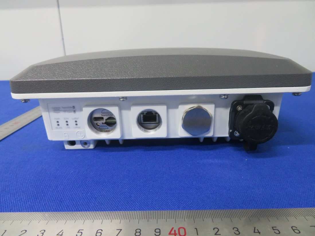
2AXA8-GBP-2007
Oct 13, 2024Mesh Pro
Equipment Class
JAB - Part 15 Class B Digital Device