2AXD8-BLUECONTROLBLE Controller
Suzhou EICCOMM Technology CO., Ltd.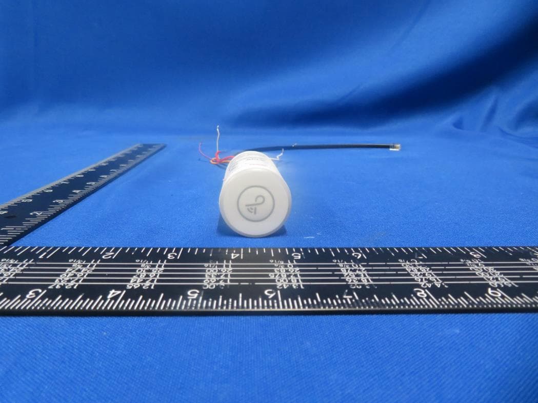
Click to zoom
Application Details
- Equipment Class
- DTS - Digital Transmission System
- Date of Grant
- Mar 07, 2021
- Application Purpose
- Original Equipment
- Date of Application
- Mar 06, 2021
- Equipment Note
- BLE Controller
- Frequency Range
- 2402.00000000 - 2480.00000000
- Country
- China
Documents & Files
Document Text
Text extracted from the exhibit documents filed with the FCC. Open a document above to read the original.
Users Manual
Welcome WE’RE HERE TO HELP: 1 (844) LIGHTCLOUD 1 (844) 544-4825 [email protected] LCBLUECONTROL/D10/W Lightcloud Blue Controller Lightcloud Blue TM Hello Lightcloud Blue is a wireless lighting control system that allows you to control RAB Lighting's various compatible devices via an APP. The Lightcloud Blue Controller is a remotely controlled switching and dimming device that can be installed into luminaires. Product Features Wireless Control & Con guration Switching up to 4.2A 0-10V Dimming Power Monitoring Patent Pending Local Control (W/O Gateway) Lightcloud Ready (W/ Gateway and Wall Bridge) Contents Lightcloud Blue Controller Wire Nuts x 4x 2 Instruction Manual NPT Nut Speci cations & Ratings PART NUMBER LCBLUECONTROL/D10/W INPUT 120/277VAC, 50/60Hz CURRENT DRAW <0.6W(Standby)–1W(Active) LOAD SWITCHING CAPACITY OPERATING TEMPERATURE: -40°C to +50°C max temp DIMENSIONS: 1.3” (D) x 2.5”(L) WIRELESS RANGE Line of Sight: 700 feet Obstructions: 70 feet RATINGS: Lightcloud Blue Controller is IP66 rated and suited for outdoor or wet locations LED/Fluorescent Incandescent 120V~/1.7A/200VA 120V~/4.2A/500W 277V~/1.5A/400VA 277V~/4.2A/1200W Setup & Installation 1 1a Tur n o power OFF OFF WARNING Find a suitable location Use these guidelines when installing devices: • If there is a clear line of sight between a Lightcloud Blue Controller and another Lightcloud Blue device they can be placed up to 500 feet apart. • If a Lightcloud Blue Controller and another Lightcloud Blue device are separated by ordinary drywall construction, try to keep them within 70 ft. of each other. • Brick, concret e and steel construction may require additional Lightcloud Blue devices to go around the obstruction. Li ghtcloud <= DRYWALL OR SIMILAR Application Add an additional Lightcloud Device to extend networ k range ar ound corners BRICK, CONCRETE, OR METAL WALL 70 ft. 2 Install the Lightcloud Blue Controller in junction box 1b Lightcloud Gateway and Wall Bridge is required to Connect with Lightcloud System Optional - What You Need for Lightcloud System The Lightcloud Blue Controller can be mounted into a junction box, with the radio module always outside any metal enclosure. I f no sensor is used then the second modular cable can be tied o and placed inside the xture or box. Lightcloud Blue Controller Light Fixture RED ORANGE BLACK WHITE PURPLE 0-10V(+) PURPLE GREY 0-10V(-) 0-10V(+) 0-10V(-) GREY GROUND GROUND BLACK LINE WHITE COMMON SHORT, GREY MODULAR CABLE SENSOR Install Luminaire 3 Install the xture with integrated Lightcloud Blue Controller to a constant power source. Do not place Lightcloud-controlled xtures down circuit from any other switching devices such as switches, sensors, or time clocks. Labeling your device When installing devices, it’s important to keep track of their Device IDs, installation locations, panel/circuit #s, dimming function, and any additional notes . To organize this infor mation, use Device Table. 4 The extra Device Identi cation stickers are provided that you can attach to your panel and one to hand o to a building manager. Device Identi cation stickers included with each device to a row, then writ e in additional infor mation, such as Zone name, P anel/Circuit Number, and whether or not a Zone uses dimming. D E V I C E I D s DEVICE 1D ZONE NAME PANEL/ CIRCUIT # DIMMING 4a Device table Setup & Installation (cont’d) Power up 5 Ver ify power and local control Con rm Status Indicator is blinking red. Con rm local control using the Device Indenti cation Button. DEVICE IDENTIFICATION BUTTON • Press once to highlight this device in the Lightcloud Application • Press twice to toggle circuit on and o • Press twice and hold to set dim level • Press and hold for 10 seconds to remove this device from a Lightcloud networ k and into pairing mode SIGNAL INDICATOR Solid GREEN when connected to your Lightcloud networ k. Blinking RED when unprovisioned. Commission your devices 6 Log on to www.lightcloud.com or call 1 (844) LIGHTCLOUD 7 Setup & Installation (cont’d) 7a Press and hold for 10 seconds to remove this device from a Lightcloud network and into pairing mode Enable Device Pairing Mode 1. Download RAB Lightcloud Application from Apple Appstore or Google Play. 2. Tap the + button in the Lightcloud App to add Lightcloud Blue Controller which is in the pairing mode. 3. Simply follow the instruction in the App to complete the commission and setup. Functionality Con guration All con guration of Lightcloud products may be perfor med using the Lightcloud web Application, or by calling RAB. Emergency default If communication is lost, the Controller may optionally fall back to a speci c state, such as turning the attached luminaire on. [ War ning: Any wires not in use must be capped o or otherwise insulated. ] WE’RE HERE TO HELP: 1 (844) LIGHTCLOUD 1 (844) 544-4825 [email protected] 7b Commission Setup & Installation (cont’d) FCC Inf or mation: This device complies with Par t 15 of the FCC Rules. Operation is subject t o the following two conditions: 1. This device may not cause harmful inter fer ence, and 2. This device must accept any inter fer ence received, including inter fer ence that may cause undesired operation. Note: This device has been tested and found to comply with the limits for Class B digital devices pursuant to Par t 15 Subpart B, of the FCC rules. These limits are designed to provide reasonable pr ot ection against harmful inter fer ence in a residential environ- ment. This equipment generates , uses, and can radiate radio fr equency energy, and if not installed and used in accordance with the instruction manual, may cause harmful inter fer ence to radio communications. However , there is no guarantee that inter- fer ence will not occur in a particular installation. If this equipment does cause harmful inter fer ence to radio or television reception, which can be deter mined by turning the equipment of and on, the user is encouraged to try and correct the inter fer …
Text truncated - open the document above for the full version.
External Photos
Report No.: 2008RSU008-UE 1 of 2 EUT Photograph (1) EUT Photo (2) EUT Photo Report No.: 2008RSU008-UE 2 of 2 (3) EUT Photo (4) EUT Photo
ID Label/Location Info
LCBLUECONTROL/W 2AXD8-BLUECONTROL LCBLUECONTROL/SS/W 2AXD8-BLUECONTROL
Internal Photos
Report No.: 2008RSU008-UE 1 of 3 EUT Photograph (1) EUT Photo (2) EUT Photo Report No.: 2008RSU008-UE 2 of 3 (3) EUT Photo (4) EUT Photo Report No.: 2008RSU008-UE 3 of 3 (5) EUT Photo
RF Exposure Info
MRT Technology (Suzhou) Co., Ltd Report No.: 2012RSU046-U3 Phone: +886-3-3288388 Report Version: V01 Web: www.mrt-cert.com Issue Date: 02-24-2021 Page Number: 1 of 8 RF Exposure Evaluation Declaration Applicant: Suzhou EICCOMM Technology CO., Ltd. Address: Room 304, Building 4, Zhuyuan Road 209, GAOXIN District, Suzhou, Jiangsu Province, China Product: BLE Controller Model No.: LCBLUECONTROL/W Brand Name: RAB FCC Classification: Digital Transmission System (DTS) Test Procedure(s): FCC Part 2.1091 Test Date: February 05, 2021 Reviewed By: Sherry Jiang Approved By: Robin Wu The test results relate only to the samples tested. The test results shown in the test report are traceable to the national/international standards through the calibration of the equipment and evaluated measurement uncertainty herein. The test report shall not be reproduced except in full without the written approval of MRT Technology (Suzhou) Co., Ltd. Report No.: 2012RSU046-U3 Page Number: 2 of 8 Revision History Report No. Version Description Issue Date Note 2012RSU046-U3 Rev. 01 Initial Report 02-24-2021 Valid Report No.: 2012RSU046-U3 Page Number: 3 of 8 CONTENTS Description Page 1. GENERAL INFORMATION ........................................................................................ 4 1.1. Applicant ................................................................................................................... 4 1.2. Manufacturer ............................................................................................................ 4 1.3. Testing Facility ......................................................................................................... 4 2. PRODUCT INFORMATION ........................................................................................ 5 2.1. Equipment Description ........................................................................................... 5 2.2. Description of Available Antennas ........................................................................ 5 3. RF Exposure Evaluation ........................................................................................... 6 3.1. Limits ......................................................................................................................... 6 3.2. Test Result of RF Exposure Evaluation ............................................................... 7 Appendix A - EUT Photograph ........................................................................................ 8 Report No.: 2012RSU046-U3 Page Number: 4 of 8 1. GENERAL INFORMATION 1.1. Applicant Suzhou EICCOMM Technology CO., Ltd. Room 304, Building 4, Zhuyuan Road 209, GAOXIN District, Suzhou, Jiangsu Province, China 1.2. Manufacturer RAB LIGHTING INC 170 Ludlow Ave,PO BOX 970,Northvale, NJ 07647-2305 USA 1.3. Testing Facility Test Site – MRT Suzhou Laboratory Laboratory Location (Suzhou – Wuzhong) D8 Building, No.2 Tian’edang Rd., Wuzhong Economic Development Zone, Suzhou, China Laboratory Location (Suzhou – SIP) 4b Building, Liando U Valley, No.200 Xingpu Rd., Shengpu Town, Suzhou Industrial Park, China Laboratory Accreditations A2LA: 3628.01 CNAS: L10551 FCC: CN1166 ISED: CN0001 VCCI: R-20025, G-20034, C-20020, T-20020 Test Site – MRT Shenzhen Laboratory Laboratory Location (Shenzhen) 1G, Building A, Junxiangda Building, Zhongshanyuan Road West, Nanshan District, Shenzhen, China Laboratory Accreditations A2LA: 3628.02 CNAS: L10551 FCC: CN1284 ISED: CN0105 Test Site – MRT Taiwan Laboratory Laboratory Location (Taiwan) No. 38, Fuxing 2 nd Rd., Guishan Dist., Taoyuan City 333, Taiwan (R.O.C.) Laboratory Accreditations TAF: L3261-190725 FCC: 291082, TW3261 ISED: TW3261 Report No.: 2012RSU046-U3 Page Number: 5 of 8 2. PRODUCT INFORMATION 2.1. Equipment Description 2.2. Description of Available Antennas Antenna Type Frequency Band (GHz) Antenna Gain (dBi) External PCB Antenna 2.4~2.5 2.00 Product Name BLE Controller Model No. LCBLUECONTROL/W Serial Model No. LCBLUECONTROL/SS/W Bluetooth Version v5.0 single mode, LE only Serial Number 20201214Sample#03 Power Supply Input :120-277Vac 50/60Hz Remark LCBLUECONTROL/SS/W has 3 more lines than LCBLUECONTROL/W, used to adjust the color of the product, the other parts are identical. Report No.: 2012RSU046-U3 Page Number: 6 of 8 3. RF Exposure Evaluation 3.1. Limits According to FCC 1.1310: The criteria listed in the following table shall be used to evaluate the environment impact of human exposure to radio frequency (RF) radiation as specified in 1.1307(b) LIMITS FOR MAXIMUM PERMISSIBLE EXPOSURE (MPE) Frequency Range (MHz) Electric Field Strength (V/m) Magnetic Field Strength (A/m) Power Density (mW/cm 2 ) Average Time (Minutes) (A) Limits for Occupational/ Control Exposures 300-1500 -- -- f/300 6 1500-100,000 -- -- 5 6 (B) Limits for General Population/ Uncontrolled Exposures 300-1500 -- -- f/1500 6 1500-100,000 -- -- 1 30 f= Frequency in MHz Calculation Formula: Pd = (Pout*G)/(4*pi*r 2 ) Where Pd = power density in mW/cm 2 Pout = output power to antenna in mW G = gain of antenna in linear scale Pi = 3.1416 r = distance between observation point and center of the radiator in cm Pd is the limit of MPE, 1mW/cm². If we know the maximum gain of the antenna and the total power input to the antenna, through the calculation, we will know the distance r where the MPE limit is reached. Report No.: 2012RSU046-U3 Page Number: 7 of 8 3.2. Test Result of RF Exposure Evaluation Product BLE Controller Test Item RF Exposure Evaluation Test Mode Frequency Band (MHz) Maximum EIRP (dBm) Power Density at R = 20 cm (mW/cm 2 ) Limit (mW/cm 2 ) BLE 2402 ~ 2480 3.85 0.0005 1 CONCLUSION: So, the safety distance is 20cm for BLE Controller installed without any other radio equipment. The End Report No.: 2012RSU046-U3 Page Number: 8 of 8 Appendix A - EUT Photograph Refer to “2012RSU046-UE” file.
Test Report
MRT Technology (Suzhou) Co., Ltd Report No.: 2012RSU046-U2 Phone: +86-512-66308358 Report Version: V01 Web: www.mrt-cert.com Issue Date: 02-22-2021 Page Number: 1 of 67 FCC ID: 2AXD8-BLUECONTROL APPLICANT: Suzhou EICCOMM Technology CO., Ltd. Application Type: Certification Product: BLE Controller Model No.: LCBLUECONTROL/W Serial Model No.: LCBLUECONTROL/SS/W Brand Name: RAB FCC Classification: Digital Transmission System (DTS) FCC Rule Part(s): Part15 Subpart C (Section 15.247) Test Procedure(s): ANSI C63.10-2013 Test Date: December 16, 2020 ~ February 05, 2021 Reviewed By: Sherry Jiang Approved By: Robin Wu MEASUREMENT REPORT FCC PART 15.247 / Bluetooth-LE The test results relate only to the samples tested. This equipment has been shown to be capable of compliance with the applicable technical standards as indicated in the measurement report and was tested in accordance with the measurement procedures specified in ANSI C63.10-2013. Test results reported herein relate only to the item(s) tested. The test report shall not be reproduced except in full without the written approval of MRT Technology (Suzhou) Co., Ltd. Report No.: 2012RSU046-U2 Page Number: 2 of 67 Revision History Report No. Version Description Issue Date Note 2012RSU046-U2 Rev. 01 Initial Report 02-22-2021 Valid Report No.: 2012RSU046-U2 Page Number: 3 of 67 CONTENTS Description Page 1. General Information ............................................................................................................... 5 1.1. Applicant ....................................................................................................................... 5 1.2. Manufacturer ................................................................................................................ 5 1.3. Testing Facility .............................................................................................................. 5 2. PRODUCT INFORMATION ..................................................................................................... 6 2.1. Feature of Equipment under Test ................................................................................. 6 2.2. Product Specification Subjective to this Report ............................................................. 6 2.3. Test Configuration ........................................................................................................ 7 2.4. Test System Details ...................................................................................................... 7 2.5. Working Frequencies for this Report ............................................................................. 8 2.6. Test Mode .................................................................................................................... 8 2.7. Duty Cycle .................................................................................................................... 9 2.8. EMI Suppression Device(s)/Modifications ..................................................................... 9 2.9. Description of Test Software ......................................................................................... 9 2.10. Test Environment Condition .......................................................................................... 9 3. ANTENNA REQUIREMENTS ................................................................................................ 10 4. TEST EQUIPMENT CALIBRATION DATE ............................................................................. 11 5. MEASUREMENT UNCERTAINTY ......................................................................................... 15 6. TEST RESULT ...................................................................................................................... 16 6.1. Summary .................................................................................................................... 16 6.2. 6dB Bandwidth Measurement ..................................................................................... 17 6.2.1. Test Limit ................................................................................................................ 17 6.2.2. Test Procedure used ............................................................................................... 17 6.2.3. Test Setting ............................................................................................................. 17 6.2.4. Test Setup ............................................................................................................... 17 6.2.5. Test Result .............................................................................................................. 18 6.3. Output Power Measurement ....................................................................................... 20 6.3.1. Test Limit ................................................................................................................ 20 6.3.2. Test Procedure Used .............................................................................................. 20 6.3.3. Test Setting ............................................................................................................. 20 6.3.4. Test Setup ............................................................................................................... 21 6.3.5. Test Result of Output Power ................................................................................... 22 6.4. Power Spectral Density Measurement ........................................................................ 23 6.4.1. Test Limit ................................................................................................................ 23 Report No.: 2012RSU046-U2 Page Number: 4 of 67 6.4.2. Test Procedure Used .............................................................................................. 23 6.4.3. Test Setting ...................................................................................…
Text truncated - open the document above for the full version.
Test Setup Photos
Report No.: 2008RSU008-UT 1 of 2 FCC PART 15C Test Setup Photo Description: Radiated Spurious Emission Test Setup for 30MHz ~ 1GHz Description: Radiated Spurious Emission Test Setup for 1GHz ~ 18GHz Report No.: 2008RSU008-UT 2 of 2 Description: Front view of Conducted Emission Test Setup Description: Back view of Conducted Emission Test Setup
Contact Information
Applicant
JINGJING WU
Technical Contact
MRT Technology (Suzhou) Co., LtdRobin Wu
[email protected]86-512-66308358
D8 Building, Youxin Industrial Park, · Suzhou · China
Non-Technical Contact
MRT Technology (Suzhou) Co., LtdRobin Wu
[email protected]86-512-66308358
Test Firm
MRT Technology (Suzhou) Co., Ltd.Mr. Marlin Chen
[email protected]+86-512-66308358
Technical Specifications
| # | Rule Parts | Frequency Range | Power Output |
|---|---|---|---|
| 1 | 15C | 2.40 GHz - 2.48 GHz | 1.53 mW |
Other Applications from Suzhou EICCOMM Technology CO., Ltd.
2AXD8-BLET8WT
Sep 23, 2022LED tube
Equipment Class
DTS - Digital Transmission System
2AXD8-BLEFILAMENT
Mar 22, 2022Lightcloud Blue
Equipment Class
DTS - Digital Transmission System
2AXD8-LCBLUEREMOTE
Jul 28, 2021RAB Bluetooth Remote Control
Equipment Class
DTS - Digital Transmission System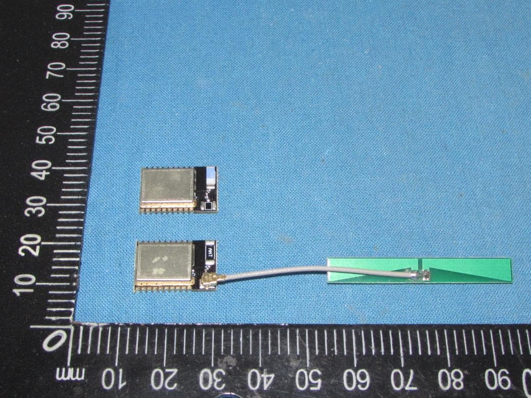
2AXD8TURING
Sep 15, 2020Turing Bluetooth module
Equipment Class
DTS - Digital Transmission System