A29-TELACWCAREMOTE CONTROL FOR AIRCHOC WIRELESS APPLICATION
Standard Industrie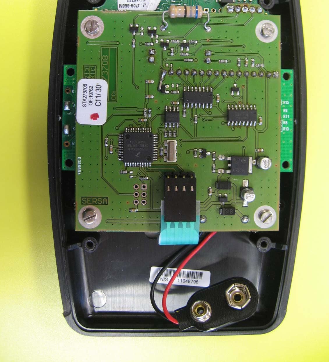
Click to zoom
Application Details
- Equipment Class
- DTS - Digital Transmission System
- Date of Grant
- Jan 21, 2014
- Application Purpose
- Original Equipment
- Date of Application
- Jan 21, 2014
- Equipment Note
- REMOTE CONTROL FOR AIRCHOC WIRELESS APPLICATION
- Frequency Range
- 915.00000000 - 915.00000000
- Company
- Standard Industrie
- Country
- France
Documents & Files
Document Text
Text extracted from the exhibit documents filed with the FCC. Open a document above to read the original.
Users Manual
NOTTELACW-US.doc 1 December 6th, 2012 Produced on: December 6th, 2012 By: DESIGN OFFICE Checked on: By: BOISLEUX.M Signature: USER MANUAL Revision Level: F1 NOTTELACW-US Date: December 6th, 2012 HEAD OFFICE- Standard Industrie : 139-141 rue du Luxembourg-BP50207 59054 ROUBAIX CEDEX 1- FRANCE +33 (0)3 20 28 32 32 / @ : [email protected] NOTTELACW-US.doc 2 December 6th, 2012 CONTENTS 1 Principle of Airchoc Wireless page 4 2 Principle of remote control page 4 3 Remote Control Unit Presentation page 4 3-1 General Characteristics page 4 4 Installing the Battery and Starting-up page 5 5 Principle page 6 6 Remote Control Unit Indications on Start-up page 6 7 Menu Operation page 6 8 Manual Airchoc Firing page 7 9 Airchoc Consultation page 8 10 Airchoc Isolation page 8 11 Access Code page 9 12 Language Selection page 9 13 Signal Level page 9 14 General Information page 10 14-1 Instructions page 10 14-2 Remote Control Unit Auto Shut-off page 10 14-3 Additional Information page 10 14-4 Using the Battery page 10 14-5 Recycling the Battery and the Remote Control Unit page 10 14-6 Hazard Area page 10 14-7 Warranty page 10 14-8 After Sales Service page 10 NOTTELACW-US.doc 3 December 6th, 2012 1- Principle of Airchoc Wireless 2- Principle of remote control NOTTELACW-US.doc 4 December 6th, 2012 3- REMOTE CONTROL UNIT PRESENTATION 3-1. General Characteristics 3-11. Electrical Characteristics - Battery supply voltage: 9V dc, type 6LF22 or 6LR61, included, - Standard Industrie reference: CSMELE9V Attention, use only alkaline in remote control. 3-12 Explanation of the symbol on the label : Direct current This device complies with Part 15 of the FCC Rules. Operation is subject to the following two conditions: (1) this device may not cause harmful interference, and (2) this device must accept any interference received, including interference that may cause undesired operation. 3-13. Environmental characteristics: Attention : it is forbidden to clean the remote control to the high-pressure water. The protection is impaired if equipment is used in a manner not specified by the manufacturer. 3-14. Additional Exterior Characteristics - Operator interface: - 2-line 16-character LCD display with low back lighting - 3-key keyboard - Indicator LED: Green, system (system operational) Red, fault (fault detected) - Service temperature: - Humidity : - Max altitude - Pollution degree Minimum: -10°C Maximum: +70°C no more than 80% e.g up to 2000 m 3 Display Keyboard LED indicator s Enter On / Off Button 9v battery housing Belt clip NOTTELACW-US.doc 5 December 6th, 2012 4- INSTALLING THE BATTERY AND STARTING-UP Remove the battery compartment cover by lightly pressing with the end of your finger. Connect the 9V battery to the connector respecting the polarity. To close the battery compartment cover – follow the slides – lightly press the cover into place with the end of your finger Place the battery in its compartment Press the On / Off button for at least 3 s to start NOTTELACW-US.doc 6 December 6th, 2012 5-PRINCIPLE: The wireless remote control unit communicates with receiver units on the Airchocs through the wireless cabinet. Upon start-up, the remote control unit establishes communications with the cabinet before becoming functional. If the connection with the cabinet cannot be established, a communications fault has occurred and the unit cannot function. 6- REMOTE CONTROL UNIT INDICATIONS ON START-UP Ensure you are within range of the antenna or router if there is one. When the remote control unit powers up, the display indicates the software version. Functions may be accessed using the ▲/▼ keys and the ENTER key. Generally: - The ▲ ▼ keys are used for selecting a line or moving left and right - The ENTER- ON/OFF key is used for: validating data input (short press <1 s) start-up / shut-off (press > 3 s) At any time by pressing ▲ and ENTER you will be returned to the menu 7- MENU OPERATION The various menus accessible with an access code are in orange (see page 8) - Manual firing: this menu is used to fire a previously selected Airchoc. - AC consultation: this menu is used to check whether the Airchocs are active or inactive. - AC isolation: this menu is used to activate or deactivate Airchocs for safety during maintenance. - Access code: this menu is used to record and modify the access code. - Language selection: this menu is used to select the display language. English by default - Signal level: this menu is used to verify the communications level, expressed as a % from your location with the remote control to the cabinet antenna module. If you have placed routers, you may do the same to verify communications between your location with the remote control and a router in range. This is for informational purposes only and may vary subject to disturbances. Soft versio n : 1.04 S h o oting munual C o n sultation AC C o n signment AC A c c ess code L a n guage setting S i g nal Level Nos i g n a l WIRELESS REMOTE CONTROL UNIT START-UP Press the ON/OFF button for 3 s The green LED comes on Display If the Wireless cabinet is not on Display AC Airchoc ( Visible lines Grey lines made visible by scrolling NOTTELACW-US.doc 7 December 6th, 2012 8- MANUAL AIRCHOC FIRING MENU ACCESSED BY ACCESS CODE After entering the access code, the remote control unit connects to the cabinet (to view the accessible Airchocs). If communications are not good, the display will remain locked on: Search Airchoc CONNECTION ESTABLISHED WITH THE CABINET When the connection is established, the display indicates the Airchocs registered with the cabinet: - - > 0 01 XXXX 0 02 XXXX S h o o ting forXXXX Q u i t Valid S h o o ting forXXXX Q u i t Valid If the fire order is given, the display changes to: S h o o ting forXXXX I n progress S h o o ting forXXXX S uccessful If, in the next 10 seconds, firing is not performed communication between the remote control and the cabinet reception is not good. The red LED comes on and the display indicates …
Text truncated - open the document above for the full version.
Cover Letter(s)
S.A.S. au capital de 1 237 600 € - R.C. ROUBAIX 312 479 769 - SIRET 312 479 769 00035 - APE 2899B - TVA FR 853 12479769 Siège social et usines 139-141, rue du Luxembourg Tél. : +33 (0)3 20 28 32 32 CS 50207 Fax. : +33 (0)3 20 68 51 16 59054 ROUBAIX Cedex 1 E-mail : [email protected] France www.standard-industrie.com Attn: TIMCO Engineering Inc. Authority to Act as Agent On our behalf, I appoint M. Loïc BERTHAUD from Emitech Angers - site de Beaucouzé, 15 rue de la Claie ZI Angers/Beaucouzé, 49070 Beaucouzé FRANCE, to act as our agent in the preparation of this application for equipment certification. I certify that submitted documents properly describe the device or system for which equipment certification is sought. I also certify that each unit manufactured, imported or marketed, as defined in the Federal Communications Commission’s regulations will have affixed to it a label identical to that submitted for approval with this application. For instances where our authorized agent signs the application for certification on our behalf, I acknowledge that all responsibility for complying with the terms and conditions for certification, still resides with Standard Industrie, 139-141 rue du Luxembourg, BP 50207, 59054 Roubaix FRANCE . This authorization is valid until further written notice from Standard Industrie. January the 21 st , 2013 By DUHAUTOIS Jean-François – Technical Manager Signature
Cover Letter(s)
S.A.S. au capital de 1 237 600 € - R.C. ROUBAIX 312 479 769 - SIRET 312 479 769 00035 - APE 2899B - TVA FR 853 12479769 Siège social et usines 139-141, rue du Luxembourg Tél. : +33 (0)3 20 28 32 32 CS 50207 Fax. : +33 (0)3 20 68 51 16 59054 ROUBAIX Cedex 1 E-mail : [email protected] France www.standard-industrie.com Federal Communications Commission Authorization and Evaluation Division Confidentiality Request regarding application for certification of FCC ID: A29- TELACWCA. Pursuant to Sections 0.457 and 0.459 of the Commission’s Rules, we hereby request confidential treatment of information accompanying this application as outlined below: Exhibit Type File Name Operational description TELACWCA-OpDes_EN.pdf Block diagram TELACWCA-BlkDia.pdf Electrical schematics TELACWCA-Schem.pdf Parts list TELACWCA-PartsLst.pdf The above materials contain trade secrets and proprietary information not customarily released to the public. The public disclosure of these materials may be harmful to the applicant and provide unjustified benefits to its competitors. The applicant understands that pursuant to Section 0.457 of the Rules, disclosure of this application and all accompanying documentation will not be made before the date of the Grant for this application. Sincerely, By DUHAUTOIS Jean-François – Technical Manager Signature
Cover Letter(s)
Z.I. Angers - Beaucouzé - 15, rue de la Claie - 49070 BEAUCOUZE - Siret : 344 545 645 00055 Tél. : 02 41 73 26 27 - Fax : 02 41 73 26 40 - E-mail : [email protected] - URL : www.emitech.fr Siège Social : 3, rue des Coudriers - CAP 78 - ZA de l’Observatoire - 78180 MONTIGNY LE BX S.A. au capital de 1 560 000 € - R.C.S. VERSAILLES 344 545 645 - APE 7112B Siège Social : Emitech ‐ 3, rue des Coudriers ‐ Z.A. de l’Observatoire ‐78180 MONTIGNY LE BX ‐France Siret : 344 545 645 00022 ‐ Tél. : 33 (0)1 30 57 55 55 ‐ Fax : 33 (0)1 30 43 74 48 ‐ E‐mail : [email protected] ‐ URL : www.emitech.fr S.A. au capital de 1 560 000 € ‐ R.C.S. VERSAILLES 344 545 645 ‐ APE 7112B Centre d’ANGERS 15 Rue de la Claie 49070 BEAUCOUZE FRANCE Tél : +33 241 732 627 Attention : Timco Engineering, Inc. Airchoc remote control Model : TELACWCA FCC ID : A29- TELACWCA IC : 10022A- TELACWCA I, Jean-François DUHAUTOIS, Technical Manager from Standard Industrie, 139-141 rue du Luxembourg BP50207 59054 Roubaix FRANCE, declare that the device presented to certification has not been amended since December 09, 2011. Produced devices remain electrically identical to tested sample and data submitted reflects present operation of the device. As stated in test report, the device has been verified to comply with KDB 558074 for a DTS device. The test report has been revalidated to ensure compliance with the latest FCC Rules. - On behalf of Mr. Jean-François DUHAUTOIS – Beaucouzé - January 20, 2014 Loïc BERTHAUD International & Certification Manager
Test Report
Z.I. Angers - Beaucouzé - 15, rue de la Claie - 49070 BEAUCOUZE - Siret : 344 545 645 00055 Tél. : 02 41 73 26 27 - Fax : 02 41 73 26 40 - E-mail : [email protected] - URL : www.emitech.fr Siège Social : 3, rue des Coudriers - CAP 78 - ZA de l’Observatoire - 78180 MONTIGNY LE BX S.A. au capital de 1 560 000 € - R.C.S. VERSAILLES 344 545 645 - APE 7112B R051-24-11-105713-1/A Ed. 0 RADIO test report according to standard: CFR 47- FCC Part 15 Equipment under test: ZIGBIT 900 REMOTE CONTROL Model: TELACWCA FCC ID: A29-TELACWCA Company: STANDARD INDUSTRIE DISTRIBUTION: Mr DUHAUTOIS Company: STANDARD INDUSTRIE Number of pages: 24 including 5 annexes Technical Verification Ed. Date ModifiedWritten by Quality Approval pages Name Visa Name Visa 0 16-Jul-12 Creation M. DUMESNIL Duplication of this document is only permitted for an integral photographic facsimile. It includes the number of pages referenced here above. This document is the result of testing a specimen or a sample of the product submitted. It does not imply an assessment of the conformity of the whole manufactured products of the tested sample. R051-24-11-105713-1/A Ed. 0 PAGE 2 R051-24-11-105713-1-A-SG PRODUCT: Zigbit 900 remote control Reference / model : TELACWCA Serial number : Not communicated MANUFACTURER: STANDARD INDUSTRIE COMPANY SUBMITTING THE PRODUCT: Company : STANDARD INDUSTRIE Address : 139-141 rue du Luxembourg BP 50207 59054 ROUBAIX Cedex 01 FRANCE Responsible : Mr DUHAUTOIS TECHNICAL SUPPORT: Company : SERSA Address : 264 avenue de la Mauldre 78680 EPONE FRANCE Responsible : Mr OBERT DATE(S) OF TEST: 25 and 30 November 2011 1, 2 and 9 December 2011 TESTING LOCATION: EMITECH ATLANTIQUE laboratory at JUIGNE SUR LOIRE (49) FRANCE EMITECH ATLANTIQUE open area test site in JUIGNE SUR LOIRE (49) FRANCE FCC Registration Number: 90469 TESTED BY: M. DUMESNIL R051-24-11-105713-1/A Ed. 0 PAGE 3 R051-24-11-105713-1-A-SG CONTENTS TITLE PAGE 1. INTRODUCTION.......................................................................................................................... 4 2. PRODUCT DESCRIPTION .........................................................................................................4 3. NORMATIVE REFERENCE....................................................................................................... 4 4. TEST METHODOLOGY .............................................................................................................5 5. TEST EQUIPMENT CALIBRATION DATES.......................................................................... 5 6. TESTS AND CONCLUSIONS ..................................................................................................... 6 7. RADIATED EMISSION LIMITS ................................................................................................ 8 8. ADDITIONAL PROVISIONS TO THE GENERAL RADIATED EMISSION LIMITATIONS ................................................................................................................................ 10 9. MAXIMUM PEAK OUTPUT POWER .................................................................................... 12 10. INTENTIONAL RADIATOR .................................................................................................. 14 11. PEAK POWER DENSITY........................................................................................................ 16 ANNEX 1: 6 dB BANDWIDTH...................................................................................................... 18 ANNEX 2: BANDE EDGE.............................................................................................................. 19 ANNEX 3: 20 dB BANDWIDTH.................................................................................................... 20 ANNEX 4: PHOTOS OF THE EQUIPMENT UNDER TEST ................................................... 21 ANNEX 5: TEST SET UP AND OPEN AREA TEST SITE ....................................................... 24 R051-24-11-105713-1/A Ed. 0 PAGE 4 R051-24-11-105713-1-A-SG 1. INTRODUCTION This document presents the result of RADIO test carried out on the following equipment : Zigbit 900 remote control − Model: TELACWCA in accordance with normative reference. 2. PRODUCT DESCRIPTION ITU Emission code: 1M41G1D Class: B (residential environment) Utilization: remote control used to manually trigger airchocs Antenna type and gain: dedicated integral antenna, unknown gain Operating frequency range: 915 MHz Number of channels: 1 Channel spacing: not concerned Frequency generation: quartz 8 MHz and phase-locked loop Modulation: BPSK (Binary Phase Shifting Key) Power source: 1 x 6LR61 (battery 9V) Power level, frequency range and channels characteristics are not user adjustable. The details pictures of the product and the circuit boards are joined with this file. 3. NORMATIVE REFERENCE The standards and testing methods related throughout this report are those listed below. They are applied on the whole test report even though the extensions (version, date and amendment) are not repeated. CFR 47 - FCC Part 15 (2011) Radio Frequency Devices ANSI C63.4 (2003) Methods of Measurement of Radio-Noise Emissions from Low-voltage Electrical and Electronics Equipment in the range of 9 kHz to 40 GHz. 558074 D01 DTS Meas guidance v01 Guidance for performing Compliance Measurement on Digital Transmission Systems (DTS) Operating under §15.247 R051-24-11-105713-1/A Ed. 0 PAGE 5 R051-24-11-105713-1-A-SG 4. TEST METHODOLOGY Radio performance tests procedures given in part 15: Subpart B –Unintentional Radiators Paragraph 107: Conducted limits Paragraph 109: Radiated emission limits Paragraph 111: Antenna power conduction limits for receivers Subpart C – Intentional Radiators Paragraph 203: Antenna requirement Paragraph 205: Restricted bands of operation Paragraph 207: Conducted limits Paragraph 209: Radiated emission limits; general requirements Paragraph 212: Modular transmitter Paragraph 215: Additio…
Text truncated - open the document above for the full version.
Test Setup Photos
OPEN AREA TEST
Contact Information
Applicant
Jean Francois Jean Francois DUHAUTOIS
Test Firm
EMITECH ANGERSOlivier ROY
Technical Specifications
| # | Rule Parts | Frequency Range | Power Output |
|---|---|---|---|
| 1 | 15C | 915 MHz - 915 MHz | 200.00 µW |
Other Applications from Standard Industrie
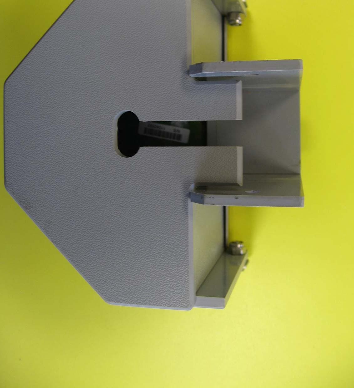
A29-REWCASEV
Jan 21, 2014RECEIVER FOR AIRCHOC WIRELESS APPLICATION
Equipment Class
DTS - Digital Transmission System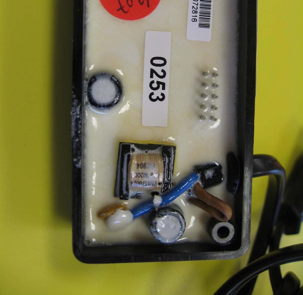
A29-COFROUTCA
Jan 19, 2014ROUTER FOR AIRCHOC WIRELESS APPLICATION
Equipment Class
DTS - Digital Transmission System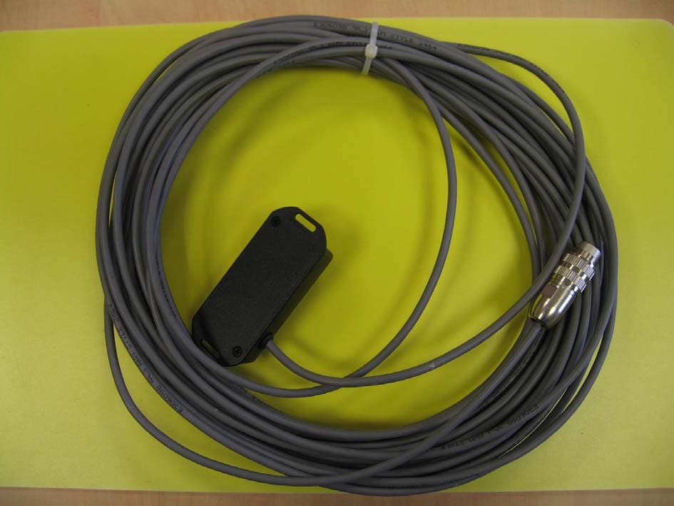
A29-COFACWCA
Jan 16, 2014CONTROL PANEL FOR AIRCHOC WIRELESS APPLICATION
Equipment Class
DTS - Digital Transmission System