A2HRCT6077W27 inch Tablet
Alco Electronics Ltd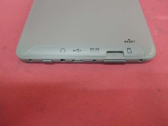
Click to zoom
Application Details
- Equipment Class
- DXX - Part 15 Low Power Communication Device Transmitter
- Date of Grant
- Sep 01, 2013
- Application Purpose
- Original Equipment
- Date of Application
- Sep 01, 2013
- Equipment Note
- 7 inch Tablet
- Frequency Range
- 2412.00000000 - 2462.00000000
- Company
- Alco Electronics Ltd
- Country
- Hong Kong
Documents & Files
Document Text
Text extracted from the exhibit documents filed with the FCC. Open a document above to read the original.
Users Manual
RCT6077W2 User Manual It's important to read this instruction prior to using your new product for the first time. 7” Tablet Scan for more user manual details SafeTy PReCaUTionS EN - 1 RCT6077W2 Equipment tested for compliance as a complete unit This device complies with Part 15 of the FCC Rules. Operation is subject to the following two conditions: (1) This device may not cause harmful interference, and (2) this device must accept any interference received, including interference that may cause undesired operation. This equipment has been tested and found to comply with the limits for a Class B digital device, pursuant to Part 15 of FCC Rules. These limits are designed to provide reasonable protection against harmful interference in a residential installation. This equipment generates, uses, and can radiate radio frequency energy and, if not installed and used in accordance with the instructions, may cause harmful interference to radio communications. However, there is no guarantee that interference will not occur in a particular installation. If this equipment does cause harmful interference to radio or television reception, which can be determined by turning the equipment off and on, the user is encouraged to try to correct the interference by one or more of the following measures: • Reorient or relocate the receiving antenna. • Increase the separation between the equipment and receiver. • Connect the equipment into an outlet on a circuit different from that to which the receiver is connected. • Consult the dealer or an experienced radio/TV technician for help. Warning: Changes or modifications not expressly approved by the party responsible for compliance (MLB International Inc., P.O. Box 1535, Buffalo, NY 14226, Tel: 516- 236-4556) could void the user’s authority to operate the equipment. Caution: Use of controls or adjustments or performance of procedures other than those specified may result in hazardous radiation exposure. Warning: The AC/DC adaptor is used as disconnect device. The AC/ DC adaptor of apparatus should not be obstructed OR should be easily accessed during intended used. To be completely disconnect the power input, the AC/DC adaptor of apparatus shall be disconnected from the mains. Trademark information Google Play, YouTube and other marks are trademarks of Google Inc. The Android robot is reproduced or modified from work created and shared by Google and used according to terms described in the Creative Commons 3.0 Attribution License. The Wi-Fi CERTIFIED Logo is a certification mark of the Wi-Fi Alliance. The Wi-Fi Protected Setup Mark is a mark of the Wi-Fi Alliance. for your Safety The AC power plug is polarized and only fits into AC power outlets one way. If the plug won’t go into the outlet completely, turn the plug over and try to insert it the other way. If it still won’t fit, contact a qualified electrician to change the outlet, or use a different one. Do not attempt to bypass this safety feature. Service information This product should be serviced only by those specially trained in appropriate servicing techniques. For instructions on how to obtain service, refer to the warranty included in this guide. Some of the following information may not apply to your particular product; however, as with any electronic product, precautions should be observed during handling and use. • Read these instructions. • Keep these instructions. • Heed all warnings. • Follow all instructions. • Do not use this apparatus near water. • Clean only with dry cloth. • Do not block any ventilation openings. Install in accordance with the manufacturer’s instructions. • Do not install near any heat sources such as radiators, heat registers, stoves, or other apparatus (including amplifiers) that produce heat. • The AC power plug is polarized and only fits into AC power outlets one way. If the plug won’t go into the outlet completely, turn the plug over and try to insert it the other way. If it still won’t fit, contact a qualified electrician to change the outlet, or use a different one. Do not attempt to bypass this safety feature. • Protect the power cord from being walked on or pinched par ticularly at plugs, convenience receptacles, and the point where they exit from the apparatus. • Only use attachments / accessories specified by the manufacturer. • Unplug this apparatus during lightning storms or when unused for long periods of time. • Refer all servicing to qualified service personnel. Servicing is required when the apparatus has been damaged in any way, such as power-supply cord or plug is damaged, liquid has been spilled or objects have fallen into the apparatus, the apparatus has been exposed to rain or moisture, does not operate normally, or has been dropped. aDDiTionaL SafeTy infoRMaTion • The AC/DC adaptor and apparatus shall not be exposed to dripping or splashing and no objects filled with liquids, such as vases, shall be placed on the apparatus. • Always leave sufficient space around the product for ventilation. Do not place product in or on a bed, rug, in a bookcase or cabinet that may prevent air flow through vent openings. • Do not place lighted candles, cigarettes, cigars, etc. on the product. • Connect power cord only to AC power source as marked on the product. • Care should be taken so that objects do not fall into the product. • D o n o t a t t e m p t t o d i s a s s e m bl e t h e c a b i n e t . T h i s p r o d u c t d o e s n o t c o n t a i n customer serviceable components. • To reduce the risk of fire or electric shock, do not expose this apparatus to rain or moisture. • Do not play your headset at high volume. Hearing experts warn against extended high-volume play. iMPoRTanT SafeTy inSTRUCTionS PLEASE READ AND SAVE THIS FOR FUTURE REFERENCE EN - 2 Switch on/Unlock Switch on and unlock: When the device is in the OFF mode, press and hold “POwER” key to enter the startup screen, then the screen is in locked mode. And press and pull the icon to the unlocked pos…
Text truncated - open the document above for the full version.
Users Manual
CT9077W2 User Manual It's important to read this instruction prior to using your new product for the first time. 7” Tablet Scan for more user manual details SafeTy PReCaUTionS EN - 1 CT9077W2 Equipment tested for compliance as a complete unit This device complies with Part 15 of the FCC Rules. Operation is subject to the following two conditions: (1) This device may not cause harmful interference, and (2) this device must accept any interference received, including interference that may cause undesired operation. This equipment has been tested and found to comply with the limits for a Class B digital device, pursuant to Part 15 of FCC Rules. These limits are designed to provide reasonable protection against harmful interference in a residential installation. This equipment generates, uses, and can radiate radio frequency energy and, if not installed and used in accordance with the instructions, may cause harmful interference to radio communications. However, there is no guarantee that interference will not occur in a particular installation. If this equipment does cause harmful interference to radio or television reception, which can be determined by turning the equipment off and on, the user is encouraged to try to correct the interference by one or more of the following measures: • Reorient or relocate the receiving antenna. • Increase the separation between the equipment and receiver. • Connect the equipment into an outlet on a circuit different from that to which the receiver is connected. • Consult the dealer or an experienced radio/TV technician for help. Warning: Changes or modifications not expressly approved by the party responsible for compliance (MLB International Inc., P.O. Box 1535, Buffalo, NY 14226, Tel: 516- 236-4556) could void the user’s authority to operate the equipment. Caution: Use of controls or adjustments or performance of procedures other than those specified may result in hazardous radiation exposure. Warning: The AC/DC adaptor is used as disconnect device. The AC/ DC adaptor of apparatus should not be obstructed OR should be easily accessed during intended used. To be completely disconnect the power input, the AC/DC adaptor of apparatus shall be disconnected from the mains. Trademark information Google Play, YouTube and other marks are trademarks of Google Inc. The Android robot is reproduced or modified from work created and shared by Google and used according to terms described in the Creative Commons 3.0 Attribution License. The Wi-Fi CERTIFIED Logo is a certification mark of the Wi-Fi Alliance. The Wi-Fi Protected Setup Mark is a mark of the Wi-Fi Alliance. for your Safety The AC power plug is polarized and only fits into AC power outlets one way. If the plug won’t go into the outlet completely, turn the plug over and try to insert it the other way. If it still won’t fit, contact a qualified electrician to change the outlet, or use a different one. Do not attempt to bypass this safety feature. Service information This product should be serviced only by those specially trained in appropriate servicing techniques. For instructions on how to obtain service, refer to the warranty included in this guide. Some of the following information may not apply to your particular product; however, as with any electronic product, precautions should be observed during handling and use. • Read these instructions. • Keep these instructions. • Heed all warnings. • Follow all instructions. • Do not use this apparatus near water. • Clean only with dry cloth. • Do not block any ventilation openings. Install in accordance with the manufacturer’s instructions. • Do not install near any heat sources such as radiators, heat registers, stoves, or other apparatus (including amplifiers) that produce heat. • The AC power plug is polarized and only fits into AC power outlets one way. If the plug won’t go into the outlet completely, turn the plug over and try to insert it the other way. If it still won’t fit, contact a qualified electrician to change the outlet, or use a different one. Do not attempt to bypass this safety feature. • Protect the power cord from being walked on or pinched par ticularly at plugs, convenience receptacles, and the point where they exit from the apparatus. • Only use attachments / accessories specified by the manufacturer. • Unplug this apparatus during lightning storms or when unused for long periods of time. • Refer all servicing to qualified service personnel. Servicing is required when the apparatus has been damaged in any way, such as power-supply cord or plug is damaged, liquid has been spilled or objects have fallen into the apparatus, the apparatus has been exposed to rain or moisture, does not operate normally, or has been dropped. aDDiTionaL SafeTy infoRMaTion • The AC/DC adaptor and apparatus shall not be exposed to dripping or splashing and no objects filled with liquids, such as vases, shall be placed on the apparatus. • Always leave sufficient space around the product for ventilation. Do not place product in or on a bed, rug, in a bookcase or cabinet that may prevent air flow through vent openings. • Do not place lighted candles, cigarettes, cigars, etc. on the product. • Connect power cord only to AC power source as marked on the product. • Care should be taken so that objects do not fall into the product. • D o n o t a t t e m p t t o d i s a s s e m bl e t h e c a b i n e t . T h i s p r o d u c t d o e s n o t c o n t a i n customer serviceable components. • To reduce the risk of fire or electric shock, do not expose this apparatus to rain or moisture. • Do not play your headset at high volume. Hearing experts warn against extended high-volume play. iMPoRTanT SafeTy inSTRUCTionS PLEASE READ AND SAVE THIS FOR FUTURE REFERENCE EN - 2 Switch on/Unlock Switch on and unlock: When the device is in the OFF mode, press and hold “POwER” key to enter the startup screen, then the screen is in locked mode. And press and pull the icon to the unlocked posit…
Text truncated - open the document above for the full version.
Block Diagram
55 44 33 22 11 D D C C B B A A REV: Create Date: Title:File: Page Num: Page Total: Modify Date: Block Diagram Saturday, October 23, 2010Wednesday, June 19, 2013 16 3 1.0 REV: Create Date: Title:File: Page Num: Page Total: Modify Date: Block Diagram Saturday, October 23, 2010Wednesday, June 19, 2013 16 3 1.0 REV: Create Date: Title:File: Page Num: Page Total: Modify Date: Block Diagram Saturday, October 23, 2010Wednesday, June 19, 2013 16 3 1.0 2928 PWR UART2I2C2 I2S LCDCRGB666 NAND FLASHor iNAND >=1GB DDR3 *4256M*8Bit RK2928G OSC 24M USBOTG iNAND RESET USBHOST NAND FLASH PMIC DDRInterface SDIO USB HOST RBG PANELTOUCH PANEL I2C1 I2C DEVICEDEBUG I2C0 RESET KEY BOARD GPIO&SAR_ADC FRONT CAMERAREAR CAMERA CIF LVDS PANEL CODEC SPEAKER 3.7V BATTERY 1-Cell Li+ ActivePath Battery Charger PWR ON RTC HPhone OUTMIC 24MHz GPS SPI WIFI&BT MODULE UART1SDMMC1 DC JACK Low Voltage DET 5V BOOST HDMI HDMI VIB ALCO ELECTRONICS LIMITED CT9077W2 RTL8188EUS Datasheet Single-Chip IEEE 802.11b/g/n 1T1R WLAN Controller with USB Interface 5 Track ID: JATR-2265-11 Rev. 0.3 3. Application Diagram 3.1. Single-Band 11n (1x1) Solution with Single Antenna Antenna A . PA Receiver RX I/Q DAC ADC SWR/LDO Regulators 40 MHz Crystal MAC Configuration Control and Memory Ext Interface Baseband (PHY) USB2.0 Host Interface 3.3V TX I/Q 2.4 GHz Transmitter NV Memory RTL8188EUS Balun/ Filter Circuit matching Figure 1. Single-Band 11n (1x1) Solution
External Photos
INTERTEK TESTING SERVICE Report No: 13070962HKG-001 FCC ID: A2HRCT6077W2 IC: 9903A-RCT6077W2 Equipment Photographs Model : CT9077W2 (External) INTERTEK TESTING SERVICE Report No: 13070962HKG-001 FCC ID: A2HRCT6077W2 IC: 9903A-RCT6077W2 Equipment Photographs Model : CT9077W2 (External)
Internal Photos
INTERTEK TESTING SERVICE Report No: 13070962HKG-001 FCC ID: A2HRCT6077W2 IC: 9903A-RCT6077W2 Equipment Photographs Model: CT9077W2 (Internal) INTERTEK TESTING SERVICE Report No: 13070962HKG-001 FCC ID: A2HRCT6077W2 IC: 9903A-RCT6077W2 Equipment Photographs Model: CT9077W2 (Internal) INTERTEK TESTING SERVICE Report No: 13070962HKG-001 FCC ID: A2HRCT6077W2 IC: 9903A-RCT6077W2 Equipment Photographs Model: CT9077W2 (Internal) INTERTEK TESTING SERVICE Report No: 13070962HKG-001 FCC ID: A2HRCT6077W2 IC: 9903A-RCT6077W2 Equipment Photographs Model: CT9077W2 (Internal) INTERTEK TESTING SERVICE Report No: 13070962HKG-001 FCC ID: A2HRCT6077W2 IC: 9903A-RCT6077W2 Equipment Photographs Model: CT9077W2 (Internal) INTERTEK TESTING SERVICE Report No: 13070962HKG-001 FCC ID: A2HRCT6077W2 IC: 9903A-RCT6077W2 Equipment Photographs Model: CT9077W2 (Internal)
Operational Description
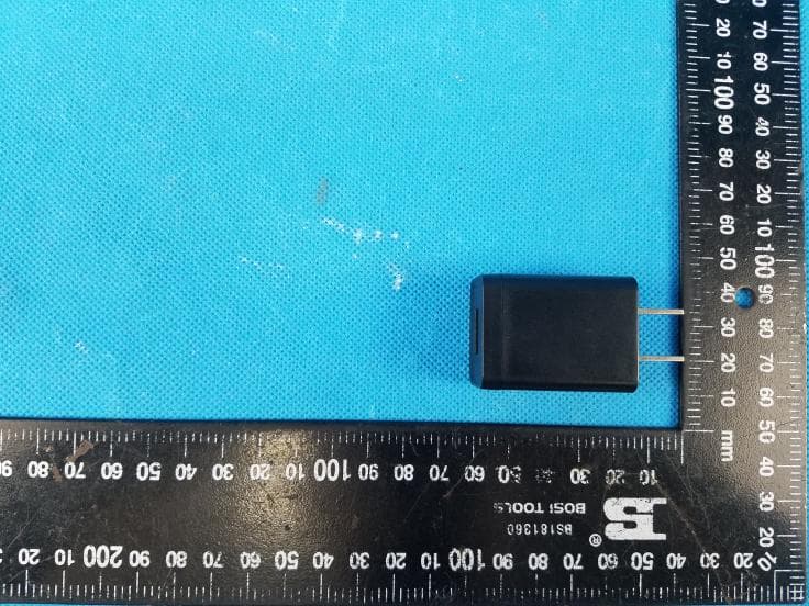
Technical Description: The Equipment Under Test (EUT) is a 7-inch Tablet with Android Operating System. The EUT equipped with a 7-inch LCD display (with touch screen), camera, USB, SD interface, loudspeaker and headphone output. The EUT contains a WiFi module complying with IEEE 802.11b/g/n(HT20)/n(HT40) standards that operating in 2.4GHz ISM frequency band (2400MHz – 2483.5MHz). The EUT is powered by an external AC/DC adaptor with 5VDC output. The adaptor accepts 100-240VAC. The applicant declared that the EUT does not contain Bluetooth RF module. An internal, integral antenna has been used. 1. WiFi module (CP318) CP318 is a WLAN USB module which fully supports the features and functional compliance of IEEE 802.11b/g/n(HT20)/n(HT40) standards. This module operates in 2.4GHz frequency bands. CP318 consists of: 1) U6 (RTL8188CUS) is a single-chip IEEE802.11b/g/n 1T1R WLAN controller with PCI (USB) interface. XTAL1 is 40MHz (crystal) clock for U6. 2. Main Processor Portion 1) U1 (RK2928G) is main p rocessor. 2) Y1 is 24MHz crystal oscillator for U1. 3. Memory Portion 1) U14 and U15 (H5TQ4G63MFR) are 4Gbit DDR3 memories. 2) U5 (TC58TEG5DCJTA00) is 4GB flash memory. Channel Occupation of CP318 WiFi Module in 802.11b/g/n standard Channel (b/g/n20) Frequency (MHz) 1 2412 2 2417 3 2422 4 2427 5 2432 6 2437 7 2442 8 2447 9 2452 10 2457 11 2462 n20 = 802.11n HT20 (20MHz Bandwidth) Channel (n40) Frequency (MHz) 1 N/A 2 N/A 3 2422 4 2427 5 2432 6 2437 7 2442 8 2447 9 2452 10 N/A 11 N/A n40 = 802.11n HT40 (40MHz Bandwidth) 802.11n HT40 (40MHz Bandwidth) The WiFi modules was tested in according with the following power output and in actual application the below limit shall not be exceeded. Operating Mode Nominal Radiated Field Strength Production Tolerance 802.11b 93.8dBμV /m at 3m ±3dB 802.11g 88.6dBμV/ m at 3m ±3dB 802.11n (HT20) 87. 6dBμV/m at 3m ±3dB 802.11n (HT40) 84.8dBμV /m at 3m ±3dB An internal, integral antenna has been used. Antenna Gain: 0dBi
Operational Description
RTL8188CUS-GR SINGLE-CHIP IEEE 802.11b/g/n 1T1R WLAN CONTROLLER WITH USB2.0 INTERFACE (QFN-46) DATASHEET (CONFIDENTIAL: Development Partners Only) Rev. 1.0 28 May 2010 Track ID: JATR-2265-11 Realtek Semiconductor Corp. No. 2, Innovation Road II, Hsinchu Science Park, Hsinchu 300, Taiwan Tel.: +886-3-578-0211. Fax: +886-3-577-6047 www.realtek.com RTL8188CUS Datasheet Single-Chip IEEE 802.11b/g/n 1T1R WLAN Controller with USB2.0 Interface (QFN-46) ii Track ID: JATR-2265-11 Rev. 1.0 COPYRIGHT ©2010 Realtek Semiconductor Corp. All rights reserved. No part of this document may be reproduced, transmitted, transcribed, stored in a retrieval system, or translated into any language in any form or by any means without the written permission of Realtek Semiconductor Corp. DISCLAIMER Realtek provides this document “as is”, without warranty of any kind. Realtek may make improvements and/or changes in this document or in the product described in this document at any time. This document could include technical inaccuracies or typographical errors. TRADEMARKS Realtek is a trademark of Realtek Semiconductor Corporation. Other names mentioned in this document are trademarks/registered trademarks of their respective owners. USING THIS DOCUMENT This document is intended for the software engineer’s reference and provides detailed programming information. Though every effort has been made to ensure that this document is current and accurate, more information may have become available subsequent to the production of this guide. REVISION HISTORY Revision Release Date Summary 1.0 2010/05/28 First release. RTL8188CUS Datasheet Single-Chip IEEE 802.11b/g/n 1T1R WLAN Controller with USB2.0 Interface (QFN-46) iii Track ID: JATR-2265-11 Rev. 1.0 Table of Contents 1. GENERAL DESCRIPTION ...............................................................................................................................................1 2. FEATURES ..........................................................................................................................................................................2 3. APPLICATION DIAGRAM ...............................................................................................................................................4 3.1. SINGLE-BAND 11N (1X1) SOLUTION (11N 1X1 MAC/BB/RF+PA) .................................................................................4 4. PIN ASSIGNMENTS ...........................................................................................................................................................5 4.1. PACKAGE IDENTIFICATION..............................................................................................................................................5 5. PIN DESCRIPTIONS ..........................................................................................................................................................6 5.1. USB TRANSCEIVER INTERFACE......................................................................................................................................6 5.2. POWER PINS....................................................................................................................................................................6 5.3. RF INTERFACE................................................................................................................................................................6 5.4. LED INTERFACE..............................................................................................................................................................7 5.5. CLOCK AND OTHER PINS.................................................................................................................................................7 6. ELECTRICAL AND THERMAL CHARACTERISTICS...............................................................................................9 6.1. TEMPERATURE LIMIT RATINGS.......................................................................................................................................9 6.2. DC CHARACTERISTICS....................................................................................................................................................9 7. MECHANICAL DIMENSIONS .......................................................................................................................................10 7.1. MECHANICAL DIMENSIONS NOTES...............................................................................................................................10 8. ORDERING INFORMATION .........................................................................................................................................11 RTL8188CUS Datasheet Single-Chip IEEE 802.11b/g/n 1T1R WLAN Controller with USB2.0 Interface (QFN-46) iv Track ID: JATR-2265-11 Rev. 1.0 List of Tables TABLE 1. USB TRANSCEIVER INTERFACE..................................................................................................................................6 TABLE 2. POWER PINS................................................................................................................................................................6 TABLE 3. RF INTERFACE............................................................................................................................................................6 TABLE 4. LED INTERFACE..........................................................................................................................................................7 TABLE 5. CLOCK AND OTHER PINS.............................................................................................................................................7 TABLE 6. TEMPERATURE LIMIT RATINGS...................................................................................................................................9 TABLE 7. DC C…
Text truncated - open the document above for the full version.
RF Exposure Info
Analysis Report Report No.: 13070962HKG-001 The Equipment Under Test (EUT) is a 7-inch Tablet with Android Operating System. The EUT equipped with a 7-inch LCD display (with touch screen), camera, USB, SD interface, loudspeaker and headphone output. The EUT contains a WiFi module complying with IEEE 802.11b/g/n(HT20)/n(HT40) standards that operating in 2.4GHz ISM frequency band (2400MHz – 2483.5MHz). The EUT is powered by an external AC/DC adaptor with 5VDC output. The adaptor accepts 100-240VAC. The applicant declared that the EUT does not contain Bluetooth RF module. WiFi Antenna Type: Internal, Integral (single antenna) 802.11b, 802.11g, 802.11n (HT20): 2412MHz – 2462MHz, 11 channels, 5MHz spacing 802.11n (HT40): 2422MHz – 2452MHz, 7 channels, 5MHz spacing The WiFi modules was tested in according with the following power output and in actual application the below limit shall not be exceeded. Operating Mode Nominal Radiated Field Strength Production Tolerance Antenna Gain 802.11b 93.8dBμV/m at 3m ±3dB 0dBi 802.11g 88.6dBμV/m at 3m ±3dB 0dBi 802.11n (HT20) 87.6dBμV/m at 3m ±3dB 0dBi 802.11n (HT40) 84.8dBμV/m at 3m ±3dB 0dBi According to the KDB 447498: Based on the Maximum allowed field strength of production tolerance was 96.8dBμV/m at 3m in frequency 2.412GHz at 802.11b mode, thus; The EIRP = [(FS*D) ^2*1000 / 30] = 1.44mW Conducted power = Radiated Power (EIRP) – Antenna Gain So; Conducted Power = 1.44mW. The SAR Exclusion Threshold Level: = 3.0 * (min. test separation distance, mm) / sqrt(freq. in GHz) = 3.0 * 5 / sqrt (2.462) mW = 9.56 mW Since the above conducted output power is well below the SAR Exclusion threshold level, so the EUT is considered to comply with SAR requirement without testing.
Schematics
55 44 33 22 11 D D C C B B A A REV: Create Date: Title:File: Page Num: Page Total: Modify Date: Index Wednesday, December 14, 2011Wednesday, June 19, 2013 16 1 1.0 REV: Create Date: Title:File: Page Num: Page Total: Modify Date: Index Wednesday, December 14, 2011Wednesday, June 19, 2013 16 1 1.0 REV: Create Date: Title:File: Page Num: Page Total: Modify Date: Index Wednesday, December 14, 2011Wednesday, June 19, 2013 16 1 1.0 11. AUDIO12. HDMI12. LCD PANEL/TOUCH PANEL05. DC/CHARGE07. USB OTG/VIB/RTC08. DDR303. BLOCK DIAGRAM01. INDEX04. SYSTEM POWER DIAGRAM02. MODIFY NOTE09. FLASH/TF CARD10. GPIO/POWER06. SYSTEM POWER13. CAMERA/SENSOR/KEY above 80 miles PCB POWER WIRE WIDTH INDICATE above 50 milesabove 16 milesabove 30 miles Under needs No indicate CONTENT INDEXING 4 LAYERS PCB STACK Hoz(18um) + plating copper(18um)1oz(35um)1oz(35um) Hoz(18um) + plating copper(18um) Prepreg 3313*1 4.0MIL(0.10mm)Prepreg 3313*1 4.0MIL(0.10mm) Adjust GND POWER BOTTOMTOP 15. WIFI&BT15. GPS Feedback Line ALCO ELECTRONICS LIMITED CT9077W2 55 44 33 22 11 D D C C B B A A REV: Create Date: Title:File: Page Num: Page Total: Modify Date: Modify note Saturday, October 23, 2010Wednesday, June 19, 2013 16 2 1.0 REV: Create Date: Title:File: Page Num: Page Total: Modify Date: Modify note Saturday, October 23, 2010Wednesday, June 19, 2013 16 2 1.0 REV: Create Date: Title:File: Page Num: Page Total: Modify Date: Modify note Saturday, October 23, 2010Wednesday, June 19, 2013 16 2 1.0 Note Author Change Note Date Version V1.0 20120920 LX First edictor ALCO ELECTRONICS LIMITED CT9077W2 55 44 33 22 11 D D C C B B A A REV: Create Date: Title:File: Page Num: Page Total: Modify Date: System power diagram Wednesday, March 02, 2011Wednesday, June 19, 2013 16 4 1.0 REV: Create Date: Title:File: Page Num: Page Total: Modify Date: System power diagram Wednesday, March 02, 2011Wednesday, June 19, 2013 16 4 1.0 REV: Create Date: Title:File: Page Num: Page Total: Modify Date: System power diagram Wednesday, March 02, 2011Wednesday, June 19, 2013 16 4 1.0 LED_5V MAX 1500mA RK2928 DDR-Ctrl 1.5V DDR3-Device AUDIO CODECRK2928 IOGSensorNANDFLASH/SDHDMI ANALOG MAX 1000mA 3V VDD_LOG VCC_IO MAX 1500mA LOG/GPU Core 1.2V CARAME ANALOG MAX 150mA 2.8V3.3V LVDS/LCD IO MAX 300mA 3.3V MAX 150mA WIFI MODULE IO POWER DIAGRAM MAX 320mA 1.2V USB DIGITALHDMI DIGITAL VDD_12VCCA_33VCCIO_WL 3.3V MAX 150mA CARAME CORE PLL DIGITAL TOUCH PANELUSB/SAR PHYPLL IO VCC4VCC3VCC6VCC7 VRTC 1.2V VCC1 ARM Core VDD1 VDD_ARM VCCIO VIOVDD2 1.8V VCC2 VCC_LCDVCC28_CIF VCC5 VCC18_CIF MAX 300mA VDACVPLLDIG2DIG1 VDD_DDR MAX 1500mA VSYS PMICTPS659102 DC Adapter 5V/1A 1 cell battery 3.7v VCCIOVCCIO BOOSTVCC_5V SPEAKER AMP VAUX1VAUX2VDIG1 MAX 1A HDMI Power-Up Timing VDIG2VPLLVMMCVDAC18 USB HOSTUSB OTG 5V VCCDRVDDVAUX33 PWRON SYS VAUX1 VCC30 VDD_HDMI VMMCVAUX33VAUX2 TPS659102 RESET ALCO ELECTRONICS LIMITED CT9077W2 55 44 33 22 11 D D C C B B A A PWR_HOLDPWR_KEYBAT_DET IS CHG_IN IS LED VDD_FB PWR_EN PWR_EN PWR_EN CHEN PWR_HOLD POWER_ONN LED PWM_LOG VDD_FB VDD_ARM CHG_CON CHG_IN PWR_EN PWR_EN VCCIO BATT VSYS VDCVDC VDD_ARM VSYS VCC_DDR VSYS VSYS VDC VBUS0 BATT VDC BATT VCCIO VCCA_30 VCC_IO VCC_IO VBUS0 VSYS VDD_12 VCCIO VCC_IO VCC_IO VBATT VDC VDD_LOG VBUS0 VSYS VDD_LOG VSYS PWR_HOLDPWR_KEYBAT_DETCHG_OK 9CHG_SEL BAT_DET 6 PWR_HOLD 10 DC_DET 6 CHG_OK 6 PWR_KEY 6 PWM_LOG 3 CHG_SEL GPIO1_A1 5 REV: Create Date: Title:File: Page Num: Page Total: Modify Date: DC/Charge Thursday, November 24, 2011Thursday, June 20, 2013 16 5 1.0 REV: Create Date: Title:File: Page Num: Page Total: Modify Date: DC/Charge Thursday, November 24, 2011Thursday, June 20, 2013 16 5 1.0 REV: Create Date: Title:File: Page Num: Page Total: Modify Date: DC/Charge Thursday, November 24, 2011Thursday, June 20, 2013 16 5 1.0 POWER 3.0V 充电管理 复位按键 D45 IN5819(SS14) D45 IN5819(SS14) 2 1 C9101C9101 C127 104 C127 104 R1920RR1920R 1 2 R164 4.7K R164 4.7K L190805-0.2 欧 -1/8W-F R0805L190805-0.2 欧 -1/8W-F R0805 R124 10K R0402 R124 10K R0402 Q38NC/3904Q38NC/3904 1 32 L73.3UH4D18L73.3UH4D18 R103 100K R103 100K C22222uF/6.3VC1206C22222uF/6.3VC1206 T85T85 1 C1564.7uFC0603C1564.7uFC0603 TS-1100E SW18 TS-1100E SW18 1 1 2 2 G 3 G 4 N 5 N 6 N 7 N 8 D32 BAT54CSOT23-R D32 BAT54CSOT23-R 1 3 2 U18IA6004B-33S25F/LP3984-33B5FU18IA6004B-33S25F/LP3984-33B5F IN 1 GND 2 SHDN 3 BP 4 FB/OUT 5 R1311MR1311M R1102KR1102K R50 100R R50 100R R166100KR166100K D56 IN5819(SS14) D56 IN5819(SS14) 2 1 R116 10K R116 10K C1774.7UFC1774.7UF R69100K%1R69100K%1 Q443904Q443904 1 32 R108NC/1KR108NC/1K R18910KR18910K 1 2 R125 4.7K R0402 R125 4.7K R0402 R130 10K R0402 R130 10K R0402 C114104C114104 R49 150K%1 R49 150K%1 R104 8.2K%1 R104 8.2K%1 SW5SW5 R16730K%1R16730K%1 C116 103 C116 103 C24NC/101C24NC/101 R1420KR1420K C544.7UFC544.7UF LP58LP58 1 Q25 NC/CES2307 Q25 NC/CES2307 1 2 3 Q393904Q393904 1 3 2 Q433904Q433904 1 32 R107 10K R107 10K T86T86 1 R12 20K R12 20K C50101C50101 C20101C20101 C21 103 C21 103 R53NC/100K%1R53NC/100K%1 R126 10K R0402 R126 10K R0402 R12210KR12210K R36 43K R36 43K R15100K1%/200K%1R15100K1%/200K%1 C8 106 C0805 C8 106 C0805 C11 106 C0805 C11 106 C0805 R119 1K R119 1K R51100K%1R51100K%1 U27 NC/IA2004 U27 NC/IA2004 EN 1 GND 2 LX 3 VIN 4 FB/OUT 5 R111 100K1%/120K%1 R111 100K1%/120K%1 MARK4MARK4 1 C118 103 C118 103 D37 IN4148 SG-D1206 D37 IN4148 SG-D1206 C157226C157226 +- BT2 LI_3.7V BATT +- BT2 LI_3.7V BATT V+ 1 V- 2 R87 910%1 R87 910%1 R1051KR1051K U19 IA2004/LP3220B5F U19 IA2004/LP3220B5F EN 1 GND 2 LX 3 VIN 4 FB/OUT 5 D38 NC/IN4148 SG-D1206 D38 NC/IN4148 SG-D1206 R13 NC/20K R13 NC/20K MARK2MARK2 1 D30 BAT54CSOT23-R D30 BAT54CSOT23-R 1 3 2 R138 1M R138 1M R72 10K R72 10K R29 20K R29 20K D63ESDD63ESD MARK1MARK1 1 C279 106 C0805B C279 106 C0805B Q28 CES2307 Q28 CES2307 1 2 3 R97 NC/10K R97 NC/…
Text truncated - open the document above for the full version.
Contact Information
Applicant
Peggy Suen(Secretary, Engineering Dept.)
Technical Contact
Intertek Testing Services Hong Kong Ltd.Terry Chan
[email protected](852)21738503
2/F., Garment Centre, · Kowloon · Hong Kong
Non-Technical Contact
Intertek Testing Services Hong Kong Ltd.Terry Chan
[email protected](852)21738503
Test Firm
Intertek Testing Services Hong Kong Ltd.Billy Chow
Technical Specifications
| # | Rule Parts | Frequency Range | Power Output |
|---|---|---|---|
| 1 | 15C | 2.41 GHz - 2.46 GHz | - |
Other Applications from Alco Electronics Ltd
A2HCT9F8A
Aug 05, 2021Tablet
Equipment Class
DTS - Digital Transmission System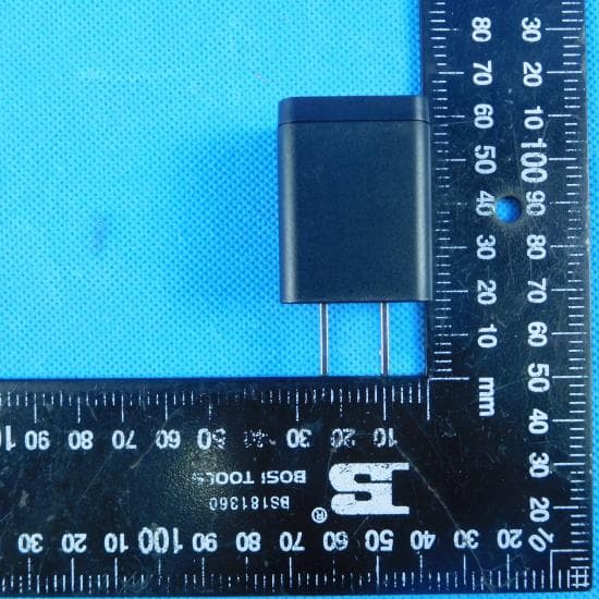
A2HCT9F08
Jun 03, 2021Tablet
Equipment Class
DSS - Part 15 Spread Spectrum Transmitter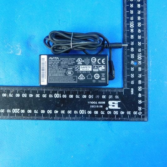
A2HCN6Q15E
Nov 29, 2020Notebook Computer
Equipment Class
DTS - Digital Transmission System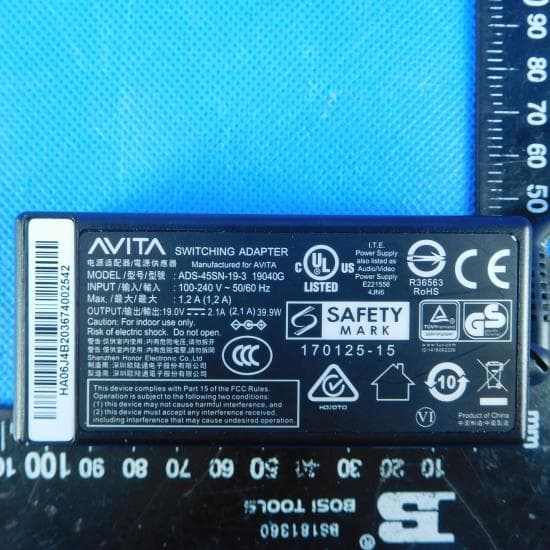
A2HCN6Q15
Oct 27, 2020Notebook Computer
Equipment Class
DTS - Digital Transmission System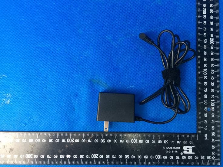
A2HRCT6T48
Oct 11, 2020Tablet
Equipment Class
DSS - Part 15 Spread Spectrum Transmitter