A3LAT46L5DLP Projection TV
Samsung Electronics Co Ltd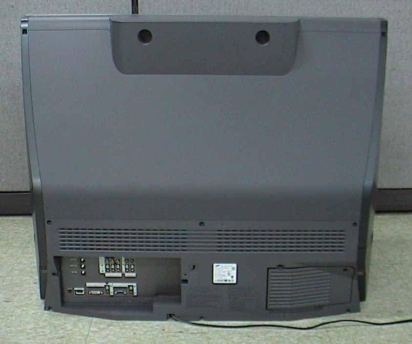
Click to zoom
Application Details
- Equipment Class
- JBP - Part 15 Class B Computing Device Peripheral
- Date of Grant
- Sep 22, 2004
- Application Purpose
- Original Equipment
- Date of Application
- Sep 22, 2004
- Equipment Note
- DLP Projection TV
- Company
- Samsung Electronics Co Ltd
- Country
- United States
Documents & Files
Document Text
Text extracted from the exhibit documents filed with the FCC. Open a document above to read the original.
Users Manual
HL-P4674W DLPTV This device is a Class B digital apparatus. INSTRUCTION MANUAL BP68-00423A-00(cover) 9/2/04 4:51 PM Page 3 Your New Wide TV ............................................................................................6 Replacing the Lamp ................................................................................................6 List of Features .......................................................................................................8 Accessories ...........................................................................................................8 Side Panel Buttons..................................................................................................9 Side Panel Jacks ................................................................................................... 9 Front Panel LED Indicators .....................................................................................10 Rear Panel Jacks ..................................................................................................11 Remote Control ....................................................................................................12 Installing Batteries in the Remote Control.....................................................13 Connections .....................................................................................................16 Connecting VHF and UHF Antennas.......................................................................16 Antennas with 300-ohm Flat Twin Leads .....................................................16 Antennas with 75-ohm Round Leads ...........................................................16 Separate VHF and UHF Antennas ..............................................................17 Connecting Cable TV and VCR..............................................................................18 Cable without a Cable Box .......................................................................18 Cable with a Cable Box that Descrambles All Channels ...............................18 Connecting a Cable Converter Box ............................................................19 Connecting a Cable Converter Box and a VCR ...........................................19 Connecting a Camcorder......................................................................................20 Connecting a DVD Player .....................................................................................21 Connecting to Y,P B,PR...............................................................................21 Connecting to Audio and Video Jacks ........................................................21 Connecting a DTV Set-Top Box ..............................................................................22 Connecting to Y,P B,PR...............................................................................22 Connecting to DVI (Digital Visual Interface) .................................................22 Connecting to R,G,B.................................................................................23 Connecting to HDMI (High Definition Multimedia Interface) ..........................23 Operation........................................................................................................26 Turning the TV On and Off....................................................................................26 Viewing the Menus and On-Screen Displays ...........................................................26 Selecting the Menu Language................................................................................27 Selecting the Antenna Input ...................................................................................27 Memorizing the Channels .....................................................................................28 Adding and Erasing Channels ...............................................................................29 Changing Channels..............................................................................................30 Selecting Your Favorite Channels ...........................................................................31 Scanning the Channels .........................................................................................32 Labeling the Channels ..........................................................................................33 Picture Control .....................................................................................................34 Sound Control .....................................................................................................36 Setting the Clock..................................................................................................38 Setting the Timers .................................................................................................39 Viewing an External Signal Source ........................................................................41 Assigning Names to External Input Mode ...............................................................42 Freezing the Current Picture ..................................................................................43 Remote Control VCR/DVD Buttons..........................................................................43 Table of Contents English - 2 BP68-00423A-00(02~13) 9/2/04 4:08 PM Page 2 Special Features ...............................................................................................46 Customizing Your Remote Control ..........................................................................46 Remote Control Codes ..........................................................................................47 Fine Tuning Channels ...........................................................................................48 LNA (Low Noise Amplifier)....................................................................................49 Selecting the Color Tone .......…
Text truncated - open the document above for the full version.
Users Manual
Regulatory and Safety Compliance Guide The slots and openings in the cabinet and in the back or bottom are provided for necessary ventilation. To ensure reliable operation of this apparatus, and to protect it from overheating, these slots and openings must never be blocked or covered. - Do not cover the slots and openings with a cloth or other materials. - Do not block the slots and openings by placing this apparatus on a bed, sofa, rug or other similar surface. - Do not place this apparatus in a confined space, such as a bookcase, or built-in cabinet, unless proper ventilations is provided. Do not place this apparatus near or over a radiator or heat register, or where it is exposed to direct sunlight. Do not place the sources of heat on this apparatus, such as a candle, ash tray, incense or other similar material. Do not place a water containing vessel on this apparatus, as this can result in a risk of fire or electric shock. Do not expose this apparatus to rain or place it near water(near a bathtub, washbowl, kitchen sink, or laundry tub, in a wet basement, or near a swimming pool etc.). If this appratus accidentally gets wet, unplug it and contact an authorizrd dealer immediately. You can clean this apparatus with damp cloth when necessary, but be sure to unplug the apparatus first. Do not expose this apparatus set to extreme temperature conditions or to extreme humidity conditions. This appratus use batteries. In your community there might be regulations that require you to dispose these batteries properly under environmental considerations. Please contact your local authorities for disposal or recycling information. To cut off the power source, unplug this apparatus from the wall outlet. Do not overload wall outlets, extension cords or convenience receptacles beyond their capacity, since this can result in fire or electric shock. Power-supply cords should be routed so that they are not likely to be walked on or pinched by items placed upon or against them, paying particular attention to cords at plugs, convenience receptacles, and the point where they exit from the appliance. To protect this apparatus from a lightning storm, or when it is left unattended and unused for long periods of time, unplug it from the wall outlet and disconnect the antenna or cable system. This will prevent damage to the set due to lightning and power line surges. Before connecting the AC power cord to the DC adapter outlet, make sure the voltage designation of the DC adapter corresponds the the local electrical supply. Never insert anything metallic into this appratus openings. Doing so many create the danger of electric shock. To avoid electric shock, never touch the inside of this apparatus. Only a qualified technician should open this apparatus's case. Be sure to hold the plug, not the cord, when disconnecting this apparatus from an electric socket. Locate this apparatus near an easily acessible AC outlet. If this appratus does not operate normally - in particular, if there are any unusual sounds or smells coming from it - unplug it immediately and contact an authorized dealer or service center. Unplug this apparatus from the AC outlet before any service. This sysmbol indicated high voltage is present inside. It is dangerous to make any kind of contact with any inside part of this product. This symbol alrerts you that important literature concerning operation and maintenance has been included with this product. Warning! Important Safety Instructions CAUTION R IS KO FE L E C T R ICS H O C K DON O TO P E N CAUTION: TO REDUCE THE RISK OF ELECTRIC SHOCK, DO NOT REMOVE COVER (OR BACK). THERE ARE NO USER SERVICEABLE PARTS INSIDE. REFER ALL SERVUSING TO QUALIFIED PERSONNEL. (Please read the approproate section that corresponds to the marking on your Samsung product before attempting to install the product.) Reg ulatory Com pliance Sta tements YourSamsungproductismarkedtoindicateitscomplianceclass: -FederalCommunicationsCommission(FCC)-USA -IndustryCanadaEquipmentStandardforDigitalEquipment(ICES-003)-Canada -VoluntaryControlCouncilforInterference(VCCI)-Japan -BureauofStandardsMetrologyandInspection(BSMI)-Taiwan -MinistryofInformationandCommunication(MIC)-RepublicofKorea -ItalianPostMinistry(Homologation)-Italy FCCInformation FCCClassANotice Thisdevicecomplieswithpart15oftheFCCRules.Operationissubjecttothefollowingtwo conditions: 1.Thisdevicemaynotcauseharmfulinterference,and 2.Thisdevicemustacceptanyinterferencereceived,includinginterferencethatmaycause undesiredoperation. NOTE:ThisequipmenthasbeentestedandfoundtocomplywiththelimitsforaClassAdigital device,pursuanttoPart15oftheFCCRules.Theselimitsaredesignedtoprovidereasonable protectionagainstharmfulinterferencewhentheequipmentisoperatedinacommercialenvironment. Thisequipmentgenerates,uses,andcanradiateradiofrequencyenergyand,ifnotinstalledand usedinaccordancewiththeinstructionmanual,maycauseharmfulinterferencetoradio communications.Operationofthisequipmentinaresidentialareaislikelytocauseharmful interferenceinwhichcasetheuserwillberequiredtocorrecttheinterferenceathisownexpense. FCCClassBNotice Thisdevicecomplieswithpart15oftheFCCRules.Operationissubjecttothefollowingtwo conditions: 1.Thisdevicemaynotcauseharmfulinterference,and 2.Thisdevicemustacceptanyinterferencereceived,includinginterferencethatmaycause undesiredoperation. NOTE:ThisequipmenthasbeentestedandfoundtocomplywiththelimitsforaClassBdigital device,pursuanttoPart15oftheFCCRules.Theselimitsaredesignedtoprovidereasonable protectionagainstharmfulinterferenceinaresidentialinstallation.Thisequipmentgenerates,uses andcanradiateradiofrequencyenergyand,ifnotinstalledandusedinaccordancewiththe instructions,maycauseharmfulinterferencetoradiocommunications.However,thereisno guarantee that interference will not occur in a particular installation. If this equipment does cause harmful interference to radio or television reception, which can be determined by turning the equipment off and on, the user is encourage…
Text truncated - open the document above for the full version.
Operational Description
Mankind’s early fascination with the viewing of life- like moving images led to the development of a vari- ety of optical gadgets in the 19 th century. One of the earliest was the phenakistoscope, a set of phased drawings mounted on a twirling disk (circa 1832). With the invention of the positive photographic process in 1839 by Daguerre, the drawings were replaced with a succession of phased photographs. These optical toys were based on the understand- ing that a closely spaced series of images could be used to portray a sense of time and motion. This entertainment curiosity was intriguing enough to become a popular and rather sizeable niche business, although the subject or content of the flipping images was of little creative value. Revenues were limited by the fact that only one person could view the images at a time by peering into an eyehole. It was not until the invention of the motion-picture camera, or “Kinetograph,” in 1887 by Thomas Alva Edison, (or his assistant Dickson, as some would argue) that a continuous set of photographic images could be generated. An adjunct to the Kinetograph was a single-viewer apparatus called the “Kinetoscope.” During an exhibition in Paris, a Kinetoscope demonstration inspired the Lumiere brothers, Auguste and Louis, to invent the first com- mercially viable film projector, the “cinematographe.” The first public screening using this new technology was in Paris on December 28, 1895. This event is gen- erally regarded as the birth of the “cinema.” Film projection technology enabled a new business model based on a large (paying) audience who could simultaneously view the same content, thereby allowing higher revenue potential than the early sin- gle-viewer novelties. This fueled the creative passions of the early movie moguls, who founded the movie entertainment business, using photographic film as their capture and display medium. Beyond the increased profit potential, projection technology enabled a large audience to view a motion picture together as a “shared experience,” enhancing the enjoyment in much the same way as when people experience a symphony, play, sports or other group entertainment. JULY–SEPTEMBER19987 DIGITAL LIGHT PROCESSING—INTRODUCTION From cathode rays to digital micromirrors: A history of electronic projection display technology Abstract:In the late 1800s it was called “distant electric vision” or the “electric telescope,” words to describe mankind’s dream to see instantaneously beyond the hori- zon with electric technology. Today we use the word televi- sion. The early window for seeing beyond the horizon was the cathode ray tube or CRT, first demonstrated in crude form in 1897 and developed as a “practical” window in 1929. In the late 1940s following World War II, motion picture studios in concert with the fledgling television industry sought to bring live programming to the movie theater audience. This was the birth of “big-screen” elec- tronic projection display technology. Projection CRTs led the way, but soon, the forerunner of the modern laser dis- play as well as the first spatial light modulator or “light valve” made their commercial debuts. Over the following 50 years, the display industry has searched for the ultimate big-screen technology, not only for the theater, but also for the trade show, classroom, boardroom and living room. An ingenious and sometimes bewildering array of projection technologies has been developed, with the goal of producing brighter, higher fidelity images with displays having lower weight and cost. This article describes those technologies as they evolved, beginning with the early ones based on the CRT and e-beam addressed oil films and continuing to the pre- sent day technologies of improved CRTs, scanned laser beams, the liquid crystal display (LCD), and culminating with the all-digital technology Digital Light Processing™ (DLP™) based on the Digital Micromirror Device™ (DMD™). Larry J. Hornbeck Film-based projection technology has its limita- tions, however, including its inability to provide live content to the audience, the expense of the film prints (including transportation costs) and their inexorable deterioration with repeated screenings. Electronic projection display technology provides an answer to these shortcomings, but the stimulus for its develop- ment had to await the age of commercial television. The grandfather of electronic displays, the CRT or cathode-ray tube, was invented more than 100 years ago. In spite of its age, the CRT is still the dominant display technology today. In the 1940s motion picture studios and the youthful television industry sought to bring live television programming to the theater by using electronic projection technology, but the CRT lacked the necessary brightness. The so-called “light-valve” technologies were developed primarily for sports-driven display venues. In other, less demanding applications, the CRT remained domi- nant because light-valve technologies were too expensive, bulky and heavy. But recently, new light-valve technologies are replacing both the CRT and the older first- and second-generation light valves in high-brightness dis- play venues. And because these new light-valve tech- nologies can be designed into more compact prod- ucts, their availability has opened up new market opportunities where low weight and portability are required. Perhaps soon, the CRT will be replaced in high-end consumer projection display products for the home as well. The projection CRT’s longevity can be attributed to several factors. First, although the projection CRT is considered a “mature” technology, it has been steadily improved over a long period and incremen- tal improvements are even being made today. And second, until recently light-valve technologies were unable to take full advantage of the economies and stability offered by the digital electronics revolution. This digital age has brought us such advanced ser- vices and products as the Intern…
Text truncated - open the document above for the full version.
Test Report
1 of 20 Samsung EMC Testing and Certification Laboratory Project No: LBE041737 This report shall not be reproduced except in full, without the written approval of SEC EMC Testing laboratory. EMC Test Report According to FCC Part 15 Subpart B Project No. LBE041737 Equipment under Test Applicant Samsung Electronics Co. Ltd; 416 Maetan-3 Dong, Paldal-Ku, Suwon City, Kyungki-Do, Korea, 442-742 FCC ID A3LAT46L5 Product Name DLP PROJECTION TV Model Name AT46L5 Manufacturer Samsung Electronics Co. Ltd Date of Test August 26 ~ September 20, 2004 Issued Date September 20, 2004 Name/Position Signature Tested by Jang Tae Young Test Engineer Reviewed by No Cheon, Park Manager of EMC Lab. Authorized by Kyu Baek, Chung Chief of EMC Lab. 1. This test reports does not constitute an endorsement by NIST/NVLAP or U.S Government. 2. This test report is to certify that the tested device properly complies with the requirements of FCC Rules and Regulations Part 15 Subpart B Unintentional Radiators. All tests necessary to show compliance to the requirements were and these results met the specifications requirement. This laboratory is registered by the NIST/NVLAP, U.S.A. The test reported herein have been performed in accordance with its terms of registration. 2 of 20 Samsung EMC Testing and Certification Laboratory Project No: LBE041737 This report shall not be reproduced except in full, without the written approval of SEC EMC Testing laboratory. Table of Contents 1. General Information 1.1 Basic Information related Product 1.2 Detail Information related Product 1.3 Test Configuration 1.4 EUT Operating Conditions 1.5 Applied Standard 1.6 Test Facility 2. Summary of Test Results 3. Description of individual tests 3.1 Conducted Emission 3.2 Radiated Emission 4. Appendix 4.1 Test Photography 4.2 EUT Photography 3 of 20 Samsung EMC Testing and Certification Laboratory Project No: LBE041737 This report shall not be reproduced except in full, without the written approval of SEC EMC Testing laboratory. 1. General Information 1.1 Basic Information related Product Applicant Samsung Electronics Co. Ltd; Model name AT46L5 Applicant Address Samsung Electronics Co. Ltd; 416 Maetan3- Dong, Yeoung tong-Ku, Suwon City, Gyeonggi-Do, Korea, 443-742 Contact Person Kind of product DLP PROJECTION TV Valiant list None Manufacturer Samsung Electronics Co. Ltd; 1.2 Detail Information related Product Specification Resolution 1280 * 720 Horizontal Frequency 60kHz Vertical Frequency 75Hz 1.3 Operating Mode and Condition The system was configured for testing in typical fashion use. The mode of operation utilized for testing was selected to best simulate typical EUT use. - PC Video Input - PC DVI Input The EUT Exercise program used during radiated and conducted testing was designed to exercise the various system components in a manner similar to typical use. 1.4 Equipment Modifications No equipment modifications were required. 4 of 20 Samsung EMC Testing and Certification Laboratory Project No: LBE041737 This report shall not be reproduced except in full, without the written approval of SEC EMC Testing laboratory. 1.5 Test Procedure 1.5.1 Disturbance Voltage at Mains EUT was placed on a platform nominal size, 1m by 1.5m, raised 80cm above the conducti ng ground plane. The rear of tabletop was located 40cm to the vertical conducting groud plane. The rear of EUT, including peripherals was aligned and flush with rear of tabletop. All other surfaces of tabletop was at least 80cm from any other grounded conducing surface. I/O cables and AC cables that were connected to the peripherals were bundled in center. They were folded back and forth forming a bindle 30cm to 40cm long and were handed at a 40cm height to the ground plane. Each EUT current-carrying power lead, except the ground(safety)lead, were individually connected through a LISN to the input power source. All unused 50 ohm connectors of the LISN were resistively terminated in 50 ohm when not connected to the measuring equipment. 1.5.2 Radiated disturbance EUT was placed on a platform of nominal size, 1m by 1.5m, raised 80cm above the conducting ground plane. The rear of EUT, including peripherals was aligned and flush with rear of tabletop. I/O cables that were connected to the peripherals were bundle in center. They were folded back and forth forming a bundle 30cm to 40cm long and were hanged 40cm height to the ground plane. Test was made with the antenna positioned in both the horizontal and vertical planes of polarization. The measurement antenna was varied in height above the conducting ground plane and the run table azimuth was varied to obtain the maximum signal strength The system configuration, clock speed, mode of operation or video resolution, turntable azimuth with respect to the antenna were noted for each frequency found. The spectrum was scanned from 30 to 1000 MHz using biconiLog antenna. 5 of 20 Samsung EMC Testing and Certification Laboratory Project No: LBE041737 This report shall not be reproduced except in full, without the written approval of SEC EMC Testing laboratory. 1.6 Test Configuration Used EUT and Peripherals Seq Device Model Name Serial # Maker Note A DLP Projection TV AT46L5 - SAMSUNG B PC M6050 812092FRC2822 SAMSUNG DoC C Printer ML-1750 - SAMSUNG A3LML1750 D PS/2 Keyboard SK-8110 MY-04N729-71619- 43P-6033 DELL DoC E PS/2 Mouse MO71KC 402008157 DELL DoC Used Cable Description Connect Cable Length [m] Shielded [Y/N] Remark 1 Parallel (Printer) 1.7 Yes 2 Monitor 1.5 Yes 3 DVI 1.5 Yes 4 USB 1.5 Yes 5 PS/2 1.5 Yes 6 Component Video Out 1.5 No 7 AV front IN 1.5 No 8 Audio Out 1.5 No 9 S -Video Out 1.5 Yes 10 Audio Out 1.5 No 6 of 20 Samsung EMC Testing and Certification Laboratory Project No: LBE041737 This report shall not be reproduced except in full, without the written approval of SEC EMC Testing laboratory. Block Diagram 1.7 Applied Standards List Applied Standards Test Procedure FCC Part15 ANSI C63.4 : 2000 Performance Criteria A. normal performance with…
Text truncated - open the document above for the full version.
Test Setup Photos
17 of 20 Samsung EMC Testing and Certification Laboratory Project No: LBE041737 This report shall not be reproduced except in full, without the written approval of SEC EMC Testing laboratory. 4. Appendix 4.1 Test Photography Pic. 1 Conducted Emission (Front) Pic. 2 Conducted Emission (Rear) 18 of 20 Samsung EMC Testing and Certification Laboratory Project No: LBE041737 This report shall not be reproduced except in full, without the written approval of SEC EMC Testing laboratory. Pic. 3 Radiated Emission (Front) Pic. 4 Radiated Emission (Rear)
Contact Information
Applicant
Jenni Chun(General Manager)
Technical Contact
PCTEST Engineering Lab., Inc.Randy Ortanez
[email protected]410-290-6652
6660-B Dobbin Road · Columbia, Maryland · United States
Test Firm
SAMSUNG ELECTRONICS CO., LTD.No Cheon Park
Technical Specifications
| # | Rule Parts | Frequency Range | Power Output |
|---|---|---|---|
| 1 | 15B | - | - |
Other Applications from Samsung Electronics Co Ltd
A3LSMS741B
Aug 05, 2026Portable Handset
Equipment Class
6VL - 15E 6 GHZ Very Low Power DeviceA3LSMX940
Jul 31, 2026BT,BLE Tablet DTS,UNII a,b,g,n,ac,ax,be and digitizer
Equipment Class
DTS - Digital Transmission SystemA3LSMS741U
Jul 30, 2026Portable Handset
Equipment Class
6CD - 15E 6 GHz Low Power Dual ClientA3LSMX840
Jul 27, 2026BT,BLE Tablet DTS,UNII a,b,g,n,ac,ax and Digitizer
Equipment Class
DSS - Part 15 Spread Spectrum TransmitterA3LSMX848U
Jul 27, 2026WCDMA, LTE, 5G NR Tablet BT,BLE, DTS,UNII a b g n ac ax and Digitizer
Equipment Class
JBP - Part 15 Class B Computing Device Peripheral