A4R-NX747517 inch Tablet
Google LLC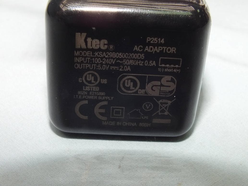
Click to zoom
Application Details
- Equipment Class
- DTS - Digital Transmission System
- Date of Grant
- Sep 03, 2014
- Application Purpose
- Original Equipment
- Date of Application
- Sep 03, 2014
- Equipment Note
- 7 inch Tablet
- Frequency Range
- 2412.00000000 - 2462.00000000
- Company
- Google LLC
- Country
- United States
Documents & Files
Document Text
Text extracted from the exhibit documents filed with the FCC. Open a document above to read the original.
Users Manual
8/12/2014Project Tango Tablet User Guide - Project Tango — Google Developers https://devsite.googleplex.com/project-tango/hardware/tablet1/4 XProject Tango Search [email protected] Sign out Project Tango Tablet User Guide Get started Insert & activate a SIM card Charge the battery Set up your tablet Stay up to date Try some apps Hardware reference Troubleshooting and support Close applications for better performance Calibration files Support Get started Insert & activate a SIM card To use your tablet with mobile network data, you must first insert & activate a SIM card. if no card is installed, the message “No SIM card” appears on the tablet’s lock screen. Warning: The SIM card ejection tool and the SIM card tray included with the Project Tango tablet are very small objects that represent a choking hazard. Please keep them out of reach of small children. To insert a new SIM card: 1. Turn your tablet off and place it on a flat surface with the screen facing up and the camera at the top. 2. Tilt the right side slightly and locate the SIM card tray near the middle and the small hole in the tray door. 3. Insert the SIM ejection tool that comes with the tablet (or a paperclip) into the hole on the tray, and push firmly but gently until the tray pops out. 4. Remove the tray and place the micro SIM card inside it, with the angled corner fitting snugly into the angled corner of the tray. 5. Carefully reposition the tray in the slot and push it gently back into the tablet. To activate a SIM card: 1. After completing the setup instructions, open the settings app and turn off Wi-Fi. Once Wi-Fi is off, you’ll see a notification at the top of your screen. 2. Swipe down the notification shade and touch the notification. 3. Follow the activation instructions provided by your carrier. Products Project Tango 8/12/2014Project Tango Tablet User Guide - Project Tango — Google Developers https://devsite.googleplex.com/project-tango/hardware/tablet2/4 Important: Some carriers may take a minute or more to activate your SIM card. If you find it’s taking a long time to activate, you may want to try restarting your tablet. some mobile service providers may require you to enter and then exit airplane mode, or to use an SMS app from the Google Play store to manage your data. Contact your own mobile service provider for additional details. Charge the battery Your battery will not be fully charged when you first unpack your Project Tango tablet. It’s a good idea to fully charge the battery as soon as you get a chance. Connect the small end of the Micro USB cable to the Micro USB port on the upper left edge of the tablet, when viewed from the front. Then connect the other end to the charging unit, and the charging unit to a power outlet. The USB charging unit is certified for worldwide use and comes with a number of global plug adapters. Use only the USB charging unit and Micro USB cable that come with your Project Tango tablet. Using a different charging unit or cable may damage your tablet. The input voltage range between the wall outlet and this charging unit is AC 100V–240V, and the charging unit’s output voltage is DC 5V, 2A. The best power source is the charging unit that comes with your tablet. Other sources, such as a laptop, may not work as well. The tablet charges faster when you’re not using it. The mini-dock accepts a power adapter for faster charging (not provided). The power adapter output must be 12V, 2A, and the connector must be a barrel plug with 5.5mm outer diameter, 2.1mm inner diameter. Set up your tablet To turn on your Project Tango tablet, press the Power button on the top right edge for a few seconds, then release it. When you first turn on your tablet, you’ll see a Welcome screen. Choose the language you want and touch Start or the Start icon. Important: You must have a Wi-Fi connection to complete the setup process. When prompted, you can sign in with your Google Account or cre-ate one at that time. You can also choose to skip this step and create one later. An email address that you use for any of the following counts as a Google Account: Gmail YouTube Google Apps AdWords Any other Google product When you sign in with a Google Account, all the email, contacts, Calendar events, and other data associated with that account are automatically synced with your tablet. If you have multiple Google Accounts, you can add others later from Settings > Accounts > Add account. Stay up to date 8/12/2014Project Tango Tablet User Guide - Project Tango — Google Developers https://devsite.googleplex.com/project-tango/hardware/tablet3/4 Project Tango tablets receive Over-The-Air (OTA) updates on a regular basis to provide firmware, system, and system application updates. When an OTA update is available, a notification window appears. If you choose to install the OTA update immediately, the process may take up to 10 minutes. The battery must be at least 25% charged to begin the update. We recommend charging the device while the update runs to avoid any interruptions. If you choose "Install later", you can set a time for the install to occur. A reminder to install the update will remain in the notification drawer, accessible by swiping down on the system bar at the top of the screen. You can also go to Settings > About tablet > System updates to check for an update or install an available update. To check the software build version that your Tango device is running, go to Settings > About tablet > Build number. Build numbers are based on their release date in YYMMDD format. For example, Build 140514 corresponds to May 14, 2014. Try some apps Visit the demos page for a list of demos made by the Project Tango team showcasing some of the functionality of Project Tango devices. We hope they serve as inspiration to you to create brand new experiences for Project Tango. Hardware reference Visit the hardware reference page for technical specifications and other information about the device. Troubleshooting and supp…
Text truncated - open the document above for the full version.
Cover Letter(s)
SCS-F18: Project and Product Certification Representative Authorization Letter Page 1 of 2 Rev 3.0 775 Montague Expressway Milpitas, CA 95035 Tel: 408-526-1188 Fax: 408-526-1088 Email: [email protected] Project and Product Certification Representative Authorization Letter Reason for Amendment (current / obsolete) Revision History Approved Date From To Initial Release (obsolete) 1.0 1.0 Nov-14-2006 Revised wording (obsolete) 1.0 2.0 Sept–25-2007 Updated company template (current) 2.0 3.0 Jan-31-2012 SCS-F18: Project and Product Certification Representative Authorization Letter Page 2 of 2 Rev 3.0 August 20, 2014 To: SIEMIC, INC. 775 Montague Expressway, Milpitas, CA 95035 USA Dear Sir/Madam, Re: Project and Product Certification Representative Authorization Letter We, Google Inc hereby authorize SIEMIC, INC. to act as a Certification Body for certifying for the following project(s): 7" Tablet / A4R-NX74751 We affirm that between SIEMIC and Google Inc, any difference in understanding, including test plan, measurement methods, applicable standards and relevant procedures and processes have been resolved prior to commencement of testing activities. Sincerely, _____________________ Daniel Lee / Vice President Bureau Veritas Consumer Products Services (H.K.) Ltd., Taoyuan Branch Tel: +886 3 318 3232 #1857
Cover Letter(s)
1600 Amphitheatre Parkway, Mountain View, California, United States 94043 Date: August 7, 2014 Power of Attorney To whom it may concern, Please be notified that I, Warwick Wong, have designated Daniel Lee of Bureau Veritas Consumer Products Services (H.K.) Ltd., Taoyuan Branch (BV CPS Taoyuan Branch) of Taiwan and Onion Yang of Compal Electronics Inc as the persons being responsible for this project and to sign the form 731 and other documentation. Any and all acts, including communications with the FCC, carried out by Mr. Lee and Onion Yang of Compal Electronics Inc on matters relating to FCC approval processes shall have the same legal authority as acts on our own behalf. As defined in 47 CFR Ch. 1.2002 (b), we further certify that neither the applicant nor any party to this application is subject to a denial to Federal benefits, including FCC benefits, pursuant to section 5301 of the Anti-Drug Abuse Act of 1998, 21 U.S.C. 835(a). This authorization is limited to the following product: FCC ID: A4R-NX74751 Please send any acknowledgement and response to Mr. Lee directly. Otherwise, should you have any questions or comments regarding this matter, please do not hesitate to contact the undersigned. Sincerely yours, Warwick Wong / Regulatory Compliance Specialist Google Inc. Fax: 1-650-253-8006 Tel: 1-408-425-6290 E-mail: [email protected]
External Photos
Report No.: 140620C11 1 of 23 CONSTRUCTION PHOTOS OF EUT Report No.: 140620C11 2 of 23 Report No.: 140620C11 3 of 23
Internal Photos
Report No.: 140620C11 1 of 20 CONSTRUCTION PHOTOS OF EUT Report No.: 140620C11 2 of 20 Report No.: 140620C11 3 of 20 Report No.: 140620C11 4 of 20 Report No.: 140620C11 5 of 20 Report No.: 140620C11 6 of 20 Report No.: 140620C11 7 of 20 Report No.: 140620C11 8 of 20 Report No.: 140620C11 9 of 20 Report No.: 140620C11 10 of 20 Report No.: 140620C11 11 of 20 Report No.: 140620C11 12 of 20 Report No.: 140620C11 13 of 20 Report No.: 140620C11 14 of 20 Report No.: 140620C11 15 of 20 Report No.: 140620C11 16 of 20 Report No.: 140620C11 17 of 20 Report No.: 140620C11 18 of 20 Report No.: 140620C11 19 of 20 Report No.: 140620C11 20 of 20
RF Exposure Info
FCC SAR Test Report Report Format Version 5.0.0 Page No. : 1 of 52 Report No. : SA140620C11 Issued Date : Aug. 27, 2014 FCC SAR Test Report Report No. : SA140620C11 Applicant : Google Inc. Address : 1600 Amphitheatre Parkway Mountain View California, United States Product : 7” Tablet FCC ID : A4R-NX74751 Brand : Google Model No. : NX-74751 Standards : FCC 47 CFR Part 2 (2.1093) / IEEE C95.1:1992 / IEEE 1528:2003 IEEE 1528a-2005 / KDB 865664 D01 v01r03 / KDB 248227 D01 v01r02 KDB 447498 D01 v05r02 / KDB 616217 D04 v01r01 / KDB 941225 D01 v02 KDB 941225 D02 v02r02 / KDB 941225 D03 v01 / KDB 941225 D05 v02r03 Sample Received Date : Jun. 20, 2014 Date of Testing : Jul. 18, 2014 ~ Aug. 27, 2014 CERTIFICATION: The above equipment have been tested by Bureau Veritas Consumer Products Services (H.K.) Ltd., Taoyuan Branch – Lin Kou Laboratories, and found compliance with the requirement of the above standards. The test record, data evaluation & Equipment Under Test (EUT) configurations represented herein are true and accurate accounts of the measurements of the sample’s SAR characteristics under the conditions specified in this report. It should not be reproduced except in full, without the written approval of our laboratory. The client should not use it to claim product certification, approval, or endorsement by TAF or any government agencies. Prepared By : Evonne Liu / Specialist Approved By : Roy Wu / Manager This report is for your exclusive use. Any copying or replication of this report to or for any other person or entity, or use of our name or trademark, is permitted only with our prior written permission. This report sets forth our findings solely with respect to the test samples identified herein. The results set forth in this report are not indicative or representative of the quality or characteristics of the lot from which a test sample was taken or any similar or identical product unless specifically and expressly noted. Our report includes all of the tests requested by you and the results thereof based upon the information that you provided to us. You have 60 days from date of issuance of this report to notify us of any material error or omission caused by our negligence, provided, however, that such notice shall be in writing and shall specifically address the issue you wish to raise. A failure to raise such issue within the prescribed time shall constitute your unqualified acceptance of the completeness of this report, the tests conducted and the correctness of the report contents. Unless specific mention, the uncertainty of measurement has been explicitly taken into account to declare the compliance or non-compliance to the specification. FCC SAR Test Report Report Format Version 5.0.0 Page No. : 2 of 52 Report No. : SA140620C11 Issued Date : Aug. 27, 2014 Table of Contents Release Control Record ............................................................................................................................................................... 3 1. Summary of Maximum SAR Value ....................................................................................................................................... 4 2. Description of Equipment Under Test ................................................................................................................................. 5 3. SAR Measurement System ................................................................................................................................................... 6 3.1 Definition of Specific Absorption Rate (SAR) ............................................................................................................... 6 3.2 SPEAG DASY System ................................................................................................................................................. 6 3.2.1 Robot.................................................................................................................................................................. 7 3.2.2 Probes ................................................................................................................................................................ 8 3.2.3 Data Acquisition Electronics (DAE) .................................................................................................................... 8 3.2.4 Phantoms ........................................................................................................................................................... 9 3.2.5 Device Holder ................................................................................................................................................... 10 3.2.6 System Validation Dipoles ................................................................................................................................ 10 3.2.7 Tissue Simulating Liquids ................................................................................................................................. 11 3.3 SAR System Verification ............................................................................................................................................ 14 3.4 SAR Measurement Procedure ................................................................................................................................... 15 3.4.1 Area & Zoom Scan Procedure ......................................................................................................................... 15 3.4.2 Volume Scan Procedure................................................................................................................................... 15 3.4.3 Power Drift Monitoring ...................................................................................................................................... 16 3.4.4 Spatial Peak SAR Evaluation ...........................................................................................…
Text truncated - open the document above for the full version.
RF Exposure Info
FCC SAR Test Report Report Format Version 5.0.0 Issued Date : Aug. 27, 2014 Report No. : SA140620C11 Appendix A. SAR Plots of System Verification The plots for system verification with largest deviation for each SAR system combination are shown as follows. Test Laboratory: Bureau Veritas ADT SAR/HAC Testing Lab Date: 2014/07/23 System Check_B750_140723 DUT: Dipole 750 MHz; Type: D750V3; SN: 1013 Communication System: CW; Frequency: 750 MHz;Duty Cycle: 1:1 Medium: B07T08N2_0723 Medium parameters used: f = 750 MHz; σ = 0.966 S/m; ε r = 55.257; ρ = 1000 kg/m 3 DASY5 Configuration: - Probe: EX3DV4 - SN3578; ConvF(8.59, 8.59, 8.59); Calibrated: 2014/06/24; - Sensor-Surface: 2mm (Mechanical Surface Detection) - Electronics: DAE3 Sn579; Calibrated: 2014/04/23 - Phantom: ELI v5.0_Right; Type: QD OVA 002 AA; Serial: SN:1245 - Measurement SW: DASY52, Version 52.8 (8); SEMCAD X Version 14.6.10 (7331) Pin=250mW/Area Scan (61x81x1): Interpolated grid: dx=1.500 mm, dy=1.500 mm Maximum value of SAR (interpolated) = 2.88 W/kg Pin=250mW/Zoom Scan (5x5x7)/Cube 0: Measurement grid: dx=8mm, dy=8mm, dz=5mm Reference Value = 55.57 V/m; Power Drift = -0.02 dB Peak SAR (extrapolated) = 3.40 W/kg SAR(1 g) = 2.27 W/kg; SAR(10 g) = 1.51 W/kg Maximum value of SAR (measured) = 2.88 W/kg Test Laboratory: Bureau Veritas ADT SAR/HAC Testing Lab Date: 2014/07/19 System Check_B835_140719 DUT: Dipole 835 MHz; Type: D835V2; SN: 4d121 Communication System: CW; Frequency: 835 MHz;Duty Cycle: 1:1 Medium: B08T09N1_0719 Medium parameters used: f = 835 MHz; σ = 0.988 S/m; ε r = 54.796; ρ = 1000 kg/m 3 Ambient Temperature:22.6 °C; Liquid Temperature:21.3 °C DASY5 Configuration: - Probe: EX3DV4 - SN3650; ConvF(9.18, 9.18, 9.18); Calibrated: 2014/4/24; - Sensor-Surface: 2mm (Mechanical Surface Detection) - Electronics: DAE3 Sn360; Calibrated: 2014/02/17 - Phantom: SAM Phantom_Back; Type: QD000P40CD; Serial: TP 1654 - Measurement SW: DASY52, Version 52.8 (8); SEMCAD X Version 14.6.10 (7331) Pin=250mW/Area Scan (61x61x1): Interpolated grid: dx=1.500 mm, dy=1.500 mm Maximum value of SAR (interpolated) = 2.93 W/kg Pin=250mW/Zoom Scan (5x5x7)/Cube 0: Measurement grid: dx=8mm, dy=8mm, dz=5mm Reference Value = 51.99 V/m; Power Drift = 0.01 dB Peak SAR (extrapolated) = 3.47 W/kg SAR(1 g) = 2.3 W/kg; SAR(10 g) = 1.5 W/kg Maximum value of SAR (measured) = 2.91 W/kg Test Laboratory: Bureau Veritas ADT SAR/HAC Testing Lab Date: 2014/07/23 System Check_B835_140723 DUT: Dipole 835 MHz; Type: D835V2; SN: 4d121 Communication System: CW; Frequency: 835 MHz;Duty Cycle: 1:1 Medium: B08T09N2_0723 Medium parameters used: f = 835 MHz; σ = 0.974 S/m; ε r = 55.307; ρ = 1000 kg/m 3 DASY5 Configuration: - Probe: EX3DV4 - SN3578; ConvF(8.48, 8.48, 8.48); Calibrated: 2014/06/24; - Sensor-Surface: 2mm (Mechanical Surface Detection) - Electronics: DAE3 Sn579; Calibrated: 2014/04/23 - Phantom: ELI v5.0_Right; Type: QD OVA 002 AA; Serial: SN:1245 - Measurement SW: DASY52, Version 52.8 (8); SEMCAD X Version 14.6.10 (7331) Pin=250mW/Area Scan (61x81x1): Interpolated grid: dx=1.500 mm, dy=1.500 mm Maximum value of SAR (interpolated) = 3.13 W/kg Pin=250mW/Zoom Scan (5x5x7)/Cube 0: Measurement grid: dx=8mm, dy=8mm, dz=5mm Reference Value = 57.60 V/m; Power Drift = 0.07 dB Peak SAR (extrapolated) = 3.65 W/kg SAR(1 g) = 2.52 W/kg; SAR(10 g) = 1.67 W/kg Maximum value of SAR (measured) = 3.16 W/kg Test Laboratory: Bureau Veritas ADT SAR/HAC Testing Lab Date: 2014/07/18 System Check_B1750_140718 DUT: Dipole 1750 MHz; Type: D1750V2; SN: 1055 Communication System: CW; Frequency: 1750 MHz;Duty Cycle: 1:1 Medium: B17T18N1_0718 Medium parameters used: f = 1750 MHz; σ = 1.471 S/m; ε r = 53.784; ρ = 1000 kg/m 3 Ambient Temperature:21.6 °C; Liquid Temperature:21.4 °C DASY5 Configuration: - Probe: EX3DV4 - SN3820; ConvF(7.48, 7.48, 7.48); Calibrated: 2014/05/15; - Sensor-Surface: 2mm (Mechanical Surface Detection) - Electronics: DAE4 Sn1431; Calibrated: 2014/03/24 - Phantom: SAM Phantom_Left; Type: SAM V4.0; Serial: TP 1653 - Measurement SW: DASY52, Version 52.8 (8); SEMCAD X Version 14.6.10 (7331) Pin=250mW/Area Scan (61x61x1): Interpolated grid: dx=1.500 mm, dy=1.500 mm Maximum value of SAR (interpolated) = 12.1 W/kg Pin=250mW/Zoom Scan (5x5x7)/Cube 0: Measurement grid: dx=8mm, dy=8mm, dz=5mm Reference Value = 92.91 V/m; Power Drift = -0.09 dB Peak SAR (extrapolated) = 14.8 W/kg SAR(1 g) = 8.64 W/kg; SAR(10 g) = 4.68 W/kg Maximum value of SAR (measured) = 12.1 W/kg Test Laboratory: Bureau Veritas ADT SAR/HAC Testing Lab Date: 2014/08/05 System Check_B1750_140805 DUT: Dipole 1750 MHz; Type: D1750V2; SN: 1055 Communication System: CW; Frequency: 1750 MHz;Duty Cycle: 1:1 Medium: B17T18N1_0805 Medium parameters used: f = 1750 MHz; σ = 1.498 S/m; ε r = 52.238; ρ = 1000 kg/m 3 DASY5 Configuration: - Probe: EX3DV4 - SN3578; ConvF(7.32, 7.32, 7.32); Calibrated: 2014/06/24; - Sensor-Surface: 2mm (Mechanical Surface Detection) - Electronics: DAE3 Sn579; Calibrated: 2014/04/23 - Phantom: SAM Phantom_Front; Type: SAM V4.0; Serial: TP 1202 - Measurement SW: DASY52, Version 52.8 (8); SEMCAD X Version 14.6.10 (7331) Pin=250mW/Area Scan (61x61x1): Interpolated grid: dx=1.500 mm, dy=1.500 mm Maximum value of SAR (interpolated) = 14.0 W/kg Pin=250mW/Zoom Scan (5x5x7)/Cube 0: Measurement grid: dx=8mm, dy=8mm, dz=5mm Reference Value = 95.04 V/m; Power Drift = 0.11 dB Peak SAR (extrapolated) = 16.5 W/kg SAR(1 g) = 9.45 W/kg; SAR(10 g) = 5.09 W/kg Maximum value of SAR (measured) = 13.0 W/kg Test Laboratory: Bureau Veritas ADT SAR/HAC Testing Lab Date: 2014/08/05 System Check_B1900_140805 DUT: Dipole 1900 MHz; Type: D1900V2; SN: 5d036 Communication System: CW; Frequency: 1900 MHz;Duty Cycle: 1:1 Medium: B18T19N1_0805 Medium parameters used: f = 1900 MHz; σ = 1.551 S/m; ε r = 52.684; ρ = 1000 kg/m 3 DASY5 Configuration: - Probe: EX3DV4 - SN3578; ConvF(6.86, 6.86, 6.86); Calibrated: 2014/06/24; - Sensor-Surface: 2mm (Mechanical Surface Detection) - Electronics: DAE3 Sn579; Calibrated: 2014/04/23 - Phanto…
Text truncated - open the document above for the full version.
RF Exposure Info
FCC SAR Test Report Report Format Version 5.0.0 Issued Date : Aug. 18, 2014 Report No. : SA140620C11 Appendix B. SAR Plots of SAR Measurement The SAR plots for highest measured SAR in each exposure configuration, wireless mode and frequency band combination, and measured SAR > 1.5 W/kg are shown as follows. Test Laboratory: Bureau Veritas ADT SAR/HAC Testing Lab Date: 2014/07/19 P01 GSM850_GPRS12_Top Side_0mm_Ch128 DUT: 140620C11 Communication System: GPRS12; Frequency: 824.2 MHz;Duty Cycle: 1:2 Medium: B08T09N1_0719 Medium parameters used: f = 824.2 MHz; σ = 0.973 S/m; ε r = 54.913; ρ = 1000 kg/m 3 Ambient Temperature:22.6 °C; Liquid Temperature:21.3 °C DASY5 Configuration: - Probe: EX3DV4 - SN3650; ConvF(9.18, 9.18, 9.18); Calibrated: 2014/4/24; - Sensor-Surface: 2mm (Mechanical Surface Detection) - Electronics: DAE3 Sn360; Calibrated: 2014/02/17 - Phantom: SAM Phantom_Back; Type: QD000P40CD; Serial: TP 1654 - Measurement SW: DASY52, Version 52.8 (8); SEMCAD X Version 14.6.10 (7331) - Area Scan (31x151x1): Interpolated grid: dx=1.500 mm, dy=1.500 mm Maximum value of SAR (interpolated) = 1.03 W/kg - Zoom Scan (5x5x7)/Cube 0: Measurement grid: dx=8mm, dy=8mm, dz=5mm Reference Value = 26.47 V/m; Power Drift = 0.03 dB Peak SAR (extrapolated) = 2.19 W/kg SAR(1 g) = 1 W/kg; SAR(10 g) = 0.488 W/kg Maximum value of SAR (measured) = 1.39 W/kg Test Laboratory: Bureau Veritas ADT SAR/HAC Testing Lab Date: 2014/08/05 P02 GSM1900_GPRS12_Top Side_0mm_Ch512_w/ Pw Reduction DUT: 140620C11 Communication System: GPRS12; Frequency: 1850.2 MHz;Duty Cycle: 1:2 Medium: B18T19N1_0805 Medium parameters used: f = 1850.2 MHz; σ = 1.496 S/m; ε r = 52.862; ρ = 1000 kg/m 3 DASY5 Configuration: - Probe: EX3DV4 - SN3578; ConvF(6.86, 6.86, 6.86); Calibrated: 2014/06/24; - Sensor-Surface: 2mm (Mechanical Surface Detection) - Electronics: DAE3 Sn579; Calibrated: 2014/04/23 - Phantom: SAM Phantom_Front; Type: SAM V4.0; Serial: TP 1202 - Measurement SW: DASY52, Version 52.8 (8); SEMCAD X Version 14.6.10 (7331) - Area Scan (31x141x1): Interpolated grid: dx=1.500 mm, dy=1.500 mm Maximum value of SAR (interpolated) = 0.859 W/kg - Zoom Scan (5x5x7)/Cube 0: Measurement grid: dx=8mm, dy=8mm, dz=5mm Reference Value = 10.08 V/m; Power Drift = -0.02 dB Peak SAR (extrapolated) = 1.46 W/kg SAR(1 g) = 0.669 W/kg; SAR(10 g) = 0.284 W/kg Maximum value of SAR (measured) = 1.10 W/kg Test Laboratory: Bureau Veritas ADT SAR/HAC Testing Lab Date: 2014/08/05 P03 WCDMA II_RMC12.2K_Top Side_9mm_Ch9262_w/o Pw Reduction DUT: 140620C11 Communication System: WCDMA; Frequency: 1852.4 MHz;Duty Cycle: 1:1 Medium: B18T19N1_0805 Medium parameters used: f = 1852.4 MHz; σ = 1.498 S/m; ε r = 52.855; ρ = 1000 kg/m 3 DASY5 Configuration: - Probe: EX3DV4 - SN3578; ConvF(6.86, 6.86, 6.86); Calibrated: 2014/06/24; - Sensor-Surface: 2mm (Mechanical Surface Detection) - Electronics: DAE3 Sn579; Calibrated: 2014/04/23 - Phantom: SAM Phantom_Front; Type: SAM V4.0; Serial: TP 1202 - Measurement SW: DASY52, Version 52.8 (8); SEMCAD X Version 14.6.10 (7331) - Area Scan (31x141x1): Interpolated grid: dx=1.500 mm, dy=1.500 mm Maximum value of SAR (interpolated) = 1.54 W/kg - Zoom Scan (5x5x7)/Cube 0: Measurement grid: dx=8mm, dy=8mm, dz=5mm Reference Value = 11.15 V/m; Power Drift = -0.08 dB Peak SAR (extrapolated) = 1.82 W/kg SAR(1 g) = 0.965 W/kg; SAR(10 g) = 0.497 W/kg Maximum value of SAR (measured) = 1.36 W/kg Test Laboratory: Bureau Veritas ADT SAR/HAC Testing Lab Date: 2014/07/18 P04 WCDMA IV_RMC12.2K_Top Side_9mm_Ch1513_w/o Pw Reduction DUT: 140620C11 Communication System: WCDMA; Frequency: 1752.6 MHz;Duty Cycle: 1:1 Medium: B17T18N1_0718 Medium parameters used: f = 1753 MHz; σ = 1.474 S/m; ε r = 53.777; ρ = 1000 kg/m 3 Ambient Temperature:21.6 °C; Liquid Temperature:21.4 °C DASY5 Configuration: - Probe: EX3DV4 - SN3820; ConvF(7.48, 7.48, 7.48); Calibrated: 2014/05/15; - Sensor-Surface: 2mm (Mechanical Surface Detection) - Electronics: DAE4 Sn1431; Calibrated: 2014/03/24 - Phantom: SAM Phantom_Left; Type: SAM V4.0; Serial: TP 1653 - Measurement SW: DASY52, Version 52.8 (8); SEMCAD X Version 14.6.10 (7331) - Area Scan (31x151x1): Interpolated grid: dx=1.500 mm, dy=1.500 mm Maximum value of SAR (interpolated) = 1.69 W/kg - Zoom Scan (5x5x7)/Cube 0: Measurement grid: dx=8mm, dy=8mm, dz=5mm Reference Value = 14.33 V/m; Power Drift = 0.08 dB Peak SAR (extrapolated) = 2.47 W/kg SAR(1 g) = 1.41 W/kg; SAR(10 g) = 0.721 W/kg Maximum value of SAR (measured) = 1.82 W/kg Test Laboratory: Bureau Veritas ADT SAR/HAC Testing Lab Date: 2014/07/23 P05 WCDMA V_RMC12.2K_Top Side_0mm_Ch4182 DUT: 140620C11 Communication System: WCDMA; Frequency: 836.4 MHz;Duty Cycle: 1:1 Medium: B08T09N2_0723 Medium parameters used: f = 836.4 MHz; σ = 0.975 S/m; ε r = 55.302; ρ = 1000 kg/m 3 DASY5 Configuration: - Probe: EX3DV4 - SN3578; ConvF(8.48, 8.48, 8.48); Calibrated: 2014/06/24; - Sensor-Surface: 2mm (Mechanical Surface Detection) - Electronics: DAE3 Sn579; Calibrated: 2014/04/23 - Phantom: ELI v5.0_Right; Type: QD OVA 002 AA; Serial: SN:1245 - Measurement SW: DASY52, Version 52.8 (8); SEMCAD X Version 14.6.10 (7331) - Area Scan (31x151x1): Interpolated grid: dx=1.500 mm, dy=1.500 mm Maximum value of SAR (interpolated) = 2.05 W/kg - Zoom Scan (5x5x7)/Cube 0: Measurement grid: dx=8mm, dy=8mm, dz=5mm Reference Value = 28.81 V/m; Power Drift = 0.04 dB Peak SAR (extrapolated) = 2.87 W/kg SAR(1 g) = 1.48 W/kg; SAR(10 g) = 0.782 W/kg Maximum value of SAR (measured) = 2.25 W/kg Test Laboratory: Bureau Veritas ADT SAR/HAC Testing Lab Date: 2014/08/05 P06 LTE 2_QPSK20M_Top Side_0mm_Ch19100_1RB_OS99_w/ Pw Reduction DUT: 140620C11 Communication System: LTE; Frequency: 1900 MHz;Duty Cycle: 1:1 Medium: B18T19N1_0805 Medium parameters used: f = 1900 MHz; σ = 1.551 S/m; ε r = 52.684; ρ = 1000 kg/m 3 DASY5 Configuration: - Probe: EX3DV4 - SN3578; ConvF(6.86, 6.86, 6.86); Calibrated: 2014/06/24; - Sensor-Surface: 2mm (Mechanical Surface Detection) - Electronics: DAE3 Sn579; Calibrated: 2014/04/23 - Phantom:…
Text truncated - open the document above for the full version.
RF Exposure Info
FCC SAR Test Report Report Format Version 5.0.0 Issued Date : Aug. 18, 2014 Report No. : SA140620C11 Appendix C. Calibration Certificate for Probe and Dipole The SPEAG calibration certificates are shown as follows. Annual Confirmation of SAR Reference Dipole Model: D750V3 S/N : 1013 Measured Date : Apr. 24, 2014 Frequency (MHz) Type Item Previous Measurement Annual Check Deviation Accepted Tolerance Note 750 Head TSL Return Loss -29.272 -30.125 2.9 % ±20 % PASS Real Impedance 53.498 52.443 -1.055 ±5 Ω PASS Imaginary Impedance -0.66211 -1.9648 -1.30269 ±5 Ω PASS 750 Body TSL Return Loss -30.343 -29.365 -3.2 % ±20 % PASS Real Impedance 48.809 48.898 0.089 ±5 Ω PASS Imaginary Impedance -2.7578 -3.4515 -0.6937 ±5 Ω PASS 750 MHz, Head TSL 750 MHz, Body TSL Annual Confirmation of SAR Reference Dipole Model: D835V2 S/N : 4d121 Measured Date : Apr. 24, 2014 Frequency (MHz) Type Item Previous Measurement Annual Check Deviation Accepted Tolerance Note 835 Head TSL Return Loss -30.231 -29.447 -2.6 % ±20 % PASS Real Impedance 52.387 49.407 -2.98 ±5 Ω PASS Imaginary Impedance -2.0566 -3.3194 -1.2628 ±5 Ω PASS 835 Body TSL Return Loss -26.57 -25.576 -3.7 % ±20 % PASS Real Impedance 47.438 46.948 -0.49 ±5 Ω PASS Imaginary Impedance -3.791 -4.0984 -0.3074 ±5 Ω PASS 835 MHz, Head TSL 835 MHz, Body TSL Annual Confirmation of SAR Reference Dipole Model: D1900V2 S/N : 5d036 Measured Date : Jan. 20, 2014 Frequency (MHz) Type Item Previous Measurement Annual Check Deviation Accepted Tolerance Note 1900 Head TSL Return Loss -25.996 -25.844 -0.6 % ±20 % PASS Real Impedance 51.111 51.555 0.444 ±5 Ω PASS Imaginary Impedance 4.957 5.0363 0.0793 ±5 Ω PASS 1900 Body TSL Return Loss -24.508 -24.067 -1.8 % ±20 % PASS Real Impedance 47.498 46.556 -0.942 ±5 Ω PASS Imaginary Impedance 5.2422 4.9878 -0.2544 ±5 Ω PASS 1900 MHz, Head TSL 1900 MHz, Body TSL Annual Confirmation of SAR Reference Dipole Model: D2450V2 S/N : 737 Measured Date : Jan. 20, 2014 Frequency (MHz) Type Item Previous Measurement Annual Check Deviation Accepted Tolerance Note 2450 Head TSL Return Loss -26.268 -26.418 0.6 % ±20 % PASS Real Impedance 53.387 52.787 -0.6 ±5 Ω PASS Imaginary Impedance 3.7109 4.0722 0.3613 ±5 Ω PASS 2450 Body TSL Return Loss -25.479 -24.458 -4.0 % ±20 % PASS Real Impedance 50.123 49.055 -1.068 ±5 Ω PASS Imaginary Impedance 5.334 5.8881 0.5541 ±5 Ω PASS 2450 MHz, Head TSL 2450 MHz, Body TSL
RF Exposure Info
Annual Confirmation of SAR Reference Dipole Model: D5GHzV2 S/N : 1019 Measured Date : Nov. 15, 2013 Frequency (MHz) Type Item Previous Measurement Annual Check Deviation Accep…
Text truncated - open the document above for the full version.
Contact Information
Applicant
John McNulty
Test Firm
Bureau Veritas CPS (H.K.) Ltd., Taoyuan BranchRichard Chen
Technical Specifications
| # | Rule Parts | Frequency Range | Power Output |
|---|---|---|---|
| 2 | 15C | 2.41 GHz - 2.46 GHz | 182.00 mW |
Other Applications from Google LLC
A4RG4HCD
Jul 13, 2026Phone
Equipment Class
UWB - Ultra Wideband TransmitterA4RGM45K
Jul 13, 2026Phone
Equipment Class
TNB - Licensed Non-Broadcast Station TransmitterA4RGUJ0N
Jul 13, 2026Phone
Equipment Class
6CD - 15E 6 GHz Low Power Dual ClientA4RG7SWN
Jul 13, 2026Phone
Equipment Class
PCE - PCS Licensed Transmitter held to earA4RGBC0H
Jul 13, 2026Phone
Equipment Class
UWB - Ultra Wideband Transmitter