A5UALTCHBSM01Bluetooth Sensor Module
Whirlpool Corporation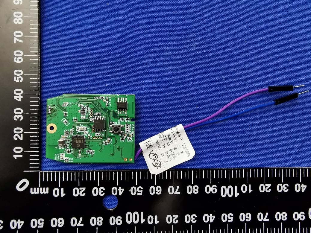
Click to zoom
Application Details
- Equipment Class
- DTS - Digital Transmission System
- Date of Grant
- Apr 21, 2020
- Application Purpose
- Original Equipment
- Date of Application
- Apr 21, 2020
- Equipment Note
- Bluetooth Sensor Module
- Frequency Range
- 2402.00000000 - 2480.00000000
- Company
- Whirlpool Corporation
- Country
- United States
Documents & Files
Document Text
Text extracted from the exhibit documents filed with the FCC. Open a document above to read the original.
Users Manual
Whirlpool Corporation ▪ 2000 M-63 ▪ Benton Harbor, MI 49022 Bluetooth Sensor Module ALTCHBSM01 (FCC ID: A5UALTCHBSM01) USER GUIDE Rev 1.0Page 1 Whirlpool Corporation ▪ 2000 M-63 ▪ Benton Harbor, MI 49022 Contents Introduction3 Purpose and scope3 Revision History3 Module Overview4 Module Application4 Major Part Details for the PCB5 Compliance Limits5 Module Features and Operation5 FCC Compliance Notices5 OEM Responsibilities to comply with FCC Regulations6 End Product Labelling6 Contact Detail7 Rev 1.0Page 2 Whirlpool Corporation ▪ 2000 M-63 ▪ Benton Harbor, MI 49022 1Introduction 1.1Purpose and scope ThepurposeofthisdocumentistoprovidedetailsregardingtheuseoftheBluetoothSensor Module.Thisdocumentalsodescribestheapplicationandoperationofit.Moreover,it declares the FCC compliance notices, too. 1.2Revision History Date Change Description Revision 2-21-2020 Release to Altran 1.0 2-21-2020 Updated FCC ID and communication standard statement 1.1 Rev 1.0Page 3 Whirlpool Corporation ▪ 2000 M-63 ▪ Benton Harbor, MI 49022 2Module Overview 2.1Module Application TheBluetoothSensorModuleistheplatformwhichwillbeusedacrossdifferentapplications based on an nRF52 Bluetooth Radio and XR871 sensor capture microcontroller. TheBluetoothSensorModuleisaBluetooth®5,2.4GHztransceiver,utilizingBLE2Mbit mode. It captures data using an attached sensor and transmits them over bluetooth. TheBluetoothSensorModulewillbepackagedinasmallenclosure(nomorethan 500cm^3)includingbatteriestopowerthedevice.Thedevicewillbeplacedinlocations appropriatetothesensorsattachedtothebluetoothmoduletoobtainusefuldataforthe consumer. Rev 1.0Page 4 Whirlpool Corporation ▪ 2000 M-63 ▪ Benton Harbor, MI 49022 2.2Major Part Details for the PCB The Bluetooth Sensor Module consists of the following major components: -nRF52840 -XR871 -SPI NOR Flash Module -DC-DC Boost Converter -Ambient Light Sensor -PIR - Passive Infrared Sensor -Onboard Chip Antenna -Connector for attaching sensor flex cable. -Solder points for battery power source wires. 2.3 Compliance Limits TheregistervalueusedforFCCcomplianceismaximumvalueandcannotbeincreasedby end user. The RF Output Power configuration is not accessible to End User. Rev 1.0Page 5 Whirlpool Corporation ▪ 2000 M-63 ▪ Benton Harbor, MI 49022 2.4Module Features and Operation TheBluetoothSensorModuleintendedtooperatewith2xAAbatteries(nominal1.5V) attached to onboard boost power supply of typical voltage 3.3VDC. 3FCC Compliance Notices FCC ID: A5UALTCHBSM01 This rebel module complies with Part 15 of the FCC Rules. The Operation is subject to the following two conditions: 1.This device may not cause harmful interference, and 2.Thisdevicemustacceptanyinterferencereceived,includingInterferencethatmay cause undesired operation. UnderFCCregulations,thisradiotransmittermayonlyoperateusinganantennaofatype andmaximum(orlesser)gainapprovedforthetransmitterbyFCC.Toreducepotentialradio interferencetootherusers,theantennatypeanditsgainshouldbesochosenthatthe equivalentisotopicallyradiatedpower(e.i.r.p.)isnotmorethanthatnecessaryforsuccessful communication.TheradiotransmitterFCC:A5UALTCHBSM01hasbeenapprovedbyFCC to operate with the on board antenna. FCC Caution!!! ●ChangesormodificationsnotexpresslyapprovedbyWhirlpoolCorporationcould void the user’s authority to operate the equipment. Part 15B compliance statements for digital devices: Note:ThisequipmenthasbeentestedandfoundtocomplywiththelimitsforaClassB digitaldevice,pursuanttoPart15oftheFCCRules.Theselimitsaredesignedtoprovide reasonableprotectionagainstharmfulinterferenceinaresidentialinstallation.This equipmentgeneratesusesandcanradiateradiofrequencyenergyand,ifnotinstalledand usedinaccordancewiththeinstructions,maycauseharmfulinterferencetoradio communications.However,thereisnoguaranteethatinterferencewillnotoccurina particularinstallation.Ifthisequipmentdoescauseharmfulinterferencetoradioortelevision reception,whichcanbedeterminedbyturningtheequipmentoffandon,theuseris encouraged to try to correct the interference by one of the following measures: •Reorient or relocate the receiving antenna. •Increase the separation between the equipment and receiver. Rev 1.0Page 6 Whirlpool Corporation ▪ 2000 M-63 ▪ Benton Harbor, MI 49022 •Connecttheequipmentintoanoutletonacircuitdifferentfromthattowhichthe receiver is connected. •Consult the dealer or an experienced radio/TV technician for help. •Thisdeviceanditsantenna(s)mustnotbeco-locatedoroperatinginconjunctionwith any other antenna or transmitter. The SAR statement ThisequipmentcomplieswithFCCradiationexposurelimitssetforthforanuncontrolled environment.Thisequipmentshouldbeinstalledandoperatedwithminimumdistanceof20 cmbetweentheradiatorandyourbody.Thistransmittermustnotbeco-locatedoroperating in conjunction with any other antenna or transmitter. 3.1OEM Responsibilities to comply with FCC Regulations The Bluetooth Sensor Module have been certified for integration into products only by OEM integrators under the following condition: 1. The transmitter module must not be co-located or operating in conjunction with any other antenna or transmitter. As long as the condition above are met, further transmitter testing will not be required. However, the OEM integrator is still responsible for testing their end-product for any additional compliance requirements required with this module installed (for example, digital device emissions, PC peripheral requirements, etc.). IMPORTANT NOTE: In the event that these conditions cannot be met (for certain configurations or co-location with another transmitter), then the FCC authorizations are no longer considered valid and the FCC ID cannot be used on the final product. In these circumstances, the OEM integrator will be responsible for re-evaluating the end product (including the transmitter) and obtaining a separate FCC authorization. 3.2End Product Labelling The Bluetooth Sensor Modules are labelled with FCC ID. If the FCC ID is not visible when the module is…
Text truncated - open the document above for the full version.
Cover Letter(s)
Modular Approval Request FCC(KDB 996369 D01 & Part 15.212) FCC ID: A5UALTCHBSM01 Items to be covered bySingle modular transmitters. Answer from applicant 1. The modular transmitter must have its own RF shielding.Yes 2. The modular transmitter must have buffered modulation/data inputs (if such inputs are provided) to ensure that the module will comply with Part 15 requirements under conditions of excessive data rates or over-modulation. Yes 3. The modular transmitter must have its own power supply regulation.Yes 4. The modular transmitter must comply with the antenna requirements of Section 15.203 and 15.204(b)(c). The antenna must either be permanently attached or employ a “unique” antenna coupler (at all connections between the module and the antenna, including the cable). Yes 5. The modular transmitter must be tested in a stand-alone configuration, i.e., the module must not be inside another device during testing. This is intended to demonstrate that the module is capable of complying with Part 15 emission limits regardless of the device into which it is eventually installed. Yes 6.The modular transmitter must be equipped with either a permanently affixed label or must be capable of electronically displaying its FCC identification number in accordance with 15.212 (a)(1)(vi)(A)/(B). Yes 7.The modular transmitter must comply with any specific rule or operating requirements applicable to the transmitter and the manufacturer must provide adequate instructions along with the module to explain any such requirements. A copy of these instructions must be included in the application for equipment authorization. For example, there are very strict operational and timing requirements that must be met before a transmitter is authorized for operation under Section 15.231. For instance, data transmission is prohibited, except for operation under Section 15.231(e), in which case there are separate field strength level and timing requirements. Compliance with these requirements must be assured. Yes 8. The modular transmitter must comply with any applicable RF exposure requirements. For example, FCC Rules in Sections 1.1310, 2.1091, 2.1093, and specific Sections of Part 15, including 15.319(i), 15.407(f), 15.253(f) and 15.255(g), require that Unlicensed PCS, UNII and millimeter wave devices perform routine environmental evaluation for RF Exposure to demonstrate compliance. In addition, spread spectrum transmitters operating under Section 15.247 are required to address RF Exposure compliance. Modular transmitters approved under other Sections of Part 15, when necessary, may also need to address certain RF Exposure concerns, typically by providing specific installation and operating instructions for users, installers and other interested parties to ensure compliance. Yes Items to be covered by Split modular transmitters. Answer from applicant 1. The modular transmitter must comply with all requirements of a single modular transmitter except for items (1) & (5) of the above single modular approval requirements. 2. Only the radio front end must be shielded. The physical crystal and tuning capacitors may be located external to the shielded radio elements. The interface between the split sections of the modular system must be digital with a minimum signalling amplitude of 150 mV peak-to-peak. 3. Control information and other data may be exchanged between the transmitter control elements and radio front end. 4. The sections of a split modular transmitter must be tested installed in a host device(s) similar to that which is representative of the platform(s) intended for use. 5. Manufacturers must ensure that only transmitter control elements and radio front end components that have been approved together are capable of operating together. The transmitter module must not operate unless it has verified that the installed transmitter control elements and radio front end have been authorized together. Manufacturers may use means including, but not limited to, coding in hardware and electronic signatures in software to meet these requirements, and must describe the methods in their application for equipment authorization. Note: A limited modular approval (LMA) may be granted forsingleorsplitmodular transmitters that comply partially with the requirements above. Name and surname of applicant (or authorizedrepresentative): Jason W Schmidt Date: __2020-4-17_______Signature:
External Photos
Annex No.: BL-SZ2020078-AW 1 / 4 EUT EXTERNAL PHOTOS FRONT VIEW OF EUT REAR VIEW OF EUT Annex No.: BL-SZ2020078-AW 2 / 4 LEFT SIDE VIEW OF EUT RIGHT SIDE OF EUT Annex No.: BL-SZ2020078-AW 3 / 4 TOP VIEW OF EUT BOTTOM VIEW OF EUT Annex No.: BL-SZ2020078-AW 4 / 4 Accessory-Camera
ID Label/Location Info
Label-location WHIRLPOOL CORP. MODEL: ALTCHBSM01 FCC ID: A5UALTCHBSM01
Internal Photos
Annex No.: BL-SZ2020078-AI 1 / 2 EUT INTERNAL PHOTOS EUT UNCOVER VIEW MAIN BOARD TOP VIEW Ceramic Antenna RF Chip Annex No.: BL-SZ2020078-AI 2 / 2 MAIN BOARD REAR VIEW
RF Exposure Info
RF Exposure Evaluation for FCC ID: A5UALTCHBSM01 Refer user manual this device is a Bluetooth Sensor Module, and this device was designed used in Mobile devices that the minimum distance between human’s body is 20cm. Based on the 47CFR 2.1091, this device belongs to Mobile device. The definition of the category as following: Mobile Derives: CFR Title 47 §2.1091(b) (b) For purposes of this section, a mobile device is defined as a transmitting device designed to be used in other than fixed locations and to generally be used in such a way that a separation distance of at least 20 centimeters is normally maintained between the transmitter’s radiating structure(s) and the body of the user or nearby persons. FCC KDB 447498 D01 General RF Exposure Guidance v06 Limit Devices operating in standalone mobile exposure conditions may contain a single transmitter or multiple transmitters that do not transmit simultaneously. A minimum test separation distance ≥ 20 cm is required between the antenna and radiating structures of the device and nearby persons to apply mobile device exposure limits. The distance must be fully supported by the operating and installation configurations of the transmitter and its antenna(s), according to the source-based time-averaged maximum power requirements of § 2.1091(d)(2). In cases where cable losses or other attenuations are applied to determine compliance, the most conservative operating configurations and exposure conditions must be evaluated. The minimum test separation distance required for a device to comply with mobile exposure conditions must be clearly identified in the installation and operating instructions, for all installation and exposure conditions, to enable users and installers to comply with RF exposure requirements. For mobile devices that have the potential to operate in portable device exposure conditions, similar to the configurations described in § 2.1091(d)(4), a KDB inquiry is required to determine the SAR test requirements for demonstrating compliance. When the categorical exclusion provision of § 2.1091(c) applies, the minimum test separation distance may be estimated, when applicable, by simple calculations according to plane-wave equivalent conditions, to ensure the transmitter and its antenna(s) can operate in manners that meet or exceed the estimated distance. The source-based time-averaged maximum radiated power, according to the maximum antenna gain, must be applied to calculate the field strength and power density required to establish the minimum test separation distance. When the estimated test separation distance becomes overly conservative and does not support compliance, MPE measurement or computational modeling may be used to determine the required minimum separation distance. According to FCC Part 1.1307, systems operating under the provisions of this section shall be operated in a manner the ensures that the public is not exposed to radio frequency energy level in excess of the commission’s guidelines. Limits for General Population/ Uncontrolled Exposure Frequency Range (MHz) Electric Field Strength(E)(V/m) Magnetic Field Strength (H)(A/m) Power Density (S)(mW/cm 2 ) 0.3-1.34 614 1.63 (100)* 1.34-30 824/f 2.19/f (180/f2)* 30-300 27.5 0.073 0.2 300-1500 f/1500 1500-100,000 1.0 MPE calculation formula Where: S = power density P = output power (mW) G = power gain of the antenna in the direction of interest relative to an isotropic radiator R = Separation distance between radiator and human body (cm) Test data BLUETOOTH Mode GFSK BLE 1Mbps BLE 2Mbps Peak Power (dBm) 4.86 4.88 Note: This report listed the worst case peak power value, please refer to RF test report for more details. Test result Evolution mode Maximum peak output power (dBm) Antenna Gain (typical) (dBi): Total Power (mw) Distance (cm) Limit of Power Density (mW/cm²) Power Density (mW/cm²) Verdict Bluetooth 5.00 0.5 3.55 20 1 7.06*10 -4 Pass Note: 1. The Bluetooth Sensor Module work frequency range used is 2400 MHz ~ 2483.5 MHz, the result close to the limit by the above formula. Conclusion: RF exposure Evaluation Results: Compliance
Test Report
Report No.: BL-SZ2020078-601 2 / 65 Revision History Version Issue Date Revisions Content Rev. 01 Apr. 16, 2020 Initial Issue TABLE OF CONTENTS 1 ADMINISTRATIVE DATA (GENERAL INFORMATION) ........................................................................ 5 1.1 Identification of the Testing Laboratory ..................................................................................... 5 1.2 Identification of the Responsible Testing Location .................................................................... 5 1.3 Laboratory Condition ................................................................................................................ 5 1.4 Announce ................................................................................................................................. 5 2 PRODUCT INFORMATION ................................................................................................................... 6 2.1 Applicant Information ................................................................................................................ 6 2.2 Manufacturer Information .......................................................................................................... 6 2.3 Factory Information ................................................................................................................... 6 2.4 General Description for Equipment under Test (EUT) ............................................................... 6 2.5 Technical Information ............................................................................................................... 7 2.6 Additional Instructions .............................................................................................................. 8 3 SUMMARY OF TEST RESULTS ........................................................................................................... 9 3.1 Test Standards ......................................................................................................................... 9 3.2 Verdict ...................................................................................................................................... 9 4 GENERAL TEST CONFIGURATIONS ................................................................................................ 10 4.1 Test Environments .................................................................................................................. 10 4.2 Test Equipment List ................................................................................................................ 10 4.3 Measurement Uncertainty ....................................................................................................... 11 4.4 Description of Test Setup ....................................................................................................... 12 4.4.1 For Antenna Port Test ............................................................................................................ 12 4.4.2 For AC Power Supply Port Test .............................................................................................. 12 4.4.3 For Radiated Test (Below 30 MHz) ......................................................................................... 13 4.4.4 For Radiated Test (30 MHz-1 GHz) ........................................................................................ 13 4.4.5 For Radiated Test (Above 1 GHz) .......................................................................................... 14 4.5 Measurement Results Explanation Example ........................................................................... 15 4.5.1 For conducted test items: ....................................................................................................... 15 Report No.: BL-SZ2020078-601 3 / 65 4.5.2 For radiated band edges and spurious emission test: ............................................................. 15 5 TEST ITEMS ....................................................................................................................................... 16 5.1 Antenna Requirements ........................................................................................................... 16 5.1.1 Relevant Standards ................................................................................................................ 16 5.1.2 Antenna Anti-Replacement Construction ................................................................................ 16 5.1.3 Antenna Gain ......................................................................................................................... 16 5.2 Output Power ......................................................................................................................... 17 5.2.1 Test Limit ................................................................................................................................ 17 5.2.2 Test Setup .............................................................................................................................. 17 5.2.3 Test Procedure ....................................................................................................................... 17 5.2.4 Test Result ............................................................................................................................. 18 5.3 Occupied Bandwidth ............................................................................................................... 19 5.3.1 Limit........................................................................................................................................ 19 5.3.2 Test Setup .............................................................................................................................. 19 5.3.3 Test Procedure ....................................................................................................................... 19 5.3.4 Test Result ..…
Text truncated - open the document above for the full version.
Test Setup Photos
Annex No.: BL-SZ2020078-AR TESTSETUPPHOTOS 1 RadiatedTestPhoto Below 30 MHz 30 MHz-1 GHz Annex No.: BL-SZ2020078-AR Close-Up Above 1GHz Annex No.: BL-SZ2020078-AR Close-Up 2 ConductedEmissions Test Photo 1 Annex No.: BL-SZ2020078-AR Test Photo 2 3 ConductedTestPhoto Conducted Test
Contact Information
Applicant
Paul A Friis(Managing Engineer, Regulatory Affairs)
Test Firm
Shenzhen BALUN Technology Co., Ltd.Hanson Lin
[email protected]86-755-66833830
Technical Specifications
| # | Rule Parts | Frequency Range | Power Output |
|---|---|---|---|
| 1 | 15C | 2.40 GHz - 2.48 GHz | 3.08 mW |
Other Applications from Whirlpool Corporation
A5UTTIVNWMT02
Nov 27, 2025KitchenAid Smart Thermometer
Equipment Class
DTS - Digital Transmission System
A5UWICHI201
May 06, 2020Indigo-2 WiFi Module
Equipment Class
DSS - Part 15 Spread Spectrum Transmitter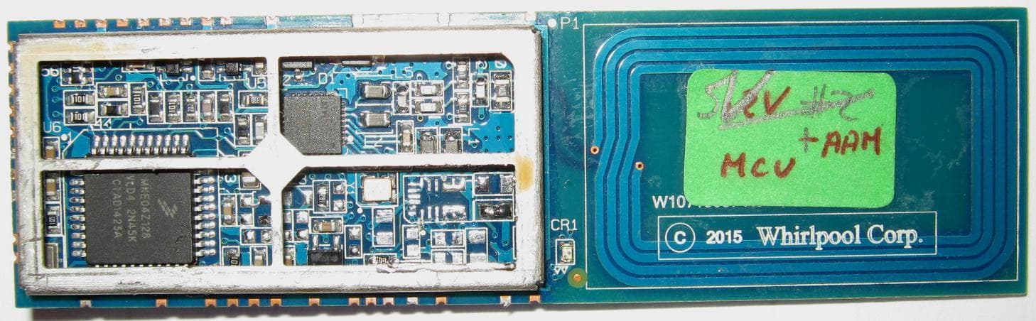
A5UXPNFC
Jun 25, 2015NFC Module
Equipment Class
DXT - Part 15 Low Power Transceiver, Rx Verified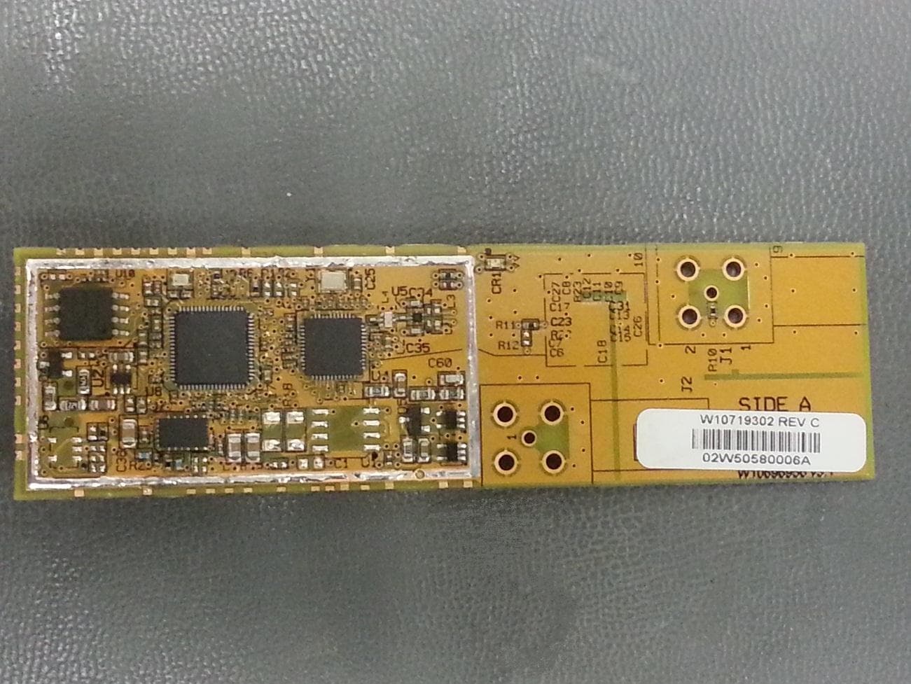
A5UXPWG3
Mar 26, 2015WiFi Gen3 Module
Equipment Class
DTS - Digital Transmission System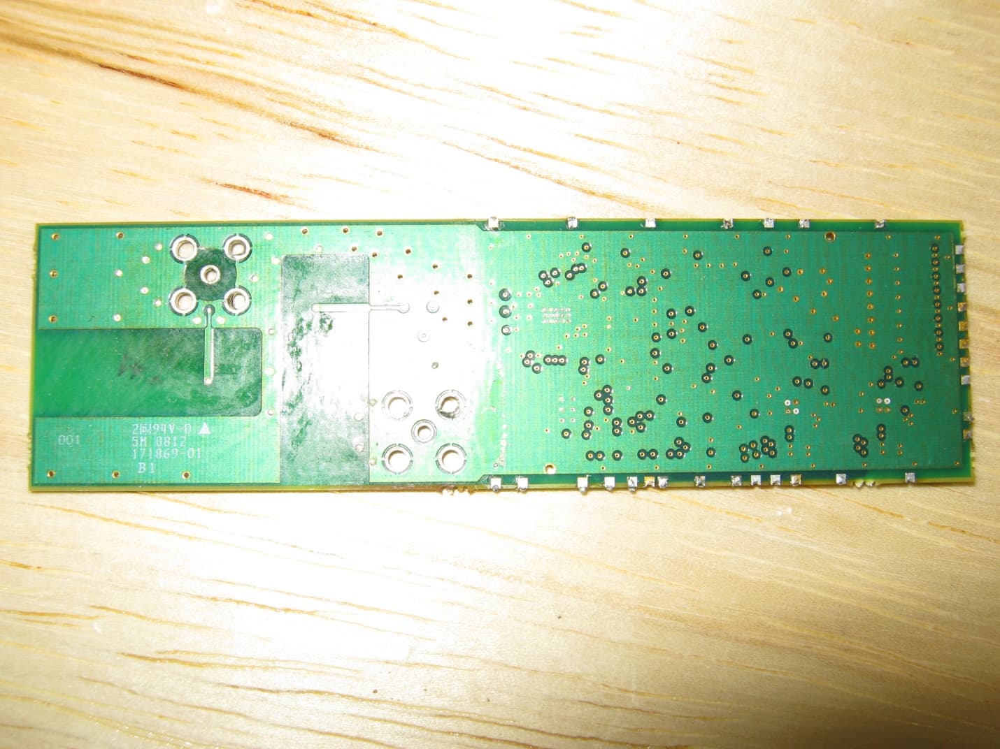
A5UXPCP
Mar 25, 2013Appliance Modular Transmitter
Equipment Class
DTS - Digital Transmission System