A6RMCX2000ADigital Audio Server with 802.11b/g transmitter
Yamaha Corporation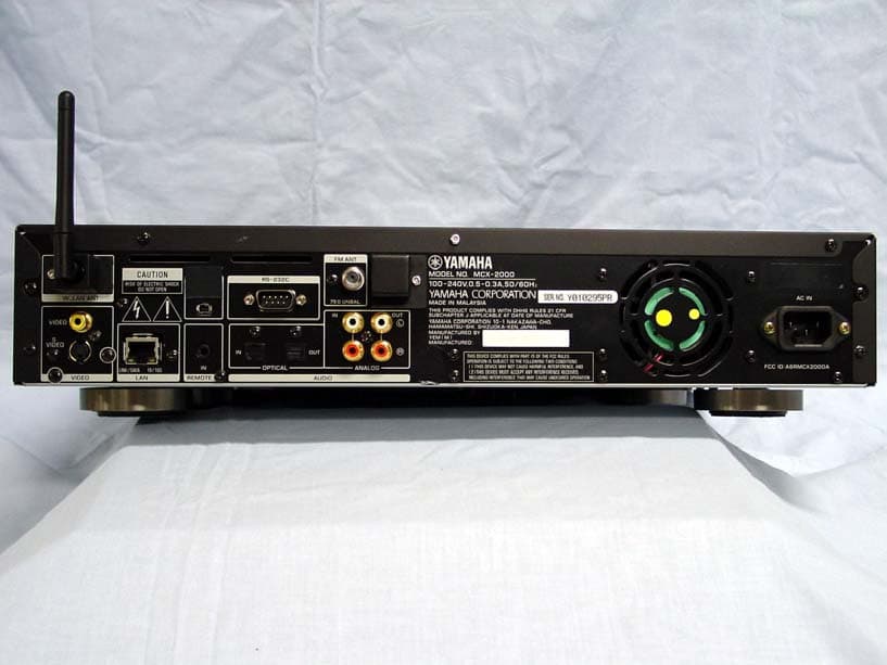
Click to zoom
Application Details
- Equipment Class
- DTS - Digital Transmission System
- Date of Grant
- Sep 12, 2005
- Application Purpose
- Original Equipment
- Date of Application
- Sep 12, 2005
- Equipment Note
- Digital Audio Server with 802.11b/g transmitter
- Frequency Range
- 2417.00000000 - 2457.00000000
- Company
- Yamaha Corporation
- Country
- Japan
Documents & Files
Document Text
Text extracted from the exhibit documents filed with the FCC. Open a document above to read the original.
Users Manual
IMPORTANT SAFETY INSTRUCTIONS •Explanation of Graphical Symbols The lightning flash with arrowhead symbol, within an equilateral triangle, is intended to alert you to the presence of uninsulated “dangerous voltage” within the product’s enclosure that may be of sufficient magnitude to constitute a risk of electric shock to persons. The exclamation point within an equilateral triangle is intended to alert you to the presence of important operating and maintenance (servicing) instructions in the literature accompanying the appliance. 1Read these instructions. 2Keep these instructions. 3Heed all warnings. 4Follow all instructions. 5Do not use this apparatus near water. 6Clean only with dry cloth. 7Do not block any ventilation openings. Install in accordance with the manufacturer’s instructions. 8Do not install near any heat sources such as radiators, heat registers, stoves, or other apparatus (including amplifiers) that produce heat. 9Do not defeat the safety purpose of the polarized or grounding-type plug. A polarized plug has two blades with one wider than the other. A grounding type plug has two blades and a third grounding prong. The wide blade or the third prong are provided for your safety. If the provided plug does not fit into your outlet, consult an electrician for replacement of the obsolete outlet. 10Protect the power cord from being walked on or pinched particularly at plugs, convenience receptacles, and the point where they exit from the apparatus. 11Only use attachments/accessories specified by the manufacturer. 12Use only with the cart, stand, tripod, bracket, or table specified by the manufacturer, or sold with the apparatus. When a cart is used, use caution when moving the cart/apparatus combination to avoid injury from tip-over. 13Unplug this apparatus during lightning storms or when unused for long periods of time. 14Refer all servicing to qualified service personnel. Servicing is required when the apparatus has been damaged in any way, such as power-supply cord or plug is damaged, liquid has been spilled or objects have fallen into the apparatus, the apparatus has been exposed to rain or moisture, does not operate normally, or has been dropped. We Want You Listening For A Lifetime YAMAHA and the Electronic Industries Association’s Consumer Electronics Group want you to get the most out of your equipment by playing it at a safe level. One that lets the sound come through loud and clear without annoying blaring or distortion — and, most importantly, without affecting your sensitive hearing. Since hearing damage from loud sounds is often undetectable until it is too late, YAMAHA and the Electronic Industries Association’s Consumer Electronics Group recommend you to avoid prolonged exposure from excessive volume levels. CAUTION: TO REDUCE THE RISK OF ELECTRIC SHOCK, DO NOT REMOVE COVER (OR BACK). NO USER-SERVICEABLE PARTS INSIDE. REFER SERVICING TO QUALIFIED SERVICE PERSONNEL. CAUTION RISK OF ELECTRIC SHOCK DO NOT OPEN (DECLARATION OF CONFORMITY PROCEDURE) Responsible Party: Address: Telephone: Fax: Type of Equipment: Model Name: Yamaha Electronics Corporation, U.S.A. 6660 Orangethorpe Avenue Buena Park, CA 90620 714-522-9105 714-670-0108 Digital Audio Server MCX-2000 This device complies with Part 15 of the FCC Rules. Operation is subject to the following conditions: 1) this device may not cause harmful interference, and 2) this device must accept any interference received including interference that may cause undesired operation. See the “TROUBLESHOOTING” section at the end of this manual if interference to radio reception is suspected. COMPLIANCE INFORMATION STATEMENT FCC INFORMATION (for US customers only) 1IMPORTANT NOTICE: DO NOT MODIFY THIS UNIT! This product, when installed as indicated in the instructions contained in this manual, meets FCC requirements. Modifications not expressly approved by Yamaha may void your authority, granted by the FCC, to use the product. 2IMPORTANT: When connecting this product to accessories and/ or another product use only high quality shielded cables. Cable/s supplied with this product MUST be used. Follow all installation instructions. Failure to follow instructions could void your FCC authorization to use this product in the USA. 3NOTE: This product has been tested and found to comply with the requirements listed in FCC Regulations, Part 15 for Class “B” digital devices. Compliance with these requirements provides a reasonable level of assurance that your use of this product in a residential environment will not result in harmful interference with other electronic devices. This equipment generates/uses radio frequencies and, if not installed and used according to the instructions found in the users manual, may cause interference harmful to the operation of other electronic devices. Compliance with FCC regulations does not guarantee that interference will not occur in all installations. If this product is found to be the source of interference, which can be determined by turning the unit “OFF” and “ON”, please try to eliminate the problem by using one of the following measures: Relocate either this product or the device that is being affected by the interference. Utilize power outlets that are on different branch (circuit breaker or fuse) circuits or install AC line filter/s. In the case of radio or TV interference, relocate/reorient the antenna. If the antenna lead-in is 300 ohm ribbon lead, change the lead-in to coaxial type cable. If these corrective measures do not produce satisfactory results, please contact the local retailer authorized to distribute this type of product. If you can not locate the appropriate retailer, please contact Yamaha Electronics Corporation, U.S.A. 6660 Orangethorpe Avenue, Buena Park, CA 90620. The above statements apply ONLY to those products distributed by Yamaha Corporation of America or its subsidiaries. •To assure the finest performance, please read this manual carefully. Keep it in a safe place for f…
Text truncated - open the document above for the full version.
External Photos
External Photo YAMAHA CORPORATION FCC ID: A6RMCX2000A IC Number:740B-MCX2000A front Back External Photo YAMAHA CORPORATION FCC ID: A6RMCX2000A IC Number:740B-MCX2000A Top Bottom
Internal Photos
Internal Photo YAMAHA CORPORATION FCC ID: A6RMCX2000A IC Number: 740B-MCX2000A Module location Module location enlarged Internal Photo YAMAHA CORPORATION FCC ID: A6RMCX2000A IC Number: 740B-MCX2000A Module (Solder side) Module (Comp side with shield) Internal Photo YAMAHA CORPORATION FCC ID: A6RMCX2000A IC Number: 740B-MCX2000A Module (Comp side without shield) Metal plate Antenna Internal Photo YAMAHA CORPORATION FCC ID: A6RMCX2000A IC Number: 740B-MCX2000A Metal plate antenna enlarged
Operational Description
1 General Specification For Transmitter Information on the equipment Equipment identification FCC ID : A6RMCX2000A , IC No. : 740B-MCX2000A Intended use / Purpose of the equipment Transmission and reception of music data Brand Name YAMAHA Model (Type designation) MCX-2000 Transmitter Receiver ■ Transceiver Mode of Operation Simplex ■ Half/Full Frequency of operation 2417 – 2457MHz Lower limit 802.11b/g 2400 MHz Upper limit 802.11b/g 2483.5MHz Frequency band Band width 802.11b/g 17MHz Maximum transmitter output power 11b:16dBm / 11g:20dBm Number of channels and channel spacing 802.11b/g : 2-10ch , 5MHz Modulation BPSK , QPSK , CCK , OFDM Information on antenna Metal plate antenna , λ/2 dipole antenna Method of Frequency Generation ■ Crystal ■ Synthesizer Other ( ) Duty cycle (if applicable) Very High(Up to 100%) Transmission time per 1 cycle Intermission time per 1 cycle Continuous time including intermissions Power supply AC 120V / 60Hz Antenna gain Metal plate antenna : 3.0dBi , λ/2 dipole antenna : 2.15dBi Operating temperature range +5 ~ +35 degree.C. Designation of Emission (ITU code) G1D Channel Access Protocol (if applicable) MCX-2000 W_LAN setup utility
RF Exposure Info
UL Apex Co., Ltd. Head Office EMC Lab. 4383-326 Asama-cho, Ise-shi, Mie-ken 516-0021 JAPAN Telephone : +81 596 24 8116 Facsimile : +81 596 24 8124 Applicant: YAMAHA CORPORATION T ype of Equipment : Digital Audio Server Model No. : MCX-2000 FCC ID: A6RMCX2000A RF Exposure Calculations: The following information provides the minimum separation distance for the highest gain antenna provided with the “MCX-2000“ as calculated from FCC OET Bulletin 65 Appendix A, Table (B) Limits for General Population / Uncontrolled Exposure. This calculation is based on the highest EIRP possible from the system, considering maximum power and antenna gain, and considering a 1.0mW/cm^2 uncontrolled exposure limit. The Friis formula used was: S = (P * G) / (4* π * r 2 ) Where P = 106.17 mW (Maximum peak output power) G = 2.00 Numerical Antenna gain; equal 3.00dBi r =20.0 cm For: MCX-2000S = 0.04214 mW/cm 2 No. : 25IE0258-HO RF Exposure / SAR Statement
Test Report
Test report No. : 25IE0258-HO-1a Page : 2 of 101 Issued date : August 8, 2005 Revised date : August 19, 2005 FCC ID : A6RMCX2000A UL Apex Co., Ltd. Head Office EMC Lab. 4383-326 Asama-cho, Ise-shi, Mie-ken 516-0021 JAPAN Telephone : +81 596 24 8116 Facsimile : +81 596 24 8124 MF060b(01.06.05) CONTENTS PAGE SECTION 1: Client information ......................................................................................................... 3 SECTION 2: Equipment under test (E.U.T.)..................................................................................... 3 SECTION 3: Test specification, procedures & results...................................................................... 5 SECTION 4: Operation of E.U.T. during testing .............................................................................. 7 SECTION 5: Conducted Emission.................................................................................................... 10 SECTION 6: Spurious Emission ....................................................................................................... 11 SECTION 7: 6dB Bandwidth ............................................................................................................ 12 SECTION 8: Maximum Peak Output Power .................................................................................. 12 SECTION 9: Peak Power Density..................................................................................................... 12 APPENDIX 1: Photographs of test setup .........................................................................................13 Conducted Emission .............................................................................................................................. 13 Spurious Emission (Radiated)............................................................................................................... 14 Worst Case Main Antenna Position (Y-axis:Horizontal / X-axis:Vertical) ...................................... 15 APPENDIX 2:Test instruments ......................................................................................................... 16 APPENDIX 3: Data of EMI test......................................................................................................... 17 Conducted Emission .............................................................................................................................. 17 6dB Bandwidth ....................................................................................................................................... 26 Maximum Peak OutPut Power ............................................................................................................. 29 Radiated Spurious Emission(below 1GHz) ..........................................................................................32 Radiated Spurious Emission(above 1GHz ) .........................................................................................44 Conducted Spurious Emission .............................................................................................................. 90 Conducted emission Band Edge compliance ....................................................................................... 96 Power Density ......................................................................................................................................... 97 99%Occupied Bandwidth.................................................................................................................... 100 Test report No. : 25IE0258-HO-1a Page : 3 of 101 Issued date : August 8, 2005 Revised date : August 19, 2005 FCC ID : A6RMCX2000A UL Apex Co., Ltd. Head Office EMC Lab. 4383-326 Asama-cho, Ise-shi, Mie-ken 516-0021 JAPAN Telephone : +81 596 24 8116 Facsimile : +81 596 24 8124 MF060b(01.06.05) SECTION 1: Client information Company Name : YAMAHA CORPORATION Brand Name : YAMAHA Address : 10-1 Nakazawa-cho, Hamamatsu-shi, Shizuoka 430-8650 Japan Telephone Number : +81-53-460-3325 Facsimile Number : +81-53-471-1147 Contact Person : Hiroshi Yamazaki SECTION 2: Equipment under test (E.U.T.) 2.1 Identification of E.U.T. Type of Equipment : Digital Audio Server Model No. : MCX-2000 Serial No. : Y010305PR Rating : AC120V / 0.53A Country of Manufacture : Malaysia Receipt Date of Sample : May 11, 2005 Condition of EUT : Engineering prototype (Not for Sale: This sample is equivalent to mass-produced items.) 2.2 Product Description Model No: MCX-2000 (referred to as the EUT in this report) is the Digital Audio Server. IEEE802.11b IEEE802.11g Wireless LAN Clock frequency in the system Wireless LAN Module:40MHz Server : CPU 25MHz Sub CPU 20MHz Digital Radio IC 45.16MHz Feature of EUT ・ Audio player function MCX-2000 can play music CD,MP3(CD-ROM),the audio signal inputted from the outside, the radio program by built-in FM tuner. ・ Audio recorder function Music CD,MP3(CD-ROM),the audio signal inputted from the outside,the radio program by built-in FM tuner can be recorded to a built-in hard disk drive. ・ CD recorder function The original music CD can be made combining the music in archives. ・ Music distribution function MCX-2000 can distribute to a maximum of 15 sets clients which installed in each room through the Music CAST network of wired/wireless LAN. Test report No. : 25IE0258-HO-1a Page : 4 of 101 Issued date : August 8, 2005 Revised date : August 19, 2005 FCC ID : A6RMCX2000A UL Apex Co., Ltd. Head Office EMC Lab. 4383-326 Asama-cho, Ise-shi, Mie-ken 516-0021 JAPAN Telephone : +81 596 24 8116 Facsimile : +81 596 24 8124 MF060b(01.06.05) IEEE802.11b IEEE802.11g Wireless LAN Equipment Type Transceiver Frequency band Lower limit 2400MHz Upper limit 2483.5MHz Frequency of Operation 2417MHz to 2457MHz Bandwidth & Channel spacing 26MHz & 5MHz Type of Modulation DSSS, OFDM Antenna Type Main antenna : lambda/2 Dipole Antenna Sub Antenna : Metal Plate Antenna Antenna Connector Type Main antenna : Reverse…
Text truncated - open the document above for the full version.
Test Setup Photos
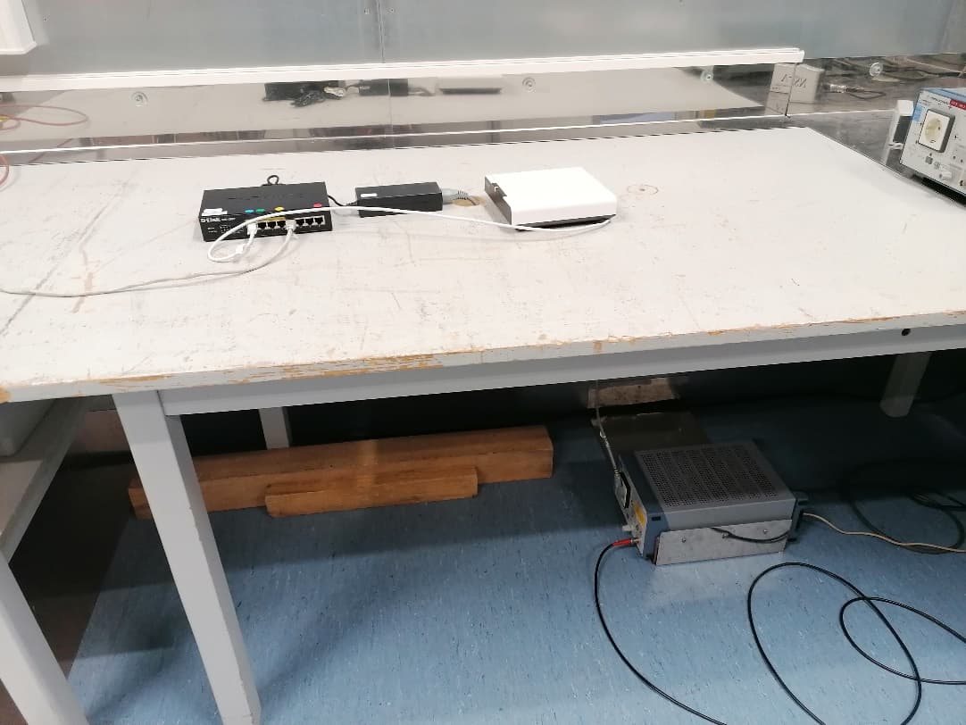
Test report No. : 25IE0258-HO-1 Page : 13 of 101 Issued date : August 8, 2005 FCC ID : A6RMCX2000A UL Apex Co., Ltd. Head Office EMC Lab. 4383-326 Asama-cho, Ise-shi, Mie-ken 516-0021 JAPAN Telephone : +81 596 24 8116 Facsimile : +81 596 24 8124 MF060b(01.06.05) APPENDIX 1: Photographs of test setup Conducted Emission Front Side Test report No. : 25IE0258-HO-1 Page : 14 of 101 Issued date : August 8, 2005 FCC ID : A6RMCX2000A UL Apex Co., Ltd. Head Office EMC Lab. 4383-326 Asama-cho, Ise-shi, Mie-ken 516-0021 JAPAN Telephone : +81 596 24 8116 Facsimile : +81 596 24 8124 MF060b(01.06.05) Spurious Emission (Radiated) Front Rear Test report No. : 25IE0258-HO-1 Page : 15 of 101 Issued date : August 8, 2005 FCC ID : A6RMCX2000A UL Apex Co., Ltd. Head Office EMC Lab. 4383-326 Asama-cho, Ise-shi, Mie-ken 516-0021 JAPAN Telephone : +81 596 24 8116 Facsimile : +81 596 24 8124 MF060b(01.06.05) Worst Case Main Antenna Position (Y-axis:Horizontal / X-axis:Vertical) X-axis Y-axis Z-axis
Contact Information
Applicant
Kenji Kawasaki
Technical Contact
UL Apex Co., LtdNaoki Sakamoto
[email protected]+81-596-24-8116
4383-326 Asama-cho · Ise-shi, Mie-ken · Japan
Non-Technical Contact
UL Apex Co., LtdYoshiko Mizuta
[email protected]+81-596-24-8116
Test Firm
UL Japan, IncMitsuru Fujimura
Technical Specifications
| # | Rule Parts | Frequency Range | Power Output |
|---|---|---|---|
| 1 | 15C | 2.42 GHz - 2.46 GHz | 106.00 mW |
Other Applications from Yamaha Corporation
A6RRMWAP16
Feb 09, 2021Microphone Accesspoint
Equipment Class
PUB - Part 15 Unlicensed PCS Base Station
A6RRMWCH8
Feb 09, 2021Microphone Charger
Equipment Class
PUB - Part 15 Unlicensed PCS Base Station
A6RRMWAP8
Feb 09, 2021Microphone Accesspoint
Equipment Class
PUB - Part 15 Unlicensed PCS Base Station
A6RRMWMIC
Feb 09, 2021Wireless Microphone
Equipment Class
PUB - Part 15 Unlicensed PCS Base Station
A6RTSXN237
Feb 08, 2021Desktop Audio System
Equipment Class
DCD - Part 15 Low Power Transmitter Below 1705 kHz