A7V-SR25502001Mobile Consumer Booster
ShenZhen SolidRF Communications Co., Ltd
Click to zoom
Application Details
- Equipment Class
- B2W - Part 20 Wideband Consumer Booster (CMRS)
- Date of Grant
- Mar 02, 2015
- Application Purpose
- Original Equipment
- Date of Application
- Feb 10, 2015
- Equipment Note
- Mobile Consumer Booster
- Frequency Range
- 2110.00000000 - 2155.00000000
- Country
- China
Documents & Files
Document Text
Text extracted from the exhibit documents filed with the FCC. Open a document above to read the original.
Users Manual
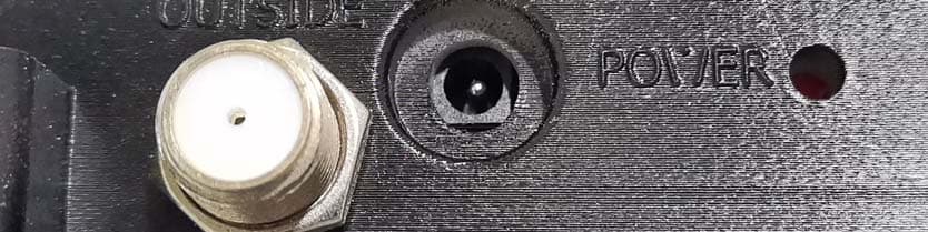
What bands and wireless providers are served with this booster? What bands and wireless providers are served with this booster?What bands and wireless providers are served with this booster? What bands and wireless providers are served with this booster? Frequenc y Bands: LTE -707(Band12, 17)/LTE-78 1(Band 13)/C ellular8 50 (Band 5)/PC S-1900 (Band2 , 25 )/AWS2100 (Ban d4). Th is e quipme nt is a mul tiband s igna l amp lifie r w hich s upports : C e llular 850 MH z , PC S 1900 MH z, AWS and 7 00 MH z for b oth AT&T an d Verizon-4G netw orks as we ll as the Sp rint 4G G-Bloc k of 1 900 MH z . So lidR F SR 255020 01 D elivers up to 50 d B of g ain and s uppo rts C D MA , GSM, E VD O, LT E, H SPA+ and WCD MA tec hno lo gies. How does it work? How does it work? How does it work? How does it work? 1. Th e outside a ntenn a rec eive s w eek s igna l fro m base s ta tion a nd se nds it to the booster th ro ugh ou ts ide cable. T he boo ster c an fil ter a nd amp lify the sign al. Th en the inside antenn a broad cas ts the improv ed sig nal to ins id e spa ce to enhance th e ce llphone s igna l. 2. When u se r’s mob ile termin al trans mits, th e boo ster a mplifies the ce llph one ’s sign al from th e in side an tenna a nd sends it to ou tside antenna throug h cab le s. Th e amplified s ig nal w ill be tra nsmit te d to the w ireless pro vide r’s tow er. T he w ho le p ro ces s of th e commu nication lin k is estab li sh ed. Why use a Booster Why use a BoosterWhy use a Booster Why use a Booster? ?? ? So meone u sing mo bile d evice s cannot con nec t to th e bas e station sign al; ex perienc es ca ll failu re , or a re u nab le to co nne ct to the in ternet. Which this o ccu rs , i t is gen erally d ue to one o f tw o re asons: 1. Lo cation of th e nea re st c ell tow e r – ce ll to w ers are situated to provid e bro ad co verag e; how eve r, th ere are many area s in w hich sign al s trength may be red uced by topo graph ic fea tu re s or b y lo cal gov ernmen t rest riction s on the he ig ht o r plac emen t of the tow ers thems elves . R u ral areas gene ra lly h ave few e r ce ll to w ers th an urban region s. 2. N atural and ma n-made obstructions – s ig nal stre ngth ca n also be n ega tive ly affe cted by trees , hil ls, b uild in gs, w eathe r, and o th er ob structions . You ma y be relativ ely clos e to a cell tow er bu t s till un able to make a c all. This often oc curs in home s and o th er bu ilding s in w hich stuc co , co ncrete or me ta l w a lls may b lo ck the s ig nal. Ea sily s olve the se problems by installing a SolidRF bo oster. Overview of installation Overview of installationOverview of installation Overview of installation 1. Selec t installation loca tion a way fro m d irec t su nlig ht, he at, w ater and p ro per ven tilation. D o N OT in stall in a se aled en closu re . 2. Before powe ring up th e Signa l Boo ster, ve ri fy th at b oth th e Outside An te nna and the In side An te nna are conne cted and che ck that all c onn ections a re tight. Note: Be careful when plugging the connectors in so as not to bend the center pins on the connectors. Warning: Warning:Warning: Warning: Connecting the Signal Booster directly to a cell phone with use of an adapter Connecting the Signal Booster directly to a cell phone with use of an adapter Connecting the Signal Booster directly to a cell phone with use of an adapter Connecting the Signal Booster directly to a cell phone with use of an adapter will damage the cell phone and/or the Signal Boos will damage the cell phone and/or the Signal Booswill damage the cell phone and/or the Signal Boos will damage the cell phone and/or the Signal Booster. te r.te r. te r. Booster function Booster functionBooster function Booster function Figure 1 Figure 1Figure 1 Figure 1 OU TS ID E :to conne ct w ith ou ts id e cab le , ou ts id e anten na. IN SID E: to co nne ct w ith inside c able, in side an tenna s. Ba nd lig hts: i t s how s th e status of in dicated b and . Flicke r mea ns the bo oster fa il on the band. Pow er light: I t ind ic ated whe ther the p ower is turn on . Signal b oos te r joint typ es:SMA \ F ME \ N Notifications NotificationsNotifications Notifications D o N OT plug in th e pow e r supply un til o utside an te nna a nd insid e antenn a are connec ted to the a mplifier. F or w ireless a mplifier, do N OT attemp t to co nnec t the amp lifier d irec tly to mobile dev ices , this can c aus e serious d amag e to b oth of amplifier a nd mob ile dev ices . F or the pu rp ose o f ve hicle use, d o N OT use a ny type o f glas s-moun t an te nna . Outside an tenna a nd insid e a ntenna must be sh ie lded fro m e ach o th er to prevent o scillatio n. U se only the p ower supply provided in this pa ck age , Or ap prove d by the SOLIDR F pow er a dap te r If the v ehicle ha s a su nro of, the ou ts id e antenna an d in side an te nna mu st b e separated fro m ea ch othe r as far as po ssible. It aims to pre ven t s elf-os cillation of the a mplifier. Before installation Before installationBefore installation Before installation C omp le te Ins talla tion D iag ra m ① : SR2 55 02 001 sig nal booster ② :Out si de antenna ③ :Insi de ante nn a ④ :P ow er adapt er Location for outsid e ant enna: R ecom mend S ati sf act or y Pr oh ibit ed Outside ante nna a nd insid e ant en na dista nc e of not less th an 5 55 5 feet. Outs ide ant e nn a Insid e an tenna Warnings and Recommendations Warnings and RecommendationsWarnings and Recommendations Warnings and Recommendations Warning: Warning:Warning: Warning: This consumer booster is for This consumer booster is for This consumer booster is for This consumer booster is for Consumer ConsumerConsumer Consumer use only. use only.use only. use only. Warning: Warning:Warning: Warning: Unauthorized antennas, cables, and/or coupling devices are prohibited Unauthorized antennas, cables, and/or coupling devices are prohibited Unauthorized antennas, cables, and/or coupling devices are prohibited Unauth…
Text truncated - open the document above for the full version.
Users Manual
What bands and wireless providers are served with this booster? What bands and wireless providers are served with this booster?What bands and wireless providers are served with this booster? What bands and wireless providers are served with this booster? Frequency Bands: LTE-707(Band12, 17)/LTE-781(Band13)/Cellular850 (Band5)/PCS-1900(Band2, 25)/AWS2100 (Band4). This equipment is a multiband signal amplifier which supports: Cellular 850 MHz, PCS 1900 MHz, AWS and 700 MHz for both AT&T and Verizon-4G networks as well as the Sprint 4G G-Block of 1900 MHz. SolidRF SR25502001 Delivers up to 50 dB of gain and supports CDMA, GSM, EVDO, LTE, HSPA+ and WCDMA technologies. How does it work? How does it work? How does it work? How does it work? 1. The outside antenna receives week signal from base station and sends it to the booster through outside cable. The booster can filter and amplify the signal. Then the inside antenna broadcasts the improved signal to inside space to enhance the cellphone signal. 2. When user’s mobile terminal transmits, the booster amplifies the cellphone’s signal from the inside antenna and sends it to outside antenna through cables. The amplified signal will be transmitted to the wireless provider’s tower. The whole process of the communication link is established. Why use a Booster Why use a BoosterWhy use a Booster Why use a Booster? ?? ? Someone using mobile devices cannot connect to the base station signal; experiences call failure, or are unable to connect to the internet. Which this occurs, it is generally due to one of two reasons: 1. Location of the nearest cell tower – cell towers are situated to provide broad coverage; however, there are many areas in which signal strength may be reduced by topographic features or by local government restrictions on the height or placement of the towers themselves. Rural areas generally have fewer cell towers than urban regions. 2. Natural and man-made obstructions – signal strength can also be negatively affected by trees, hills, buildings, weather, and other obstructions. You may be relatively close to a cell tower but still unable to make a call. This often occurs in homes and other buildings in which stucco, concrete or metal walls may block the signal. Easily solve these problems by installing a SolidRF booster. Overview of installation Overview of installationOverview of installation Overview of installation 1. Select installation location away from direct sunlight, heat, water and proper ventilation. Do NOT install in a sealed enclosure. 2. Before powering up the Signal Booster, verify that both the Outside Antenna and the Inside Antenna are connected and check that all connections are tight. Note: Be careful when plugging the connectors in so as not to bend the center pins on the connectors. Warning: Warning:Warning: Warning: Connecting the Signal Booster directly to a cell phone with use of an adapter Connecting the Signal Booster directly to a cell phone with use of an adapter Connecting the Signal Booster directly to a cell phone with use of an adapter Connecting the Signal Booster directly to a cell phone with use of an adapter will damage the cell phone and/or the Signal Boos will damage the cell phone and/or the Signal Booswill damage the cell phone and/or the Signal Boos will damage the cell phone and/or the Signal Booster. ter.ter. ter. Booster function Booster functionBooster function Booster function Figure 1 Figure 1Figure 1 Figure 1 OUTSIDE:to connect with outside cable, outside antenna. INSIDE: to connect with inside cable, inside antennas. Band lights: it shows the status of indicated band. Flicker means the booster fail on the band. Power light: It indicated whether the power is turn on. Signal booster joint types:SMA \ FME \ N Notifications NotificationsNotifications Notifications Do NOT plug in the power supply until outside antenna and inside antenna are connected to the amplifier. For wireless amplifier, do NOT attempt to connect the amplifier directly to mobile devices, this can cause serious damage to both of amplifier and mobile devices. For the purpose of vehicle use, do NOT use any type of glass-mount antenna. Outside antenna and inside antenna must be shielded from each other to prevent oscillation. Use only the power supply provided in this package, Or approved by the SOLIDRF power adapter If the vehicle has a sunroof, the outside antenna and inside antenna must be separated from each other as far as possible. It aims to prevent self-oscillation of the amplifier. Before installation Before installationBefore installation Before installation Complete Installation Diagram ① : S R25502001 signa l booster ② :Outside an tenna ③ :Inside an tenna ④ :P ower adapter Location for ou tside antenna : Recommend S atisfactor y Pr ohib ited Outside an tenna and ins ide an ten na d istance of not less than 5 55 5 fe et . Outside an tenna In side antenna Warnings and Recommendations Warnings and RecommendationsWarnings and Recommendations Warnings and Recommendations Warning: Warning:Warning: Warning: This consumer booster is for This consumer booster is for This consumer booster is for This consumer booster is for Consumer ConsumerConsumer Consumer use only. use only.use only. use only. Warning: Warning:Warning: Warning: Unauthorized antennas, cables, and/or coupling devices are prohibited Unauthorized antennas, cables, and/or coupling devices are prohibited Unauthorized antennas, cables, and/or coupling devices are prohibited Unauthorized antennas, cables, and/or coupling devices are prohibited by FCC regulations. Please contact FCC for details: 1 by FCC regulations. Please contact FCC for details: 1by FCC regulations. Please contact FCC for details: 1 by FCC regulations. Please contact FCC for details: 1- -- -888 888888 888- -- -CALL CALLCALL CALL- -- -FCC. FCC.FCC. FCC. Warning: Warning:Warning: Warning: Outside OutsideOutside Outside antenna orienta antenna orientaantenna orienta antenna orientation must b…
Text truncated - open the document above for the full version.
Cover Letter(s)
Agent Authorization Letter 01/16/2015 Compliance Testing LLC 1724 S. Nevada Way Mesa, AZ 85204 RE: LETTER OF AGENT AUTHORIZATION To Whom It May Concern: We, the undersigned, hereby authorize (Diana Williams, Compliance Testing, LLC) to act on our behalf in all matters relating to application for equipment authorization, including the signing of all documents relating to these matters. We also hereby certify that no party to the application authorized hereunder is subject to the denial of benefits, including FCC benefits, pursuant to Section 5301 of the Anti-Drug Abuse Act of 1988, 21 U.S.C.853(a). Sincerely, Chi Yu CEO Shenzhen SolidRF Communication Co., LTD Address: E3 Building, Fenghuang Third Industry, Baoan District, Shenzhen, China Tel: +86-755-83142660 Email: [email protected]
Cover Letter(s)
Short Term Confidentiality Request Letter 01/16/2015 Compliance Testing LLC 1724 S. Nevada Way Mesa, AZ 85204 RE: Short Term Confidentiality Request for [OnGo (Mobile 5 Bands) / Model: SR25502001 / FCC ID: A7V-SR25502001] To Whom It May Concern: In accordance with sections 0.457 and 0.459 of CFR 47, Shenzhen SolidRF Communication Co., LTD. requests short-term Confidentiality of following sections of this application for a period of 45 days after grant is issued. 1. Test setup photos 2. External photos 3. Internal photos 4. User’s manual These documents contain detailed system and equipment descriptions and related information about the product, which manufacturer/applicant considers to be proprietary, confidential, and a custom design and otherwise, would not release to the general public. Since this design is a basis from which future technological products will evolve, manufacturer/applicant feels that this information would be of benefit to its competitors, and that the disclosure of the information in these documents would give our competitors an unfair advantage in the market. Grantee will not market or distribute product during the period requested. Once product is available for marketing, Grantee will notify FCC or TCB. Please contact me if there is any information you may need. Sincerely, Chi Yu CEO Shenzhen SolidRF Communication Co., LTD Address: E3 Building, Fenghuang Third Industry, Baoan District, Shenzhen, China Tel: +86-755-83142660 Email: [email protected]
Cover Letter(s)
1、Explain the MSCL Figure 1 MSCL= Path loss + Inside Cable Loss - Mobile Antenna Gain - Inside Antenna Gain a) Free space propagation loss calculation formula Path loss (dB) =20Lgf+20LgD-27.5 f (MHz), D(m) b) Minimum Separation Distances for MSCL base on FCC new rule Minimum Separation Distances for MSCL Calculation or Measurements D(m) Inside server antenna types Minimum separation distances D (m) patch antennas 0.5 Component Prod No. Description Gain/Loss LTE‐707LTE‐781800MHz 1900MHz 1700MHz /2100MHz Outside Antenna SR‐ANT1103013dBi 3dBi 3dBi 3dBi 3dBi Inside Antenna SR‐ANT210001 0dBi 0dBi 0dBi 0dBi 0dBi Outdoor Cable SR‐G58‐15FN (15Feet) 2.5dB 2.5dB 2.5dB 4dB 4dB Inside cable SR‐G58‐10FN (10Feet) 1.7dB 1.7dB 1.7dB 2.6dB 2.6dB Booster Mobile phone Inside antenna Path loss Spatial distance=D Inside Cable Loss MSCL 2、MSCL Calculations Frequency D(m) Inside Cable Loss (dB) Inside antenna Gain (dBi) Constant(dB) Path loss(dB) MSCL UL1710‐1755 1 2.6 0 27.5 37.2 39.8 UL1850‐1915 1 2.6 0 27.5 37.8 40.4 UL824‐849 1 1.7 0 27.5 30.8 32.5 UL 698‐716 1 1.7 0 27.5 29.4 31.1 UL776‐787 1 1.7 0 27.5 30.3 32 3、Equivalent isotropic radiated power (EIRP) Frequency Output Power (dBm) Outside Antenna Gain(dBi) Outside Cable Loss(dB) EIRP (dBm) Limit MAx(dBm) UL1710‐1755 20.0 3 4 19.0 30 UL1850‐1915 19.3 3 4 18.3 30 UL824‐849 19.6 3 2.5 20.1 30 UL 698‐716 21.2 3 2.5 21.7 30 UL776‐787 23.0 3 2.5 23.5 30 Frequency Output Power (dBm) Inside Antenna Gain(dBi) Inside Cable Loss(dB) EIRP (dBm) Limit MAx(dBm) DL2110‐2155 ‐12.8 0 2.6 ‐15.4 17 DL1930‐1995 ‐14.9 0 2.6 ‐17.5 17 DL869‐894 ‐3.1 0 1.7 ‐4.8 17 DL:728‐746 ‐10.5 0 1.7 ‐12.2 17 DL 746‐757 ‐10.1 0 1.7 ‐11.8 17 Calculation:EIRP =Output Power -Cable loss + Antenna gain
Cover Letter(s)
www.SolidRFtech.com Antenna Kitting Information Component Prod No. Description Gain/Loss LTE ‐ 707 LTE ‐ 781 800MHz 1900MHz 1700MHz\2100MHz Outside Antenna SR ‐ ANT110301 3dBi 3dBi 3dBi 3dBi 3dBi Inside Antenna SR ‐ ANT210001 0dBi 0dBi 0dBi 0dBi 0dBi Outdoor Cable SR ‐ G58 ‐ 15FN (15Feet) 2.5dB 2.5dB 2.5dB 4dB 4dB Inside cable SR-G58-10FN (10Feet) 1.7dB 1.7dB 1.7dB 2.6dB 2.6dB
ID Label/Location Info
5 Bands Signal Booster Model: SR25502001 FCC ID: A7V-SR25502001 www.SolidRFtech.com Frequency Band: 698-716MHz/728-746MHz (Band12/Band17) [AT&T/T-Mobile] 776-787MHz/746-757MHz (Band13) [Verizon/Sprint] 824-849MHz/869-894MHz (Band5) [AWS&Canada LTE] 1850-1915MHz/1930-1995MHz (Band2/Band25) 1710-1755MHz/2110-2115MHz (Band4) This is a CONSUMER device BEFORE USE, you MUST REGISTER THIS DEVICE with your wireless provider and have your provider’s consent. Most wireless provider consent to the use of signal boosters. Some Providers may not consent to the use of this device on their network. If you are unsure, contact your provider. You MUST operate this device with approved antenna and cables as speci ed by the Manufacturer. Antennas MUST be installed at least 20cm (8 inches) from any person. You MUST cease operating this device immediately if requested by the FCC or a licensed wireless service provider. WARNING. E911 location information may not be provided or may be inaccurate for calls served by using this device. 7 cm 8 cm Sticker Label 5 Bands Signal Booster Model: SR25502001 FCC ID: A7V-SR25502001 www.SolidRFtech.com Frequency Band: 698-716MHz/728-746MHz (Band12/Band17) [AT&T/T-Mobile] 776-787MHz/746-757MHz (Band13) [Verizon/Sprint] 824-849MHz/869-894MHz (Band5) [AWS&Canada LTE] 1850-1915MHz/1930-1995MHz (Band2/Band25) 1710-1755MHz/2110-2115MHz (Band4) This is a CONSUMER device BEFORE USE, you MUST REGISTER THIS DEVICE with your wireless provider and have your provider’s consent. Most wireless provider consent to the use of signal boosters. Some Providers may not consent to the use of this device on their network. If you are unsure, contact your provider. You MUST operate this device with approved antenna and cables as speci ed by the Manufacturer. Antennas MUST be installed at least 20cm (8 inches) from any person. You MUST cease operating this device immediately if requested by the FCC or a licensed wireless service provider. WARNING. E911 location information may not be provided or may be inaccurate for calls served by using this device.
Test Report
p1510006_FCC_Part 20_Rev 4.0 Page 1 of 151 Test Report Prepared for: Shenzhen SolidRF, LLC Model: 5 Band Mobile Description: 5 Band Mobile BDA FCC ID: A7V-SR25502001 To FCC Part 20 Date of Issue: March 2, 2015 On the behalf of the applicant: Shenzhen SolidRF, LLC E3 Building, Fenghuang Third Industry Schenzhen, Guangdong, China 518103 Attention of: Johnny Zhing, Engineering Dept Ph: (213) 995-7300 E-Mail: [email protected] Prepared By Compliance Testing, LLC 1724 S. Nevada Way Mesa, AZ 85204 (480) 926-3100 phone / (480) 926-3598 fax www.compliancetesting.com Project No: p1510006 Mike Graffeo Project Test Engineer This report may not be reproduced, except in full, without written permission from Compliance Testing. All results contained herein relate only to the sample tested. p1510006_FCC_Part 20_Rev 4.0 Page 2 of 151 Test Report Revision History Revision Date Revised By Reason for Revision 1.0 January 28, 2015 Mike Graffeo Original Document 2.0 February 6, 2015 Mike Graffeo Corrected truncated number on page 14 3.0 February 17, 2015 Mike Graffeo Added EIRP calculation, gain max is 50dB 4.0 February 27, 2015 Greg Corbin Corrected the Output Power in the EIRP tables on page 15 and MSCL values in the variable gain tables on pages 95 and 96. p1510006_FCC_Part 20_Rev 4.0 Page 3 of 151 Table of Contents Description Page Standard Test Conditions and Engineering Practices 5 Test Result Summary 6 Authorized Frequency Band 7 Maximum Power and Gain 13 Intermodulation 16 Out-of-Band Emissions 22 Conducted Spurious Emissions 56 Noise Limits 79 Uplink Inactivity 90 Variable Gain 94 Occupied Bandwidth 100 Oscillation Detection 131 Radiated Spurious 148 Test Equipment Utilized 151 p1510006_FCC_Part 20_Rev 4.0 Page 4 of 151 ILAC / A2LA Compliance Testing, LLC, has been accredited in accordance with the recognized International Standard ISO/IEC 17025:2005. This accreditation demonstrates technical competence for a defined scope and the operation of a laboratory quality management system (refer to the joint ISO-ILAC-IAF Communiqué dated January 2009). The tests results contained within this test report all fall within our scope of accreditation, unless noted below. Please refer to http://www.compliancetesting.com/labscope.html for current scope of accreditation. Testing Certificate Number: 2152.01 FCC Site Reg. #349717 IC Site Reg. #2044A-2 Non-accredited tests contained in this report: N/A p1510006_FCC_Part 20_Rev 4.0 Page 5 of 151 Test and Measurement Data Sub-part 2.1033(c)(14): All tests and measurement data shown were performed in accordance with FCC Rules and Regulations, Part 2, Subpart J and the following individual Parts: 20.21 in conjunction with latest version of KDB 935210. Standard Test Conditions and Engineering Practices Except as noted herein, the following conditions and procedures were observed during the testing: In accordance with ANSI/C63.4-2009, and unless otherwise indicated in the specific measurement results, the ambient temperature of the actual EUT was maintained within the range of 10° to 40°C (50° to 104°F), unless the particular equipment requirements specified testing over a different temperature range. Also, unless otherwise indicated, the humidity levels were in the range of 10% to 90% relative humidity. Environmental Conditions Temp (ºC) Humidity (%) Pressure (mbar) 24.9 – 31.0 33.5 – 63.0 985.5 - 943.0 Measurement results, unless otherwise noted, are worst-case measurements. EUT Description Model: 5 Band Mobile Description: 5 Band Mobile BDA Firmware: adctest20150123.hex Accessories: Power adaptor supplied from customer, model GDP30A-0603000 Serial Number: N/A Additional Information: The EUT is a Mobile, bi-directional amplifier for the boosting of cellular phone signals and data communication devices. The following frequency bands and emission types are utilized. Frequency Band (MHz) Uplink 698 - 716 776 - 787 824 - 849 1850 - 1915 1710 – 1755 Downlink 728 - 746 746 - 757 869 - 894 1930 - 1995 2110 - 2155 Modulation Type LTE GSM, CDMA, EDGE, HSPA. EVDO, LTE CDMA, HSPA, LTE, EDGE, EVDO Emission Designators CDMA HSPA LTE EVDO EDGE GSM F9W F9W G7D F9W G7W GXW The modulation types and emission designators listed in the tables represent the modulations that the cell phone providers use for each frequency band. GSM, CDMA, and WCDMA represent all the modulation types (phase and amplitude or a combination thereof) utilized within the industry. EDGE, HSPA, LTE etc. are all protocols or multiplexing techniques using the base modulations. EUT Operation during Tests The EUT was in a normal operating condition. p1510006_FCC_Part 20_Rev 4.0 Page 6 of 151 Test Result Summary Specification Test Name Pass, Fail, N/A Comments 20.21(e)(3) Authorized Frequency Band Pass 20.21(e)(8)(i)(B) 20.21(e)(8)(i)(C) 20.21(e)(8)(i)(D) Maximum Power and Gain Pass 20.21(e)(8)(i)(F) Intermodulation Pass 20.21(e)(8)(i)(E) Out-of-Band Emissions Pass 2.1051 22.917(a) 24.238((a) 27.53(c) 27.53(e) 27.53(f) 27.53(g) Conducted Spurious Emissions Pass 20.21(e)(8)(i)(A) Noise Limits Pass 20.21(e)(8)(i)(I) Uplink Inactivity Pass 20.21(e)(8)(i)(C)(1) 20.21(e)(8)(i)(H) Choose: 20.21(e)(8)(i)(C)(2)(iii) (Mobile) Variable Gain Pass 2.1049 Occupied Bandwidth Pass 20.21(e)(8)(ii)(A) Oscillation Detection Pass 2.1053 Radiated Spurious Pass 20.21(e)(8)(i)(B) Spectrum Block Filtering N/A This only applies to devices utilizing spectrum block filtering p1510006_FCC_Part 20_Rev 4.0 Page 7 of 151 Authorized Frequency Band Engineer: Mike Graffeo Test Date: 1/15/15 Test Procedure The EUT was connected to a spectrum analyzer through an attenuator with the losses being input into the spectrum analyzer as a combination of reference level offset and correction factor as needed to ensure accurate readings. A signal generator was utilized to produce a CW input signal tuned to the center channel of the operational band. The RF input level was increased to a point just prior to the AGC being in control of the power. The Signal generato…
Text truncated - open the document above for the full version.
Test Setup Photos
Test Setup Photos FCC ID: A7V-SR25502001 RF Conducted RF Radiated #1 (Frequencies < 1GHz) RF Radiated #2 ( Frequencies > 1GHz)
Contact Information
Applicant
Yu Chi(CEO)
Test Firm
Compliance Testing, LLCMichael Schafer
Technical Specifications
| # | Rule Parts | Frequency Range | Power Output | Emission |
|---|---|---|---|---|
| 4 | 27 | 2.11 GHz - 2.15 GHz | 50.00 µW | GXW |
Other Applications from ShenZhen SolidRF Communications Co., Ltd
A7V-SR15652001
Jul 30, 2021Signal Booster
Equipment Class
B2W - Part 20 Wideband Consumer Booster (CMRS)
A7V-SR55652001
Jul 20, 2021Signal Booster
Equipment Class
B2W - Part 20 Wideband Consumer Booster (CMRS)
A7V-SR87503001
Jan 05, 2020Signal Booster
Equipment Class
B2W - Part 20 Wideband Consumer Booster (CMRS)
A7V-SR25652001
Feb 11, 20155 band consumer signal booster for home use
Equipment Class
B2W - Part 20 Wideband Consumer Booster (CMRS)
A7V20102201
Mar 01, 2012Dual Band Wireless Cell Phone Signal Amplifier
Equipment Class
PCB - PCS Licensed Transmitter