A7V-SR256520015 band consumer signal booster for home use
ShenZhen SolidRF Communications Co., Ltd
Click to zoom
Application Details
- Equipment Class
- B2W - Part 20 Wideband Consumer Booster (CMRS)
- Date of Grant
- Feb 11, 2015
- Application Purpose
- Original Equipment
- Date of Application
- Dec 07, 2014
- Equipment Note
- 5 band consumer signal booster for home use
- Frequency Range
- 2110.00000000 - 2155.00000000
- Country
- China
Documents & Files
Document Text
Text extracted from the exhibit documents filed with the FCC. Open a document above to read the original.
Users Manual
www.SolidRFtech.com Antenna Kitting Information Component Prod No. Description Gain/Loss Notes LTE-707 LTE-781 800MHz 1900MHz 1700MHz\2100MHz Outside Antenna SR-31400100 7dBi 7dBi 8dBi 10dBi 10dBi\10dBi Directional antenna Outside Antenna SR-3 1300100 3dBi 3dBi 3dBi 3.5dBi 3.5dBi\3.5dBi Omni-directional antenna Outdoor Cable SRG58-30FN 30Feet 4.5dB 4.5dB 4.9dB 7.6dB 7.2dB\8dB Outdoor Cable SRLMR400-75NN 75Feet 4.2dB 4.2dB 4.4dB 6.1dB 5.8dB\6.5dB Inside Cable SRG58-15FN 15Feet 2.35dB 2.4dB 2.56dB 3.9dB 3.7dB\ 4.1dB Inside Cable SRLMR400-30NN 30Feet 1.9dB 1.9dB 1.95dB 2.8dB 2.55dB\2.9dB Inside Antenna SR-21200100 7dBi 7dBi 7dBi 10dBi 10dBi\10dBi Directional antenna Inside Antenna SR-2 1300100 3dBi 3dBi 3dBi 3.5dBi 3.5dBi\3.5dBi Omni-directional antenna Lightning Protector SR-LP35000090 0.1 dB 0.1 dB 0.1 dB 0.18dB 0.16dB\0.2dB Ideal for any external antenna All equivalent antennas and cables are suitable for use with the SR25652001 booster. www.SolidRFtech.com
Users Manual
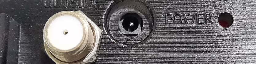
What bands and wireless providers are served with this booster? Frequency Bands: LTE-707(Band12, 17)/LTE-781(Band13)/Cellular850 (Band5)/PCS-1900(Band2, 25)/AWS2100 (Band4). This equipment is a multiband signal amplifier which supports: Cellular 850 MHz, PCS 1900 MHz, AWS and 700 MHz for both AT&T and Verizon-4G networks as well as the Sprint 4G G-Block of 1900 MHz. SolidRF SR25652001 Delivers up to 70 dB of gain and supports CDMA, GSM, EVDO, LTE, HSPA+ and WCDMA technologies. How does it work? 1. The outside antenna receives week signal from base station and sends it to the booster through outside cable. The booster can filter and amplify the signal. Then the inside antenna broadcasts the improved signal to indoor space to enhance the cellphone signal. 2. When user’s mobile terminal transmits, the booster amplifies the cellphone’s signal from the inside antenna and sends it to outside antenna through cables. The amplified signal will be transmitted to the wireless provider’s tower. The whole process of the communication link is established. Why use a Booster? Someone using mobile devices cannot connect to the base station signal; experiences call failure, or are unable to connect to the internet. Which this occurs, it is generally due to one of two reasons: 1. Location of the nearest cell tower – cell towers are situated to provide broad coverage; however, there are many areas in which signal strength may be reduced by topographic features or by local government restrictions on the height or placement of the towers themselves. Rural areas generally have fewer cell towers than urban regions. 2. Natural and man-made obstructions – signal strength can also be negatively affected by trees, hills, buildings, weather, and other obstructions. You may be relatively close to a cell tower but still unable to make a call. This often occurs in homes and other buildings in which stucco, concrete or metal walls may block the signal. Easily solve these problems by installing a SolidRF booster. Overview of installation 1. Select installation location away from direct sunlight, heat, water and proper ventilation. Do NOT install in a sealed enclosure. 2. Select a location on the roof of the building to install the Outside Antenna. Use a cell phone in test mode to find the strongest signal from the cell tower. Visit www.solidrftech.com to find test mode function for your particular cell phone. 3. Run the Outside Antenna cable to the Signal Booster and attach it to the connector labeled “Outside Antenna” on the Signal Booster. Run the Inside Antenna cable first to the splitter then to the Signal Booster and attach it to the connector labeled “Inside Antenna” on the Signal Booster. Lightning Surge Protection is recommended for all in-building installations. 4. Before powering up the Signal Booster, verify that both the Outside Antenna and the Inside Antenna are connected and check that all connections are tight. Note: Be careful when plugging the connectors in so as not to bend the center pins on the connectors. 5. The Signal Booster has been packaged with the gain control knobs adjusted to the highest gain position. If any of the lights are not green, please refer to page 6 – Band Lights. Warning: Connecting the Signal Booster directly to a cell phone with use of an adapter will damage the cell phone and/or the Signal Booster. Booster function Figure 1 OUTSIDE:Outside port is connected to outdoor cable, outdoor antenna, lighting arrester. INSIDE: Port to the indoor cable, indoor antennas, coupler, power splitters. LED display: it shows the signal strength (see table 1) of selected band. LED show Output power 0 ≤-80dBm 1 ≥-70dBm 2 ≥-60dBm 3 ≥-50dBm 4 ≥-40dBm 5 ≥-30dBm 6 ≥-15dBm 7/8 ≥0dBm E Over heat / the antennas are NOT installed properly. F Self-Protection Table 1 MODE button: press it to choose LED display modes: 1. Turn off all display (except power light). 2. Display circularly the output signal strength of 700MHz, 800Mhz, 1900Mhz and 1700/2100MHz. 3. Display the output signal strength of the band selected by PRESS Band button. Band button: when LED display mode has been set as MODE 3, press it to choose a band and display its output signal strength on LED. Blue knobs: adjust the booster’s gain from minimum 40dB to maximum 70dB. Band lights: it shows the status of indicated band. Flicker means the booster fail on the band. Power light: It indicated whether the power is turn on. Find the strongest signal position When installing your Signal Booster’s Outside Antenna, aiming it towards the best signal source from your service provider is important. The best way of getting the strongest signal is to have one person on the roof to rotate the Outside Antenna, which is connected to the Signal Booster. Turning the Outside Antenna about 45 degrees at a time, while the second person is watching the signal strength on the phone inside the building. This allows you to read the signal strength from the cell tower. It is preferable to have the phone in the test mode: The IPhones: Dial *3001#12345#*, The top left corner can be displayed as - 80dBm (strong or weak signal values will change). The android mobile phones: Dial *#*#4636#*#*,Click the phone information. Signal strength: - 80dBm (strong or weak signal values will change). You can download several apps to measure exact signal strength. Look up “check real signal strength” to find a cell signal measurement app mode so the actual signal strength can be read, as bars are not the most accurate. Go to www.solidrftech.com for help in finding the test mode for your phone. Allow at least 30 seconds for the phone to register signal strength. Figure 2 Signal readings usually appear as a negative number (for example, -68dBm). The closer you get to zero the stronger the signal (see figure 2) Install the outdoor antenna and cable technique If you are mounting the Outside Antenna on the roof of your building, we have found that it is easiest to run your cable underneath …
Text truncated - open the document above for the full version.
Cover Letter(s)
FCC Authorization 12/5/2014 Federal Communications Commission 7435 Oakland Mills Road Columbia, MD 21046 To Whom It May Concern: We hereby delegate CKC Certification Services, LLC (CKC CS) power of attorney to act on our behalf in matters pertaining to certification of products. The actions of CKC CS shall be considered the same as our own. Sincerely, YuChi CEO
Cover Letter(s)
12/5/2014 Federal Communications Commission 7435 Oakland Mills Road Columbia, MD 21046 Subject: Request for Temporary Confidentiality To whom it may concern: In accordance with 47CFR Section 0.457 and Section 0.459, FCC Public Notice DA04-1705 and KDB Publication 726920 pertaining to confidential material, we hereby request to hold temporarily confidential all information contained within the below identified exhibits/document categories submitted pursuant to radio equipment certification requirements for FCC ID: A7V-SR25652001 for 180 days (maximum 180 days).. 1. External Photos 2. Internal Photos 3. Test Setup Photos 4. Users Manual The above material contains trade secrets and proprietary information as specified by 47CFR 0.457(d) and technical data, which would customarily be guarded from competitors. Pre- marketing public disclosure of this information might be harmful to our company and provide unjustified benefits to our competitors. Sincerely, YuChi CEO Solidrf Communication Co.,Ltd
Cover Letter(s)
1、 、、 、Explain the MSCL Figure 1 MSCL= Path loss + Inside Cable Loss - Mobile Antenna Gain - Inside Antenna Gain a) Free space propagation loss calculation formula Path loss (dB) =32.45+20Lgf+20Lgd or Path loss (dB) =20Lgf+20LgD-27.5 f (MHz), d (km) , D(m) b) Minimum Separation Distances for MSCL base on FCC new rule Minimum Separation Distances for MSCL Calculation or Measurements D(m) Inside server antenna types Minimum separation distances D (m) Ceiling mounted (e.g., dome-type) antennas 2 Wall mounted (i.e., panel or other type) antennas 1.0 or 2* Table top antennas 1.0 * Note: Wall Mounted (i.e., Panel or other type) Antennas: Alternatively, if a manufacturer clearly specifies a minimum separation distance to consumer devices in the installation manual or other user. Documentation provided with the booster, a reasonable minimum separation distance could be up to 6feet (or 2 meters) horizontally removed from the antenna. In this case, the user would be required to ensure this minimum separation distance for all SolidRF devices authorized for use with this booster. Booster Mobile phone inside antenna Path loss spatial distance=D Inside Cable Loss MSCL 2、 、、 、MSCL Calculations Mobile Antenna Gain=0dBi Frequency D(m) Antenna Gain (dBi) inside Cable Loss(dB) Constant(dB) Path loss(dB) MSCL UL1710-1755 2 10 1.8 27.5 43.2 35 UL1850-1915 2 10 1.8 27.5 43.8 35.6 UL824-894 2 7 1.35 27.5 36.8 31.15 UL 698-716 2 7 1.3 27.5 35.3 29.6 UL776-787 2 7 1.3 27.5 36.3 30.6 3、 、、 、Equivalent isotropic radiated power (EIRP) Frequency Output Power (dBm) Outside Antenna Gain (dBi) Outside Cable Loss (dB) EIRP(dB m) Limit MAx(dBm) UL1710-1755 16.3 9.5 2.55(30feet) 23.25 30 UL1850-1915 19.4 9.5 2.9(30feet) 26 30 UL824-894 17.7 8 1.95(30feet) 23.75 30 UL 698-716 17.5 7 1.9(30feet) 22.6 30 UL776-787 19.3 7 1.9(30feet) 24.4 30 Frequency Output Power (dBm) Inside Antenna Gain (dBi) Inside Cable Loss (dB) EIRP(dB m) Limit MAx(dBm) DL2110-2155 -1.5 10 1.9 (20feet) 6.6 17 DL1930-1995 -5.4 10 1.8 (20feet) 3.7 17 DL869-894 -0.6 7 1.35 (20feet) 5.05 17 DL:728-746 -3.9 7 1.3 (20feet) 1.8 17 DL 746-757 -2.6 7 1.3 (20feet) 3.1 17 Calculation:EIRP =Output Power -Cable loss + Antenna gain
Cover Letter(s)
12/5/2014 Federal Communications Commission 7435 Oakland Mills Road Columbia, MD 21046 Subject: Consumer Booster Attestation Dear Sir/Madam: We hereby request certification under part 20.21 rules for a Consumer Booster. We hereby acknowledge and agree to comply with Consumer Booster requirements for this equipment as listed in 47 CFR part 20 and KDB 935210. Furthermore we hereby attest that a) All marketing materials for this product will be restricted to individual consumer use only; we will avoid any references to “office,” “commercial,” “industrial” or any similar marketing statements; b) Network Protection Standard (NPS) and other compliance/safeguard feature have been implemented; c) NPS and other compliance/safeguard features are defaulted to “ON” configuration (in operation); d) NPS and other compliance/safeguard features cannot be field reconfigured, disabled or removed; e) Consumer booster is not user programmable, does not need fine tuning or adjustment, does not require professional installation; f) Future software upgrade will not cause non-compliance; and g) There is no access for third party configuration of frequency, power or any other regulatory parameters. Sincerely, YuChi CEO Solidrf Communication Co.,Ltd
RF Exposure Info
Page 1 of 8 Report No: 95763-17 RADIO FREQUENCY EXPOSURE REPORT FOR THE Device: Signal Booster Model: SR25652001 Report No.: 95763-17 Date of issue: October 28, 2014 PREPARED FOR: SolidRF Communication Co., Ltd E3 Building, Fenghuang Third Industry Baoan District, Shenzhen, Guangdong China PREPARED BY: Eddie Wong CKC Laboratories, Inc. 5046 Sierra Pines Drive Mariposa, CA 95338 The test data contained in this report documents the observed testing parameters pertaining to and are relevant for only the sample equipment tested in the agreed upon operational mode(s) and configuration(s) as identified herein. Compliance assessment remains the client’s responsibility. This report may not be used to claim product endorsement by A2LA or any government agencies. This test report has been authorized for release under quality control from CKC Laboratories, Inc. Steve Behm Director of Quality Assurance & Engineering Services CKC Laboratories, Inc. Page 2 of 8 Report No: 95763-17 Purpose: To demonstrate compliance with United States, Canada and/or European Union RF Exposure requirements for Portable equipment (devices used ≤20cm from the body) or Mobile equipment (devices used >20cm from the body) with power output below exemption levels and Mobile equipment, where Maximum Permissible Exposure (MPE) Calculations apply. United States Compliance Requirements (1.1310): RF Exposure Evaluation Limits Occupational / Controlled Exposure Frequency Range (MHz) Electric Field Strength (V/m) Magnetic Field Strength (A/m) Power Density (mW/cm 2 ) Averaging Time (minutes) 0.3-3.0 614 1.63 *(100) 6 3.0-30 1842/f 4.89/f *(900/f 2 ) 6 30-300 61.4 0.163 1 6 300-1500 --- --- f/300 6 1500-100,000 --- --- 5.0 6 RF Exposure Evaluation Limits General Population / Uncontrolled Exposure Frequency Range (MHz) Electric Field Strength (V/m) Magnetic Field Strength (A/m) Power Density (mW/cm 2 ) Averaging Time (minutes) 0.3-1.34 614 1.63 *(100) 30 1.34-30 824/f 2.19/f *(180/f 2 ) 30 30-300 27.5 0.073 0.2 30 300-1500 --- --- f/1500 30 1500-100,000 --- --- 1.0 30 * Plane wave equivalent power density Limit is calculated based on the mid-band frequency used in the operating frequency range. Exemption Level: Power output <60/f GHz (mW) Page 3 of 8 Report No: 95763-17 Canadian Compliance Requirements (RSS-102): RF Exposure Evaluation Limits Occupational / Controlled Exposure Frequency Range (MHz) Electric Field Strength (V/m) Magnetic Field Strength (A/m) Power Density (W/m 2 ) Averaging Time (minutes) 0.003-1.0 600 4.9 --- 6 1.0-10 600/f 4.9/f --- 6 10-30 60 4.9/f --- 6 30-300 60 0.163 10 6 300-1500 3.54 f 0.5 0.0094*f 0.5 f/3 6 1500-15,000 137 0.364 50 6 15,000-150,000 137 0.364 50 616000/f 1.2 RF Exposure Evaluation Limits General Population / Uncontrolled Exposure Frequency Range (MHz) Electric Field Strength (V/m) Magnetic Field Strength (A/m) Power Density (W/m 2 ) Averaging Time (minutes) 0.003-1.0 280 2.19 --- 6 1.0-10 280/f 2.19/f --- 6 10-30 28 2.19/f --- 6 30-300 28 0.073 2 6 300-1500 1.585 * f 0.5 0.0042 * f 0.5 f/150 6 1500-15,000 61.4 0.163 10 6 15,000-150,000 61.4 0.163 10 616000/f 1.2 *Power density limit applicable >100MHz Exemption Level: Frequency Range (MHz) Maximum Output Power (Conducted or EIRP) 0.003-1000 ≤ 200 mW 1000-2200 ≤ 100 mW 2200-3000 ≤ 20 mW 3000-6000 ≤ 10 mW Page 4 of 8 Report No: 95763-17 European Union Compliance Requirements (ICNIRP): RF Exposure Evaluation Limits Occupational / Controlled Exposure Frequency Range (MHz) Electric Field Strength (V/m) Magnetic Field Strength (A/m) Power Density (W/m 2 ) Averaging Time (minutes) 0.00082-0.065 610 24.4 --- 6 0.065-1.0 610 1.6/f --- 1.0-10 610/f 1.6/f --- 6 10-400 61 0.16 10 6 400-2000 3.0 * f 0.5 0.008 * f 0.5 f/40 6 2000-300,000 137 0.36 50 6 RF Exposure Evaluation Limits General Population / Uncontrolled Exposure Frequency Range (MHz) Electric Field Strength (V/m) Magnetic Field Strength (A/m) Power Density (W/m 2 ) Averaging Time (minutes) 0.003-0.150 87 5.0 --- 6 0.150-1.0 87 0.73/f -- 6 1.0-10 87/f 0.5 0.73/f --- 6 10-400 28 0.073 2 6 400-2000 1.375 f 0.5 0.0037*f 0.5 f/200 6 2000-300,000 61 0.16 10 6 *Power density limit applicable >100MHz Exemption Level: Power output < 20mW 1 1 May vary by product type Page 5 of 8 Report No: 95763-17 Device and Antenna Operating Configuration: Device operating at maximum output power with continuous transmission of modulated data. The MPE calculation is based on highest output power, worse case being the Uplink path. Ant Gain Cable Loss 9.5 2.55 9.5 2.9 8 1.95 7 1.9 7 1.96 Test Procedure: This equipment is evaluated in accordance with the guidelines set forth in OET Guide 65 & ANSI C95.1 for the US and Health Canada Safety Code 6 & RSS 102 for Canada. Other Considerations: None Page 6 of 8 Report No: 95763-17 MPE Calculations Applicability: Limit Used X General Population / Uncontrolled Exposure Occupational / Controlled Exposure RF Exposure Exemption No United States NA Canada NA Europe Equipment operational details: Config# Freq Range Meas Power (dBm) Antenna Gain (dBi)+Cable Loss Antenna Type EIRP (dBm) EIRP (mW) US mW/cm 2 1 UL1710-1755 16.3 6.95 External 2.33E+01 211.348904 1.00 2 UL1850-1915 19.4 6.60 External 2.60E+01 398.1071706 1.00 3 UL824-894 17.7 6.05 External 2.38E+01 237.1373706 0.60 4 UL 698-716 17.5 5.10 External 2.26E+01 181.9700859 0.48 5 UL 776-787 19.3 5.04 External 2.44E+01 272.8977783 0.52 Measurements based from EMC Test Report(s): 95763-13 MPE Calculation: 2 4d EIRP DensityPower Given: EIRP in mW or W and d in cm or m Config Freq Range EIRP Distance US # (mW) (cm) mW/cm 2 Limit 1 UL1710- 1755 211.348904 20.00 0.04 1.00 2 UL1850- 1915 398.107171 20.00 0.08 1.00 3 UL824-894 237.137371 20.00 0.05 0.60 4 UL 698-716 181.970086 20.00 0.04 0.48 5 UL 776-787 272.897778 20.00 0.05 0.52 Page 7 of 8 Report No: 95763-17 Summary Exemptions: In the case the equipment meets compliance requirements by exemption the product is approved for use under mobile or portable conditions without further tes…
Text truncated - open the document above for the full version.
Test Report
This report contains a total of 182 pages and may be reproduced in full only. Partial reproduction may only be done with the written consent of CKC Laboratories, Inc. SolidRF Communication Co., Ltd ADDENDUM TO TEST REPORT 95763-13 Signal Booster Model: SR25652001 Tested To The Following Standards: FCC Part 20.21 Report No.: 95763-13A Date of issue: December 8, 2014 This test report bears the accreditation symbol indicating that the testing performed herein meets the test and reporting requirements of ISO/IEC 17025 under the applicable scope of EMC testing for CKC Laboratories, Inc. We strive to create long-term, trust based relationships by providing sound, adaptive, customer first testing services. We embrace each of our customers’ unique EMC challenges, not as an interruption to set processes, but rather as the reason we are in business. Page 2 of 182 Report No.: 95763-13A TABLE OF CONTENTS Administrative Information ........................................................................................................................................... 4 Test Report Information ............................................................................................................................................ 4 Revision History ......................................................................................................................................................... 4 Report Authorization ................................................................................................................................................. 4 Test Facility Information ............................................................................................................................................ 5 Software Versions ...................................................................................................................................................... 5 Site Registration & Accreditation Information .......................................................................................................... 5 Summary of Results ................................................................................................................................................... 6 Conditions During Testing.......................................................................................................................................... 6 Equipment Under Test ............................................................................................................................................... 7 Peripheral Devices ..................................................................................................................................................... 7 FCC Part 20.21 ............................................................................................................................................................... 8 Clause 7.1 Authorized Frequency Band Verification ................................................................................................. 8 Summary of Results ............................................................................................................................................... 9 Clause 7.2 Maximum Power .................................................................................................................................... 18 Summary of Results ............................................................................................................................................. 19 Clause 7.3 Maximum Gain ....................................................................................................................................... 22 Summary of Results ............................................................................................................................................. 23 Clause 7.4 Intermodulation Product ........................................................................................................................ 24 Summary of Results ............................................................................................................................................. 25 Clause 7.5 Out of Band Emissions ............................................................................................................................ 36 Summary of Results ............................................................................................................................................. 37 Clause 7.7 Noise limit ............................................................................................................................................ 130 Summary of Results ........................................................................................................................................... 131 Clause 7.8 Uplink Inactivity .................................................................................................................................... 147 Summary of Results ........................................................................................................................................... 148 Clause 7.9 Booster Gain Limit ................................................................................................................................ 151 Summary of Results ........................................................................................................................................... 153 Clause 7.11 Oscillation Detection .......................................................................................................................... 159 Summary of Results ........................................................................................................................................... 160 Page 3 of 182 Report No.: 95763-13A Exhibit A: Test Setup Photos .................................................................................…
Text truncated - open the document above for the full version.
Test Report
Page 96 of 182 Report No.: 95763-13A UL_1710-1755MHz_GSM_L PreAGC UL_1710-1755MHz_GSM_H PreAGC Page 97 of 182 Report No.: 95763-13A UL_1850-1915MHz_GSM_L_0dBm UL_1850-1915MHz_GSM_H_0dBm Page 98 of 182 Report No.: 95763-13A UL_1850-1915MHz_GSM_L -37dBm UL_1850-1915MHz_GSM_H -31dBm Page 99 of 182 Report No.: 95763-13A UL_1850-1915MHz_GSM_L PreACP UL_1850-1915MHz_GSM_H PreAGC Page 100 of 182 Report No.: 95763-13A DL_728-746MHz_LTE_L -20dBm_2 DL_728-746MHz_LTE_H -20dBm Page 101 of 182 Report No.: 95763-13A DL_728-746MHz_LTE_ L_-48dBm DL_728-746MHz_LTE_ H_-47dBm Page 102 of 182 Report No.: 95763-13A DL_728-746MHz_LTE_ L_pre AGC DL_728-746MHz_LTE_ H_pre AGC Page 103 of 182 Report No.: 95763-13A DL_746-757MHz_LTE_L -20dBm DL_746-757MHz_LTE_H-20dBm Page 104 of 182 Report No.: 95763-13A DL_746-757MHz_LTE_ L_-47dBm DL_746-757MHz_LTE_ H_46dBm Page 105 of 182 Report No.: 95763-13A DL_746-757MHz_LTE_ L_pre AGC DL_746-757MHz_LTE_ H_pre AGC Page 106 of 182 Report No.: 95763-13A DL_869-894MHz_LTE_L -20dBm2 DL_869-894MHz_LTE_H -20dBm2 Page 107 of 182 Report No.: 95763-13A DL_869-894MHz_LTE_ L_-47dBm DL_869-894MHz_LTE_ H_-48dBm Page 108 of 182 Report No.: 95763-13A DL_869-894MHz_LTE_ L_pre AGC2 DL_869-894MHz_LTE_ H_pre AGC Page 109 of 182 Report No.: 95763-13A DL_1930-1995MHz_LTE_L -20dBm DL_1930-1995MHz_LTE_H -20dBm Page 110 of 182 Report No.: 95763-13A DL_1930-1995MHz_LTE_L_ -54dBm DL_1930-1995MHz_LTE_H_ -53dBm Page 111 of 182 Report No.: 95763-13A DL_1930-1995MHz_LTE_L_ pre AGC DL_1930-1995MHz_LTE_H_ pre AGC Page 112 of 182 Report No.: 95763-13A DL_2110-2155MHz_LTE_L -20dBm DL_2110-2155MHz_LTE_H_-20dBm Page 113 of 182 Report No.: 95763-13A DL_2110-2155MHz_LTE_L_ -56dBm DL_2110-2155MHz_LTE_H_-53dBm Page 114 of 182 Report No.: 95763-13A DL_2110-2155MHz_LTE_L_ pre AGC DL_2110-2155MHz_LTE_ H_pre AGC Page 115 of 182 Report No.: 95763-13A UL_698-716MHz_LTE_L_0dBm UL_698-716MHz_LTE_H_0dBm Page 116 of 182 Report No.: 95763-13A UL_698-716MHz_LTE_L AGC -31 UL_698-716MHz_LTE_H AGC -325 Page 117 of 182 Report No.: 95763-13A UL_698-716MHz_LTE_L PreAGC UL_698-716MHz_LTE_H PreAGC Page 118 of 182 Report No.: 95763-13A UL_776-787MHz_LTE_L_0dBm UL_776-787MHz_LTE_H_0dBm Page 119 of 182 Report No.: 95763-13A UL_776-787MHz_LTE_L AGC -29 UL_776-787MHz_LTE_H AGC -29 Page 120 of 182 Report No.: 95763-13A UL_776-787MHz_LTE_L PreAGC UL_776-787MHz_LTE_H PreAGC Page 121 of 182 Report No.: 95763-13A UL_824-849MHz_LTE_L_0dBm UL_824-849MHz_LTE_H_0dBm Page 122 of 182 Report No.: 95763-13A UL_824-849MHz_LTE_L AGC-28 UL_824-849MHz_LTE_H PreAGC -26 Page 123 of 182 Report No.: 95763-13A UL_824-849MHz_LTE_L PreAGC UL_824-849MHz_LTE_H PreAGC Page 124 of 182 Report No.: 95763-13A UL_1710-1755MHz_LTE_L_0dBm UL_1710-1755MHz_LTE_H_0dBm Page 125 of 182 Report No.: 95763-13A UL_1710-1755MHz_LTE_L PreAGC UL_1710-1755MHz_LTE_H PreAGC Page 126 of 182 Report No.: 95763-13A UL_1710-1755MHz_LTE_L ACP -39dBm UL_1710-1755MHz_LTE_H -39dBm Page 127 of 182 Report No.: 95763-13A UL_1850-1915MHz_LTE_L_0dBm UL_1850-1915MHz_LTE_H_0dBm Page 128 of 182 Report No.: 95763-13A UL_1850-1915MHz_LTE_L -38dBm UL_1850-1915MHz_LTE_H ACP -304 Page 129 of 182 Report No.: 95763-13A UL_1850-1915MHz_LTE_L PreAGC UL_1850-1915MHz_LTE_H PreAGC Page 130 of 182 Report No.: 95763-13A Clause 7.7 Noise limit Test Conditions / Setup Test Location: CKC Laboratories, Inc. • 110 N. Olinda Place • Brea, CA 92821 • 714-993-6112 Customer: SolidRF Communication Co., Ltd Specification: 7.7 Noise Limit procedure Variable Noise Variable Noise Timing Work Order #: 95763 Date: 9/16/2014 Test Type: Conducted Emissions Time: 08:40:44 Equipment: Signal Booster Sequence#: 1 Manufacturer: SolidRF Communication Co., Ltd Tested By: E. Wong Model: SR25652001 110V 60Hz S/N: NA Test Equipment: ID Asset # Description Model Calibration Date Cal Due Date AN02672 Spectrum Analyzer E4446A 8/14/2013 8/14/2015 AN03430 Attenuator 75A-10-12 9/5/2013 9/5/2015 AN02946 Cable 32022-2-2909K- 36TC 7/31/2013 7/31/2015 Equipment Under Test (* = EUT): Function Manufacturer Model # S/N Signal Booster* SolidRF Communication Co., Ltd SR25652001 NA Support Devices: Function Manufacturer Model # S/N Power Supply Generic MX18W1 NA Signal Generator Agilent E4438C MY42081492 Signal Generator Agilent E4433B US40052164 Test Conditions / Notes: The EUT is placed on the test bench. Evaluation performed at the Outside ( Donor) and Inside ( Server) antenna port. UL: 824-849, 1850-1915 MHz, 1710-1755MHz, 698-716MHz, 776-787MHz DL: 869-894, 1930-1995 MHz, 2110-2155MHz, 728-746MHz, 746-757MHz All adjustable settings on the test sample are set at max. Test environment conditions: Temperature: 23.9°C, Relative Humidity: 40%, Atmospheric Pressure: 100kPa Test procedure: The test was performed IAW section 7.7 of the FCC document: 935210 D03 Wideband Consumer Signal Booster Measurement Guidance v02r01 Dated July 24, 2014 Firmware: 092914 version Modification: 10/6/14 By pass two stage of amplifier in UL/DL path to comply with Transmit Off mode requirement. Page 131 of 182 Report No.: 95763-13A Summary of Results Maximum Noise Power Freq Measured Limit Margin MHz dBm./MHz dBm/MHz UL1710-1755 -38.8 -37.7 -1.1 UL1850-1915 -40.5 -37.0 -3.5 UL824-894 -44.8 -44.1 -0.7 UL 698-716 -46.0 -45.5 -0.5 UL776-787 -46.0 -44.6 -1.4 DL2110-2155 -41.6 -37.7 -3.9 DL1930-1995 -41.0 -37.0 -4.0 DL869-894 -46.0 -44.1 -1.9 DL:728-746 -47.5 -45.5 -2.0 DL 746-757 -49.4 -44.6 -4.8 -90.0 -80.0 -70.0 -60.0 -50.0 -40.0 -30.0 -90.0-80.0-70.0-60.0-50.0-40.0-30.0-20.0 Transmit Noise dBm/MHz RSSI dBm 7.7 Booster UL Noise Limit 1710-1755 UL Limit 1850-1915MHz UL Limit Data _UL 1710-1755MHz Data_UL 1850-1915MHz TX power off limit Page 132 of 182 Report No.: 95763-13A 1710.0 1755.0 MHz Limit Margin RSSI Measured RSSI Freq TX off (dBm) Noise (dBm/MHz) Dependent Dependent -75.0 -38.0 -37.7 -0.3 -73.0 -38.1 -37.7 -0.4 -90.0 -38.3 -37.7 -0.6 -80.0 -38.6 -37.7 -0.9 -53.0 -50.3 -50.0 -0.3 -54.0 -50.8 -49.0 -1.8 -20.0 -81.2 -70 -11.2 1850.0 1915.0 MHz Limit Margin RSSI Measured RSSI Freq …
Text truncated - open the document above for the full version.
Test Report
This report contains a total of 26 pages and may be reproduced in full only. Partial reproduction may only be done with the written consent of CKC Laboratories, Inc. SolidRF Communication Co., Ltd TEST REPORT FOR Signal Booster…
Text truncated - open the document above for the full version.
Contact Information
Applicant
Yu Chi(CEO)
Test Firm
CKC Laboratories, Inc.Steve Behm
Technical Specifications
| # | Rule Parts | Frequency Range | Power Output | Emission | Tolerance |
|---|---|---|---|---|---|
| 4 | 27 | 2.11 GHz - 2.15 GHz | 710.00 µW | D7W | Amp |
Other Applications from ShenZhen SolidRF Communications Co., Ltd
A7V-SR15652001
Jul 30, 2021Signal Booster
Equipment Class
B2W - Part 20 Wideband Consumer Booster (CMRS)
A7V-SR55652001
Jul 20, 2021Signal Booster
Equipment Class
B2W - Part 20 Wideband Consumer Booster (CMRS)
A7V-SR87503001
Jan 05, 2020Signal Booster
Equipment Class
B2W - Part 20 Wideband Consumer Booster (CMRS)
A7V-SR25502001
Mar 02, 2015Mobile Consumer Booster
Equipment Class
B2W - Part 20 Wideband Consumer Booster (CMRS)
A7V20102201
Mar 01, 2012Dual Band Wireless Cell Phone Signal Amplifier
Equipment Class
PCB - PCS Licensed Transmitter