AB6MOBKITInductive Charging unit for a Cordless Telephone
Avaya Canada Corporation
Click to zoom
Application Details
- Equipment Class
- 8CC - Part 18 Consumer Device
- Date of Grant
- Aug 25, 1998
- Application Purpose
- Original Equipment
- Date of Application
- Aug 03, 1998
- Equipment Note
- Inductive Charging unit for a Cordless Telephone
- Frequency Range
- 0.07000000 - 0.07200000
- Company
- Avaya Canada Corporation
- Country
- Canada
Documents & Files
Document Text
Text extracted from the exhibit documents filed with the FCC. Open a document above to read the original.
Users Manual
Owner’s Manual 1 WELCOME TO THE WORLD OF MOBILITY! Your new Mobility Kit gives you the freedom to move about a room without the inconvenience of becoming tangled in a cord. All the great features of your PowerTouch/Vista base telephone are still available. You must continue to return your uncorded handset to the base cradle when a call ends and you must use the Flash/Link key on the base to answer a Call Waiting call. All other features of your PowerTouch/Vista phone, such as the large display, Callers List, Directory and Redial List continue to be accessed from your base telephone. If the Mobility KitMobility Kit is already installed, read the sections Tips for using the Mobility Handset , Connecting the Battery Pack and Mobility Handset Usage . If your Mobility Kit did not come already installed on your PowerTouch/Vista telephone, see the following pages for complete instructions on installing your new Mobility Kit. P0882980.01.EFS.UG Page 1 Monday, July 27, 1998 11:24 AM Owner’s Manual 2 Tips for using the Mobility Handset... n Place the Handset into the base cradle, for approx- imately 10 hours, to charge before first use. n You may move up to 10 meters/30 feet from your base telephone when using the Mobility Handset.* n You MUST dial numbers using the base keypad. n You MUST return the Handset to the base cradle to end calls and charge the battery. n Press the Scan key on the side of the Handset if you hear any static—this will locate the next clearest channel. n Use the Flash/Link key on the base to answer Call Waiting calls. n A solid red light on the Mobility Device indicates that the Handset is in the base and charging. A flashing light indicates that the Handset and base are not communicating—place the Handset in the base cradle until the light turns solid and try your call again. n The power adapter supplied with the Mobility Kit MUST be used (model 48115OT). n Use the base volume control to adjust the Mobility Handset’s volume. n If you hear a rapid repetition of beeps, return the Mobility Handset to the base cradle. n All other keys and lists on the base function as usual. n Once installed, do not remove the Mobility Device. * Various environmental circumstances may increase or lessen the distance. See Mobility Handset usage... on page 3 for more information. P0882980.01.EFS.UG Page 2 Monday, July 27, 1998 11:24 AM Owner’s Manual 3 Mobility Handset usage... When using the Mobility Handset you must always return the Handset to the base cradle. If you fail to do so, you will not disconnect your calls (your telephone line will remain engaged and callers will hear a busy tone). You also need to return the Mobility Handset to the base cradle to charge. Each time you remove the Handset from the base cradle, the available talk time is slowly reduced—when the Handset is placed back in the base, charging resumes. When the Mobility Handset’s battery pack is close to empty, you will hear two beeps (every 30 seconds). To fully recharge the Handset’s battery pack, place the Mobility Handset into the base cradle for at least 10 hours. When you have fully charged the Mobility Hand- set’s battery pack, you will be able to speak (talk time) for up to 8 hours without recharging. Although the Mobility Handset has an approximate range of up to10 meters/30 feet, proximity to fluores- cent lights, stereo equipment, and household appli- ances may affect the range. P0882980.01.EFS.UG Page 3 Monday, July 27, 1998 11:24 AM Owner’s Manual 4 Connecting the Battery Pack... ¶ Connect the battery pack to the Mobility Handset and replace the cover. · Place the Handset into the base for at least 10 hours to charge. Replacing the Handset battery pack... The battery pack supplied with your Mobility Kit will eventually need replacing. When this occurs, replace the battery pack with a Ni-cd, 3.6V, 300 mAh, model GP30AAK3BMJ. P0882980.01.EFS.UG Page 4 Monday, July 27, 1998 11:24 AM Owner’s Manual 5 The Mobility Kit... Mobility Device Power Control Unit Handset jack and cord 5-pin Power Connector Battery Pack Battery pack Battery pack Scan key connector Power Adapter Replace with Ni-cd, 3.6V, 300 mAh compartment cover model GP30AAK3BMJ Model 481151OT (Winbond) Long Screw (3.5 mm X 20 mm/.14 in X .79 in) P0882980.01.EFS.UG Page 5 Monday, July 27, 1998 11:24 AM Owner’s Manual 6 Installing the Mobility Kit... ¶ Disconnect the corded handset currently attached to your base. · Remove the short screw in the back of the base. ̧ Place the Mobility Device over the back of the base and, using the long screw provided, attach the Mobility Device to the base—DO NOT overtighten. ¶ · ̧ P0882980.01.EFS.UG Page 6 Monday, July 27, 1998 11:24 AM Owner’s Manual 7 ¹ Route the power adapter cord through the hole in the stand before inserting the Power Connector into the Power Control Unit marked . º Insert the Handset Jack (hanging from the Mobility Device), into the jack formerly used by the corded handset and marked . » Route the Power Control Unit’s cord along the channel in the base. Note: Do not use the stand when wall mounting. ¹ º » P0882980.01.EFS.UG Page 7 Monday, July 27, 1998 11:24 AM Owner’s Manual 8 ¼ Insert the Power Control Unit into the base by pressing into the hole marked . ½ Insert one end of the telephone line cord into the jack marked on the back of the base.* ¾ Insert the other end of the telephone line cord into a wall outlet and the power adapter to an electrical out- let.* * For further information on line cord installation, you can refer to your telephone’s User Guide. ½ ¼ ¾ ¾ P0882980.01.EFS.UG Page 8 Monday, July 27, 1998 11:24 AM Owner’s Manual 9 ¿ Attach the stand in the high viewing angle position or in the low viewing angle position . Route the line cord and power cords through the channels on the stand—the phone will then sit flat. Note: Do not use the stand when wall mounting. ¿ P0882980.01.EFS.UG Page 9 Monday, July 27, 1998 11:24 AM Guide d’utilisation 10 BIENVENUE DANS LE MONDE DE LA MOBILITÉ! Grâc…
Text truncated - open the document above for the full version.
Cover Letter(s)
Northe rn Te le com 2305 Mission College Blvd. Santa Clara. CA 95054-1591 August 4, 1998 Fe de ral Communications Commission Equipment Authorization Branch 7435 Oakland Mills Rd. Columbia, MD 21046 Reference: FCC ID: AB6MOBKIT Dear Sir / Madam: Enclosed is Northern Telecom, Inc.'s application for CERTIFICATION of an Inductive Charging unit, subject to Part 18, ISM Equipment. This inductive charging unit is incorporated into the Nortel Mobility Kit, to be used with certain telephones specified in the Certification Applications for Part 15 under FCC ID Numbers: AB6MOBKITB (Base unit) and AB6MOBKITH (Handset unit). The installation and users manual and labeling information is contained in both of these Part 15 applications. The label is being changed to reflect a second FCC ID: AB6MOBKIT the base and handset label. This is part of a battery charging circuit for the Nortel Mobility Kit. The Nortel Mobility Kit is manufactured for Nortel by: S. Megga 1 Kw ai Hei St. Kw ai Chung N.T. Hong Kong, China If you have any questions, please feel free to call me at (408) 565-2046, or e-mail at [email protected]. Sincerely, John Shinn, P.E. Corporate FCC Single Point Contact Homologation Engineering Northern Telecom, Inc.
Cover Letter(s)
Northern Telecom 2305 Mission College Blvd. Santa Clara. CA 95054-1591 August 14, 1998 Federal Communications Commission Equipment Authorization Branch 7435 Oakland Mills Rd. Columbia, MD 21046 Reference: FCC ID: AB6MOBKIT Dear Joe Dichoso Enclosed is Northern Telecom, Inc.'s Form 159 covering the additional fees of $130.00 for the request for confidentiality. A Request, pursuant to 47 CFR 0.459 of the commission's rules, that the following sections and documents be held CONFIDENTIAL due to their proprietary nature. We consider this leading edge technology developed by Nortel and our partners and being new technology, we do not wish to be disclosed or otherwise made available to our competition. Specifically, the Circuit Schematics contained in the application. If you have any questions, please feel free to call me at (408) 565-2046, or e-mail at [email protected]. Sincerely, John Shinn, P.E. Corporate FCC Single Point Contact Homologation Engineering Northern Telecom, Inc.
Operational Description
Description FCC ID: AB6MOBKITH and FCC ID: AB6MOBKITB Trade Name: Nortel Mobility Kit Product Code: NTHK02xxyy The “Nortel Mobility Kit” uses an inductive type charging circuit to replenish the handset battery. Essentially there are two inductors, one in the handset and one in the RF Module separated by air which in this case is the core (when in idle mode, on-hook the handset and RF Module rest against each other). The frequency of the charge circuitry is between 70kHz and 72kHz. The variation in frequency is caused by component tolerance within the entire charge circuit. The nominal current flow within the charge circuit is 23 mA.
Test Report
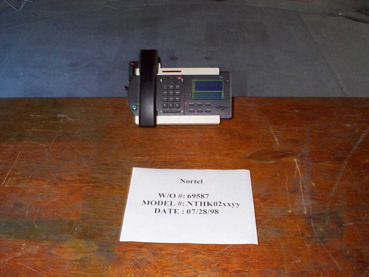
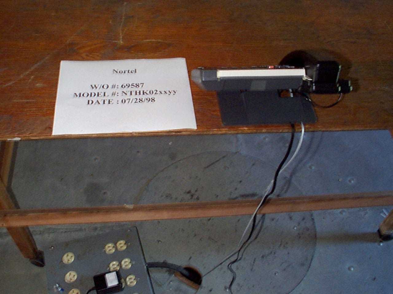
CKC LABORATORIES INC. 22105 Wilson River Hwy, Site A Tillamook, Oregon 97141 (800) 500-4EMC Customer: Nortel Work Order #: 69587 Specification: FCC 18.305 Date: Tue Jul-28-1998 Test Type: Maximized Emissi o Time: 15:16:56 Conducted By: Mike Wilkinson Sequence # 1 Equipment: Nortel Mobility Kit Manufacturer: Nortel S/N: None Model#: NTHK02xxyy FCC ID:AB6M0BKITB EMI Meters S/N Cal Date Due HP 8574A 3010A01076 11/25/98HP 8447D 2727A05392 4/28/99 HP 8596E 3346A00209 12/13/98HP 83017A 3123A00283 3/23/99 Equipment Under Test (* = EUT) Function Manufactu r Model# S/N FCC ID * Nortel Mobility Kit Nortel NTHK02xxyy None AB6M0BKITB Nortel Mobility Kit Nortel NTHK02xxyy None AB6M0BKITH Support Devices Function Manufactu r Model# S/N FCC ID Vista/Power Touc h Nortel NT2n52AB11 None N/A Remote Phone Nortel NT2N24AD2131 None N/A Test Conditions Test setup and measurements make as per ANSI63.4 1992 EUT is comprised of a base unit FCC ID# AB6M0BKITB and handset FCC ID# AB6M0BKITB. EUT is a intentional radiating cordless phone kit operating in the frequency range of 43 to 49 MHz and does not operate in any of the FCC 18.303 Prohibited Frequency Bands. The EUT handset is placed on the host phone in the on hook postion and a hands off call was established to a remote phone via a 125" RJ-11 cable connected to a active CO line. The CO line cable was routed from the host phone through the ground plane to the remote phone. Frequency range investigated was 9 KHz to 30 MHz. The temperature was 78 deg. F. and the humidity was 58%. Test equipment used was: HP model 8574A s/n 3010A01076 due cal 11-25-98 and Emco rod antenna model 3301B due cal 4-26-99 Test Distance: 10 Meters Readings listed in order taken. # Freq Rdng CorrFactors Dist Corr Spec Margin Polar Type Table Ant dBμV dBμV/m 1 54.000k 44.1 3.7 0 47.8 55 -7.2 Vert Average 2 427.400k 31.8 3.5 0 35.3 55 -19.7 Vert 3 358.600k 34.2 3.5 0 37.7 55 -17.3 Vert 4 2.194M 28.8 3.8 0 32.6 55 -22.4 Vert 5 6.964M 21.1 4.7 0 25.8 55 -29.2 Vert 6 27.648M 13.9 8.5 0 22.4 55 -32.6 Vert 7 30.746M 23.5 10.1 0 33.6 55 -21.4 Vert Notes
Contact Information
Applicant
Gwendolyn Faino(Legal Director)
Technical Contact
Northern Telecom, Inc.John M Shinn
[email protected](408) 565-2046
2305 Mission College Blvd. · Santa Clara, California · United States
Non-Technical Contact
Northern Telecom, Inc.John M Shinn
[email protected](408) 565-2046
Test Firm
CKC Laboratories, Inc.Steve Behm
Technical Specifications
| # | Rule Parts | Frequency Range | Power Output |
|---|---|---|---|
| 1 | 18 | 0.07 MHz - 0.072 MHz | - |
Other Applications from Avaya Canada Corporation

AB6NT2100V3231
Mar 30, 2008AWS Radio
Equipment Class
TNB - Licensed Non-Broadcast Station Transmitter
AB6BTS9000
Dec 19, 2007Base Transceiver Station
Equipment Class
PCB - PCS Licensed Transmitter
AB6NT2100MFRM3
Oct 10, 2007NT2100 MFR M3 AWS radio
Equipment Class
TNB - Licensed Non-Broadcast Station Transmitter
AB6NTQ220AB
Jun 12, 2007NTQ220ABE5 Radio Module
Equipment Class
TNB - Licensed Non-Broadcast Station Transmitter
AB6BTS6000D
Jun 07, 2007GSM 6000 Base Transceiver Station
Equipment Class
PCB - PCS Licensed Transmitter