AB6NT800MFRMCDMA Cellular Base Station
Avaya Canada Corporation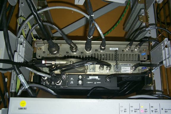
Click to zoom
Application Details
- Equipment Class
- TNB - Licensed Non-Broadcast Station Transmitter
- Date of Grant
- Mar 06, 2001
- Application Purpose
- Original Equipment
- Date of Application
- Mar 06, 2001
- Equipment Note
- CDMA Cellular Base Station
- Frequency Range
- 869.00000000 - 894.00000000
- Company
- Avaya Canada Corporation
- Country
- Canada
Documents & Files
Document Text
Text extracted from the exhibit documents filed with the FCC. Open a document above to read the original.
Users Manual
Received March 6, 2001 at AmericanTCB: Bill, This email is intended to provide clarification on the operation description provided in the AB6NT800MFRM filing. The title page for this exhibit included in the filing was incorrectly labeled 1900 MFRM. It should actually read 800 MFRM in place of the 1900 MFRM. The content of the operational description contains references to both 1900 MFRM and 800 MFRM because this is a common platform, which utilizes both radios. The 1900 version will be submitted for approval in the next couple of weeks. Please do not hesitate to contact me with any further questions or clarifications required for this filing. Regards Glen Moore Manager, UMTS Product Integrity Sanmina Design Solutions Phone # 403-769-5002 ESN # 758-5002 FAX # 403-769-4813 ESN FAX 758-4813 [email protected]
Cover Letter(s)
AmericanTCB CERTIFICATION APPLICATION Rev 1 \\Zwdcn003\wdc\departments\2y31\Systems Integrity\CDMA 2000\FCC filing 800_1W2 MFRM\Report Data\ATCB Filing\MFRM app&signature.doc 3/8/00 6. Cooperation 6.1 Applicant shall provide all cooperation required of it, its agents or third parties shall be provided using its best efforts and at no cost to ATCB. 6.2 Applicant shall provide and update Applicant's address, phone and facsimile numbers, as well as emergency contact information, for any situation which may arise after the close of normal business hours. ATCB agrees that such information will be held in confidence.
Cover Letter(s)
American Telecommunications Certification Body Inc. 6731 Whittier Ave, McLean, VA 22101 February 7, 2001 Glen, There are a number of issues on this application which will have to be addressed.: 1.) The label for this product is wrong. It indicates an AB6NT1900MFRM. Please correct 2.) The exterior photographs are not very helpful. Please provide additional detailed views showing all surfaces, and all exterior controls and ports. 3.) A line drawing or photo showing placement of label is required. The existing drawing does not clearly identify where the label will be placed. Perhaps a photograph using a “dummy “label would be appropriate. 4.) Interior views must be at minimum top and bottom of all circuit boards, plus overall “case open” views showing general construction features. 5.) The 731 form indicates three emission modes are available, however the Test Report only identifies two. Please address. 6.) The frequency table in Section 3.6 only identifies the IS-95 valid channels. Is this table of any use in a three channel implementation? 7.) FYI: Section 3.15 quotes ANSI J-STD-008. This is a PCS band specification, and not necessarily appropriate to 800MHz Cellular systems. 8.) FYI: In the past for occupied bandwidth, I have found 1M25 IS95 emissions best measured with a span of 7.2MHz, or 5 times the chip rate (1.228MHz) plus a fudge factor of 30KHz for RBW. I am certain these settings would work on wider emissions as well. 9.) Using the FCC 1% of 99% bandwidth rule of thumb, three carrier Occupied BW plots should use an RBW not less than ~37.5KHz. Please correct. 10.) Why was a VBW less than RBW used for Section 4.3.2? In general VBW must be equal or greater than RBW. Data should also be presented for one and three channel systems 11.) Recent interpretations by the Commission require the use of substitution method for TX radiated spurs. Methods which quote ANSI C63.4 for any work other than Part 15 are considered unacceptable. Values should be presented in dBc relative to full power, or dipole equivalent ERP. For this broadband emission, please include RBW and VBW settings with the data. Please provide information on both one and three channel setup 12.) Operational description should at least include an explanatory letter about the title page and addressing the AB6NT1900MFRM issue. 13.) FYI: Radio Test Setup photos are not required for licensed radios. 14.) Please provide justification for emission designators. 15.) Please provide band edge data per 22.901(d)(2). William H. Graff Examining Engineer Vice President of Engineering The items indicated above must be submitted before processing can continue on the above referenced application. Failure to provide the requested information within 30 days of the original e-mail date may result in application dismissal pursuant to Section 2.917(c). Correspondence should be considered part of the permanent submission and may be viewed from the Internet after a Grant of Equipment Authorization is issued. Please do not reply to this correspondence using the email reply button. In order for your response to be processed expeditiously, you must attach your answers to email correspondence. Reply to the examiner at the email address shown. Also, please note that partial responses increase processing time and should not be submitted. Any questions about the content of this correspondence should be directed to the e-mail address listed below the name of the sender.
Cover Letter(s)
Request for Confidentiality March 10, 2001 American Telecommunications Certification Body, Inc. 6731 Whittier Avenue Suite C110 McLean, VA 22101 RE: Certification Application FCC ID: AB6NT800MFRM Please be advised that the following information is to be held confidential and behalf of Nortel Networks: • Technical/Operational Description • Circuit Schematics & Block Diagrams • Operators manual - as this is intended only for qualified service personnel, it contains proprietary design information • Parts list/Stocklist Note that confidentiality was requested in error during the e-file upload. Please consider this letter our official request for confidentiality. The application contains technical information which Nortel Networks deems to be trade secrets and proprietary. If made public, the information might be used to the disadvantage of the applicant in the market place. Thank you for your attention to this matter. Sincerely, Glen Moore Manager, EMC/Radio Technical Design Sanmina Canada On Behalf of Nortel Networks
External Photos
Nortel Networks MFRM Assembly Front View Fan Assembly Mounted Nortel Networks MFRM Assembly Front View Fan Assembly Removed
ID Label/Location Info
Nortel Networks FCC Identifier Label Nortel Networks FCC Identifier Location
Internal Photos
Nortel Networks MPAM MCPA HPCA MPEM Nortel Networks MPAM Front/Top View Nortel Networks MTRM Top View Nortel Networks MTRM Digital Board Top View Nortel Networks MTRM Digital Board Bottom View Nortel Networks MTRM RF Board Top View Nortel Networks MTRM RF Board Bottom View
RF Exposure Info
RF Exposure Guidelines for Cellular and PCS Antenna Sites Document no: SI-EMR-R01.5 Author: Rupinder Randhawa Proprietary The information disclosed herein is proprietary to Nortel or others and is not to be used by or disclosed to unauthorized persons without the written consent of Nortel. The recipient of this document shall respect the security status of the information. Northern Telecom Antenna Siting Guideline ii 1.0 Executive Summary This document serves as a guideline for the deployment and installation of Northern Telecom’s wireless base station equipment with respect to the control of electromagnetic radiation (EMR) exposure. The objective is to provide guidance on where antennas can be deployed, how to calculate power densities and safe distances, and how to protect users from excessive exposure to electromagnetic radiation. This guideline is in response to recent regulatory requirements originating in the US aimed at controlling human exposure to EMR. Safe distance formulae for base stations. Limits Uncontrolled Controlled Frequency Band r [ meters ] r [ meters ] Cellular r0.300ERP= r0.135ERP= PCS r0.228ERP= r=0.102ERP DCS r0.228ERP= r = 0.102ERP Uncontrolled refers to situations where individuals are either unaware or not in control of their exposure to the electromagnetic fields in question. This typically pertains to the general public. Controlled refers to situations where individuals are both aware of and in control of their exposure to the electromagnectic fields in question. This typically pertains to trained staff that are in contact with these fields as a result of their employment and have authority to limit their exposure. Note: This document includes DCS in its examples. If the EU adopts ENV50166, or any other EMR standard, then that document will replace this as the guideline for DCS products. Until that happens these limits can be used to ensure due diligence on Nortel’s behalf. Northern Telecom Antenna Siting Guideline iii Table of Contents 1.0 Executive Summary ................................................................................. ii 2.0 Introduction ............................................................................................. 1 3.0 Guideline ............................................................................................. 2 3.1 MPE Limits ............................................................................................. 3 3.2 Safe Distance and Power Density Calculations ................................ 5 3.2.1 Minimum Safe Distance ........................................................... 6 3.2.2 Power Density Calculation ....................................................... 8 3.3 Site Planning ........................................................................................... 9 4.0 Other Components ................................................................................. 10 5.0 Assumptions ............................................................................................. 11 6.0 References ............................................................................................. 12 7.0 Acronyms ............................................................................................. 12 Northern Telecom Antenna Siting Guideline 1 2.0 Introduction Regulatory bodies in the US, Federal Communications Commission (FCC), and Canada, Health, are imposing MPE ( maximum permissible exposure) limits. FCC’s OET Bulletin #65 (versions in progress) addresses calculation and measurement procedures to determine compliance with the FCC limits which includes the 800 MHz cellular and 1.9 GHz PCS bands. The equipment and its associated deployment must comply FCC Guidelines, ET Docket No. 93-62, Released August 1, 1996, (FCC 96-326). This standard is largely based on the limits and test methods outlined in IEEE C95.1-1982, NCRP Report No. 86 and C95.3-1982 respectively. The applicable portions of both are summarized in this document to assist in the antenna site planning to ensure compliance. The exposure limits are currently in affect. The requirement for installers to evaluate the exposure at an installation takes effect Sept. 1/97. The exposure limits should apply now to all known sites since existing facilities are not exempt or grandfathered from the new rules. The FCC has determined that certain sites will require “Environmental Evaluations” in order to show compliance to the standards. Adhering to these guidelines can ensure compliance to the standard, and therefore can be the basis for the Environmental Evaluation. Please note that some installations do not require such routine evaluation, exceptions are noted further in this document. Adherence to these guidelines are recommended to promote safety. An installation of equipment that is identified as exempt may require an Environmental Evaluation if the combined energy of other Radio Systems at the site and the new installation could reasonably exceed the safety limits. Environmental Evaluations are kept on hand, as opposed to filed with the FCC, unless requested by the FCC for substantiation. Where Nortel is responsible for installing or engineering base stations the person in charge should be aware of and have access to documentation for making an Environmental Evaluation. Also, Nortel will need to maintain documentation for assurances to the FCC that Environmental Evaluations have been conducted for each radio station that uses our Experimental Radio License, or STA, where the station transmits at 100 Watt ERP or more. Northern Telecom Antenna Siting Guideline 2 3.0 Guideline The objective of the Environmental Evaluation is to ensure that human exposure to RF energy does not go beyond the maximum permissible levels stated in the FCC Guidelines, FCC 96-326. Therefore certain sites do not require an evaluation by nature of its design. It could be that the antennas are placed high enough thereby resulting in extremely low RF fields by the…
Text truncated - open the document above for the full version.
Test Report
Sanmina Canada ULC This document contains Proprietary Information of Northern Telecom Limited. This information is considered to be CONFIDENTIAL and should be treated appropriately. EXHIBIT 2 Test Report Applicant: Northern Telecom Ltd. For Type Acceptance/Certification on: AB6NT800MFRM Application for Type Acceptance Prepared on: 30 November 2000 FCC ID: AB6NT800MFRM Page 2-2 This document contains Proprietary Information of Northern Telecom Limited. This information is considered to be CONFIDENTIAL and should be treated appropriately. 1 Introduction This information is submitted in accordance with the FCC rules and regulations, Part 2, Subpart J, §2.1033 through §2.1057 and Industry Canada RSS 129 radio standard for Type Acceptance/Certification of the Northern Telecom’s (Nortel Networks) CDMA 800 MHz Multicarrier Flexible Radio Module (MFRM). This 800 MHz MFRM is intended for use in the Domestic Public Cellular Radio Telecommunications Service and is designed in accordance with the following standards: • CFR 47, Part 22, Subpart H, Domestic Public Cellular Radio Telecommunications Service • TIA/EIA/IS-95-A, Mobile Station - Base Station Compatibility Standard for Dual-Mode Wideband Spread Spectrum Cellular System, May 1995 1.1 Test Result Summary Table 1 summarizes the measurement results for the CDMA 800 MHz MFRM for 1 Carrier and 3 Carrier configuration. Table 1: Test Results Summary FCC Measurement Specification FCC Limit Specification Description Result 2.1046 22.913 RF Output Power Compliant 2.1047 22.901 Modulation Characteristics Not Applicable 2.1049 22.917 Occupied Bandwidth OBW = 1.2625 MHz ( 1 Channel) OBW = 3.7270 MHz ( 3 Channel) 2.1051, 2.1057 22.917 Spurious Emissions at Antenna Terminals Compliant 2.1053, 2.1057 22.917 Field Strength of Spurious Emissions Compliant 2.1055 Frequency Stability Compliant Application for Type Acceptance Prepared on: 30 November 2000 FCC ID: AB6NT800MFRM Page 2-3 This document contains Proprietary Information of Northern Telecom Limited. This information is considered to be CONFIDENTIAL and should be treated appropriately. 2 Engineering Declaration The CDMA 800 MHz Multicarrier Flexible Radio Module (MFRM) has been tested in accordance with the requirements contained in the Federal Communications Commission Rules and Regulations Parts 2 and 22 and Industry Canada Radio Standard Specification 129, issue 1. To the best of my knowledge, these tests were performed in accordance with good engineering practices using measurement procedures consistent with industry or commission standards or previous Commission correspondance or guidance and demonstrate that this equipment complies with the appropriate standards. All tests were conducted on a representative sample of the equipment for which type acceptance/certification is sought. Tested By: _______________ _______________ Signature Date Mark Wojcik EMC Technolgist Sanmina ULC on behalf of Nortel Networks Calgary, Alberta _______________ _______________ Signature Date Glen Moore Technical Manager – RF/EMC Technical Manager Sanmina ULC on behalf of Nortel Networks Calgary, Alberta Application for Type Acceptance Prepared on: 30 November 2000 FCC ID: AB6NT800MFRM Page 2-4 This document contains Proprietary Information of Northern Telecom Limited. This information is considered to be CONFIDENTIAL and should be treated appropriately. 3 Certification Application Requirements 3.1 Name of Applicant The applicant is Northern Telecom (Nortel Networks) Limited. 3.2 Identification of Equipment The equipment in this application for type acceptance is the Northern Telecom’s (Nortel’s) CDMA 800 MHz Multicarrier Flexible Radio Module (MFRM). The 800 MHz MFRM will be marketed under the model number NT800MFRM. The FCC ID number sought is AB6NT800MFRM. 3.3 Quantity Production The 800 MHz MFRM will be produced in quantity. 3.4 Technical Description See Exhibit 3. 3.5 Types of Emissions The 800 MHz MFRM Assembly is designed to operate in digital mode. The emission type is F9W for CDMA mode. The emission designators are 1M25F9W (1 Channel), 2M50F9W ( 2 Channel and 3M73F9W (3 Channel). Testing was conducted in single channel mode, two channel and 3 channel mode to determine compliance.. The emission designators were calculated based on requirements of FCC Rule Part 2, Subpart C - Emissions, section 2.201 and Section 2.202. For Single Carrier mode: 1M25F9W - 1.25 MHz nominal bandwidth, F9W as per request of American TCB For Two Carrier mode: 1M25F9W - 2.50 MHz nominal bandwidth, F9W as per request of American TCB For Three Carrier mode: 1M25F9W - 3.75 MHz nominal bandwidth, F9W as per request of American TCB Application for Type Acceptance Prepared on: 30 November 2000 FCC ID: AB6NT800MFRM Page 2-5 This document contains Proprietary Information of Northern Telecom Limited. This information is considered to be CONFIDENTIAL and should be treated appropriately. 3.6 Frequency Range The 800 MHz MFRM operates in the 800 MHz cellular band where the operating frequency ranges are 824 – 849 MHz for the Receiver and 869 – 894 MHz for the TransmitterRange of Operating Power 3.7 Power Operating range The 800 MHz MFRM range of operating is 0 dBm to 47.6 dBm . 3.8 Maximum Power Rating The maximum RF power output of the CDMA 800 MHz MFRM is 47.6 dBm. 3.9 Function of Each Active Circuit Device See Exhibit 5 for a listing of devices incorporated in the MFRM. 3.10 Complete Circuit Diagrams Exhibit 4 contains schematics of devices incorporated in the Transmit/Receive module. The rest of the RF chain consist of OEM equipment that has been submitted separately for FCC approvals. The Power wave 800MHz multi-channel power amplifier is approved under FCC ID E675JS0047. 3.11 User Manual See Exhibit 5. 3.12 Tune-Up Procedure The tune-up tests will be performed as part of the factory testing on the MFRM. This procedure includes power output levels, spurious emissions, and occupied bandwidth. There are no user adjustments that will have any effect…
Text truncated - open the document above for the full version.
Test Setup Photos
Test Set-up Picture 1: 6 MFRM Radios (Front View) Test Set-up Picture 2: 6 MFRM Radios (Side View) Test Set-up Picture 3: 6 MFRM Radio (Back View)
Test Setup Photos
RADIO TEST SETUP PICTURE 1 : MFRM RADIO 800 MHz SYSTEM
Contact Information
Applicant
Gwendolyn Faino(Legal Director)
Technical Contact
Sanmina Canada ULCGlen Moore
[email protected]403 769 5002
2924 11 Street NE · Calgary, Alberta · Canada
Technical Specifications
| # | Rule Parts | Frequency Range | Power Output | Emission | Tolerance |
|---|---|---|---|---|---|
| 3 | 22H | 869 MHz - 894 MHz | 54 W | 3M73F9W | 10 Hz |
Other Applications from Avaya Canada Corporation

AB6NT2100V3231
Mar 30, 2008AWS Radio
Equipment Class
TNB - Licensed Non-Broadcast Station Transmitter
AB6BTS9000
Dec 19, 2007Base Transceiver Station
Equipment Class
PCB - PCS Licensed Transmitter
AB6NT2100MFRM3
Oct 10, 2007NT2100 MFR M3 AWS radio
Equipment Class
TNB - Licensed Non-Broadcast Station Transmitter
AB6NTQ220AB
Jun 12, 2007NTQ220ABE5 Radio Module
Equipment Class
TNB - Licensed Non-Broadcast Station Transmitter
AB6BTS6000D
Jun 07, 2007GSM 6000 Base Transceiver Station
Equipment Class
PCB - PCS Licensed Transmitter