AB6NT800MFRM2CDMA Cellular Base Station
Avaya Canada Corporation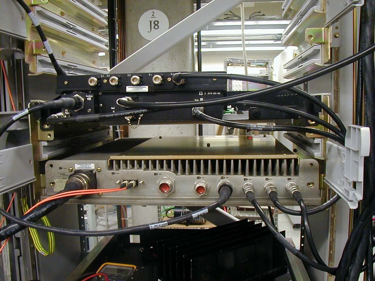
Click to zoom
Application Details
- Equipment Class
- TNB - Licensed Non-Broadcast Station Transmitter
- Date of Grant
- Dec 17, 2002
- Application Purpose
- Original Equipment
- Date of Application
- Dec 17, 2002
- Equipment Note
- CDMA Cellular Base Station
- Frequency Range
- 881.13000000 - 888.90000000
- Company
- Avaya Canada Corporation
- Country
- Canada
Documents & Files
Document Text
Text extracted from the exhibit documents filed with the FCC. Open a document above to read the original.
Cover Letter(s)
Request for Confidentiality Dec 6, 2002 American Telecommunications Certification Body, Inc. 6731 Whittier Avenue Suite C110 McLean, VA 22101 RE : Original Equipment Certification Application FCC Tx ID : AB6NT800MFRM2 Dear Sir/Madam Please accept this request for confidentiality of sensitive information contained in this application. The request for confidentiality applies to the following sections: EXHIBIT 3: Technical Description EXHIBIT 6: Internal Photos EXHIBIT 8A: Schematics (NTGY32AA pg 1-25) EXHIBIT 8B: Schematics (NTGY32AA pg 26-50) EXHIBIT 8C: Schematics (NTGY32AA pg 50-76) EXHIBIT 8D: Schematics (NTGY33AA, NTGY35AA, and NTGY38AA) EXHIBIT 9: Parts Lists (NTGY32AA, 33AA, 35AA, 38AA) EXHIBIT 11: User Manual The application contains technical information that Nortel Networks deems to be trade secrets and proprietary. If made public, the information might be used to the disadvantage of the applicant in the market place. Thank you for your attention to this matter. Sincerely, Thomas Wong, Regulatory Prime Wireless Division, Nortel Networks Tel: 403-769-2425 Fax: 403-769-7806 Email: [email protected]
Cover Letter(s)
American Telecommunications Certification Body Inc. 6731 Whittier Ave, McLean, VA 22101 December 15, 2002 RE: FCC ID: AB6NT800MFRM2 Attention: Thomas Wong I have a few comments on this Application. 1 On page 12 of 68 in the Samnina Test report the set up drawing shows that a splitter was used to allow both a Power Meter and a Spectrum Analyzer to be connected to the device. This parallel path has the potential of causing erroneous readings due to a possible impedance mismatch conditions. What steps were taken to insure that any variation in readings was correctly accounted for due to this setup? 2 Please provide the manual for the application. If confidentiality is desired for the manual, please provide a revised request for confidentiality specifically mentioning the manual along with all other confidential items. Dennis Ward mailto:[email protected] The items indicated above must be submitted before processing can continue on the above referenced application. Failure to provide the requested information may result in application termination. Correspondence should be considered part of the permanent submission and may be viewed from the Internet after a Grant of Equipment Authorization is issued. Please do not respond to this correspondence using the email reply button. In order for your response to be processed expeditiously, you must submit your documents through the AmericanTCB.com website. Also, please note that partial responses increase processing time and should not be submitted. Any questions about the content of this correspondence should be directed to the sender.
Cover Letter(s)
Original Equipment Certification Application - Additional Information Dec 17, 2002 American Telecommunications Certification Body, Inc. 6731 Whittier Avenue Suite C110 McLean, VA 22101 RE : Original Equipment Certification Application FCC Tx ID : AB6NT800MFRM2 Dear Sir/Madam This letter is to respond the additional information that requested by ATCB. The answers to your requests are listed below: Question: 1 “On page 12 of 68 in the Samnina Test report the set up drawing shows that a splitter was used to allow both a Power Meter and a Spectrum Analyzer to be connected to the device. This parallel path has the potential of causing erroneous readings due to a possible impedance mismatch conditions. What steps were taken to insure that any variation in readings was correctly accounted for due to this setup?” Answer: Please see the attached letter from Sanmina for their responses. Question: 2 “Please provide the manual for the application. If confidentiality is desired for the manual, please provide a revised request for confidentiality specifically mentioning the manual along with all other confidential items.” The user manual has been submitted in with this letter. The revised “Request for Confidentiality” and “Certification Application” letters have also been updated to reflect the addition of the user manual (Exhibit 11). Please contact me for further information if necessary. Sincerely, Thomas Wong, Regulatory Prime Wireless Division, Nortel Networks Tel: 403-769-2425 Fax: 403-769-7806 Email: [email protected]
External Photos
This document contains Proprietary information of Nortel Networks. This information is considered to be confidential and should be treated appropriately. EXHIBIT 5 External Photos Applicant: Nortel Networks For Original Equipment Certification on: AB6NT800MFRM2 This document contains Proprietary information of Nortel Networks. This information is considered to be confidential and should be treated appropriately. Nortel Networks MFRM2 Assembly Front View Fan Assembly Mounted This document contains Proprietary information of Nortel Networks. This information is considered to be confidential and should be treated appropriately. Nortel Networks MFRM2 Assembly Front View Fan Assembly Removed
ID Label/Location Info
This document contains Proprietary information of Nortel Networks. This information is considered to be confidential and should be treated appropriately. EXHIBIT 4 Transmit Label Information Applicant: Nortel Networks For Original Equipment Certification on: AB6NT800MFRM2 This document contains Proprietary information of Nortel Networks. This information is considered to be confidential and should be treated appropriately. Nortel Networks AB6NT800MFRM2 FCC Tx ID Label This document contains Proprietary information of Nortel Networks. This information is considered to be confidential and should be treated appropriately. Nortel Networks AB6NT800MFRM2 FCC Tx ID Label Location
RF Exposure Info
This document contains Proprietary information of Nortel Networks. This information is considered to be confidential and should be treated appropriately. EXHIBIT 10 RF Exposure Guidelines for PCS and Cellular Applicant: Nortel Networks Inc. For Original Equipment Certification on: AB6NT800MFRM2 RF Exposure Guidelines for Cellular, PCS and LMDS Antenna Sites Document no: SI-EMR-R01.5 Authors: Product Integrity BWA – RF Engineering Microwave Radio Design Proprietary Northern Telecom Antenna Siting Guideline 3 The information disclosed herein is proprietary to Nortel Networks or others and is not to be used by or disclosed to unauthorized persons without the written consent of Nortel. The recipient of this document shall respect the security status of the information. 1.0 Executive Summary This document serves as a guideline for the deployment and installation of Nortel Networks’ wireless base station equipment with respect to the control of electromagnetic radiation (EMR) exposure. The objective is to provide guidance on where antennas can be deployed, how to calculate power densities and safe distances and how to protect users from excessive exposure to electromagnetic radiation. This guideline is in response to recent regulatory requirements originating in the US aimed at controlling human exposure to EMR. Safe distance formulae for base stations: Limits Application Uncontrolled r [ meters ] Controlled r [ meters ] Cellular r0. 300 ER P= r0. 135 ER P= PCS r0. 228 ER P= r= 0.102 ERP DCS r0. 228 ER P= r=0.102ERP LMDS r = 1 r = 0.4 P-to-P Microwave Radio r = 1 r = 0.4 Uncontrolled refers to situations where individuals are either unaware or not in control of their exposure to the electromagnetic fields in question. This typically pertains to the general public. Controlled refers to situations where individuals are both aware of and in control of their exposure to the electromagnetic fields in question. This typically pertains to trained staff that is in contact with these fields as a result of their employment and have authority to limit their exposure. Note: This document includes DCS in its examples. If the EU adopts ENV50166, or any other EMR standard, then that document will replace this as the guideline for DCS products. Until that happens, these limits can be used to ensure due diligence on Nortel Networks’ behalf. Northern Telecom Antenna Siting Guideline iv Table of Contents 1.0 Executive Summary ................................................................................. ii 2.0 Introduction ............................................................................................. 1 3.0 Guideline ............................................................................................. 2 3.1 MPE Limits ............................................................................................. 3 3.2 Safe Distance and Power Density Calculations ................................. 5 3.2.1 Minimum Safe Distance ............................................................ 6 3.2.2 Power Density Calculation ........................................................ 8 3.3 Site Planning ............................................................................................ 9 4.0 Other Components ................................................................................. 10 5.0 Assumptions ........................................................................................... 11 6.0 References .............................................................................................. 12 7.0 Acronyms ............................................................................................... 12 Northern Telecom Antenna Siting Guideline 1 2.0 Introduction Regulatory bodies in the US, Federal Communications Commission (FCC), and Canada, Health Canada, are imposing Maximum Permissible Exposure (MPE) limits. FCC’s OET Bulletin #65 (versions in progress) addresses calculation and measurement procedures to determine compliance with the FCC limits which includes the 800 MHz cellular and 1.9 GHz PCS bands. The equipment and its associated deployment must comply with FCC Guidelines, ET Docket No. 93-62, Released August 1, 1996, (FCC 96-326). This standard is largely based on the limits and test methods outlined in IEEE C95.1-1982, NCRP Report No. 86 and C95.3-1982 respectively. The applicable portions of both are summarized in this document to assist in the antenna site planning to ensure compliance. The exposure limits are currently in effect. The requirement for installers to evaluate the exposure at an installation takes effect on Sept. 1/97. The exposure limits should apply now to all known sites since existing facilities are not exempt or grand fathered from the new rules. The FCC has determined that certain sites will require “Environmental Evaluations” in order to show compliance to the standards. Adhering to these guidelines can ensure compliance to the standard, and therefore can be the basis for the Environmental Evaluation. Please note that some installations do not require such routine evaluation: exceptions are noted further in this document. Adherence to these guidelines is recommended to promote safety. An installation of equipment that is identified as exempt may require an Environmental Evaluation if the combined energy of other Radio Systems at the site and the new installation could reasonably exceed the safety limits. Environmental Evaluations are kept on hand, as opposed to file with the FCC, unless requested by the FCC for substantiation. Where Nortel Networks is responsible for installing or engineering base stations, the person in charge should be aware of and have access to documentation for making an Environmental Evaluation. Also, Nortel Networks will need to maintain documentation for assurances to the FCC that Environmental Evaluations have been conducted for each radio station that uses our Experimental Radio License, or STA, where the station…
Text truncated - open the document above for the full version.
Test Report
This document contains Proprietary information of Nortel Networks. This information is considered to be confidential and should be treated appropriately. EXHIBIT 2 Test Report Summary Applicant: Nortel Networks For Original Equipment Certification on: AB6NT800MFRM2 Test Report Summary for FCC Class II Permissive Change Equipment Authorization FCC ID : AB6NT800MFRM2 Multi-carrier Flexible Radio Module Document: TRS_AB6NT800MFRM2 Stream: 00 Issue: 01 Issue Date: Dec 06, 2002 Security Status: Nortel Networks Confidential Author: Thomas Wong 2002 Nortel Networks Limited Disclaimer The master of this document is stored on an electronic database and “write protected”. The protection can be altered by authorized persons only. Viewing of the master document electronically ensures access to the current issue. Any hardcopies must be regarded as uncontrolled copies. Security Warning The information disclosed herein is proprietary to Nortel Networks and not to be used by or disclosed by unauthorized persons without the written consent of Nortel Networks. The recipient of this document shall respect the security status of the information. Application for Class II Permissive Change Certification FCC ID: AB6NT800MFRM2 Prepared on Dec 6, 2002 Nortel Networks Confidential Page 1 1 Introduction This test report is submitted in accordance with the FCC Rules and Regulations, Part 2, Subpart J, Sections 2.1046 through 2.1057 for equipment authorization of Nortel Networks’ CDMA 800 MHz Multi-carrier Flexible Radio Module 2 (MFRM2). The 800 MHz MFRM2 is intended for use in the Domestic Public Cellular Radio Telecommunications Service and is designed in accordance with the following standards: • CFR 47, Part 22, Subpart H, Subpart H, Cellular Radiotelephone Service[1] • CFR 47, Part 2, Subpart J, Equipment Authorization Procedures - Equipment Authorization[2] • CFR 47, Part 24, Subpart E, Broadband Personal Communications Service [3] 1. Test Result Summary Table 1 summarizes the measurement results for the CDMA 800 MHz MFRM2. Table 1: Test Results Summary FCC Measurement Specification FCC Limit Specification Description Results Test(s) Conducted by Remarks 2.1046 22.913 RF Output Power Compliant Sanmina Canada ULC See Exhibit 2A 2.1047 22.901 Modulation Characteristics Not Applicable 2.1049 Occupied Bandwidth OBW = 1.263 MHz (one carrier) OBW = 2.467 MHz (two carriers) OBW = 3.694 MHz (three carriers) Sanmina Canada ULC See Exhibit 2A 2.1051, 2.1057 22.901, 24.238 Spurious Emission at Antenna Terminals Compliant Sanmina Canada ULC See Exhibit 2A 2.1053, 2.1057 22.901, 24.238 Field Strength of Spurious Radiation Compliant Sanmina Canada ULC See Exhibit 2B 2.1055 22.913 Frequency Stability Compliant Nortel Networks See Exhibit 2A Application for Class II Permissive Change Certification FCC ID: AB6NT800MFRM2 Prepared on Dec 6, 2002 Nortel Networks Confidential Page 2 2. Engineering Declaration The CDMA 800 MHz MFRM2 (Multi-carrier Flexible Radio 2) has been tested in accordance with the requirements contained in the Federal Communication Rules and Regulations Part 2, 22 and 24. To the best of my knowledge, these tests were performed in accordance with good engineering practices using measurement procedures consistent with industry or commission standards or previous Commission correspondence or guidance and demonstrate that this equipment complies with the appropriate standards. All tests (including tests performed by Sanmina Canada ULC) were conducted on a representative sample of the equipment for which type acceptance/certification is sought. Report Prepared by Thomas Wong Regulatory Prime Nortel Networks Calgary, Alberta Dec 06, 2002 Application for Class II Permissive Change Certification FCC ID: AB6NT800MFRM2 Prepared on Dec 6, 2002 Nortel Networks Confidential Page 3 3. Type Acceptance Application Requirements 3.1 Name of Applicant The applicant is Nortel Networks Inc. 3.2 Identification of Equipment The equipment in this application for type acceptance is the Nortel’s CDMA 800 MHz MFRM2 (Multi-carrier Flexible Radio Module 2). The 800MHz MFRM2 is marketed under the model number NT800MFRM2. The FCC ID number sought is AB6NT800MFRM2. 3.3 Quantity Production The 800 MHz MFRM2 will be produced in quantity. 3.4 Technical Description See Exhibit 3. 3.5 Type of Emissions The 800 MHz MFRM2 Assembly is designed to operate in digital mode. The emission type is F9W for CDMA mode. The emission designators are 1M25F9W (1 Channel), 2M50F9W (2 Channels) and 3M73F9W (3 Channels). Testing was conducted in single channel, two channel, and 3 channel mode to determine compliance. The emission designators were calculated based on requirements of FCC Rule Part 2, Subpart C - Emissions, section 2.201 and Section 2.202. 3.6 Frequency Range The 800 MHz MFRM2 operates in the 800 MHz cellular band where the operating frequency ranges are 824 – 849 MHz for the receiver and 869 - 894 MHz for the transmitter. The following table shows the CDMA channels within this band meeting FCC requirements (based on single carrier mode). Band CDMA Channel Number Transmitter Center Frequency Assignment for Base Station (MHz) Channel Meeting FCC Requirements A’’ 991-1023 869.040-870.000 Non-compliance 1-3 870.030-879.090 Non-compliance 4-296 870.120-878.880 Compliance A 297-333 878.910-879.990 Non-compliance 334-370 881.020-881.100 Non-compliance 371-630 881.130-888.900 Compliance B 631-666 888.930-889.980 Non-compliance A’ 667-716 890.010-891.480 Non-compliance Application for Class II Permissive Change Certification FCC ID: AB6NT800MFRM2 Prepared on Dec 6, 2002 Nortel Networks Confidential Page 4 717-753 891.510-892.590 Non-compliance 754-763 892.620-892.890 Compliance B’ 764-799 892.920-893.970 Non-compliance 3.7 Range of Operating Power The 800 MHz MFRM2 range of operating RF power is 0 dBm to 47.3 dBm . The maximum RF power output is 47.3 dBm.. 3.8 Complete Circuit Diagrams The Tx chain of the 800 MHz MFRM2 radio system for certification is ma…
Text truncated - open the document above for the full version.
Test Report
This document contains Proprietary information of Nortel Networks. This information is considered to be confidential and should be treated appropriately. EXHIBIT 2A Test Report Provided by Nortel Networks Applicant: Nortel Networks For Original Equipment Certification on: AB6NT800MFRM2 Method Title (maximum of 60 characters) / 1 Application for Type AcceptanceNortel Networks Inc FCC ID AB6NT800MFRM2Issue 1.0 1.0 Frequency Stability Equipment Application Requirements 1.1 Standard Test Conditions and Test Equipment The MFRM2 was tested under the following test conditions unless otherwise stated. • Ambient Temperature: 20 to 35 degrees C • Ambient Humidity:20 to 40% • DC supply Voltage:-48V Vdc and 24Vdc (Nominal) 1.2 EUT Identification List Table 1 shows the identification of the components used in measuring Frequency Stability. Table 1 - EUT Identification List UUT Equipment Description Make Release Number Serial Number 800MHz Radio Unit e/w:NTGY30AAR3NNTM533GRLAD MFRM2 Sub Module HCPANTGY82CAR1ASENAE000213 MFRM2 Sub Module MPEMADGY83CA03SMCLW0000100 2/ Method Title (maximum of 60 characters) Application for Type AcceptanceNortel Networks Inc FCC ID AB6NT800MFRM2Issue 1.0 2.0 Engineering Declaration We certify that the information and data contained in this report is accurate and valid for the intended testing of the Frequency Stability of the Nortel MFRM2 CDMA Radio module. Tested By: Harold Gill Hardware Design Engineer Nortel Networks Calgary, Canada Approved and Reviewed by By: Thomas Wong Regulatory Prime Nortel Networks Calgary, Canada Method Title (maximum of 60 characters) / 3 Application for Type AcceptanceNortel Networks Inc FCC ID AB6NT800MFRM2Issue 1.0 2.1 Test Equipment List Table 2 shows the identification of the test equipment used in this report. Table 2 - Test Equipment List Test Equipment Description Instrument Make Instrument Model Serial Number Calibration Due Date Vector Signal AnalyserAgilentE4406AUS390302459-Feb-2002 RF Power MeterAgilentE4419BUS3925043G29-Dec-2002 Radio RF Interface BoxSED38117assy1229 25.1 0002Verified RF SwitchDBP Microwave3SNHIP21-A902Verified AttenuatorWeinschl Corp48-30-43MJ785Verified RF CableTensolite64023RF314Verified RF CableA0775004Verified RF CableA0775004Verified RF CableA0775004Verified DC power supplyAgilent6674AUS3637201620-jan-2003 GPSTM GPS SourceNortelNTGY850AANNTM74TM2 74H N/A 4/ Method Title (maximum of 60 characters) Application for Type AcceptanceNortel Networks Inc FCC ID AB6NT800MFRM2Issue 1.0 3.0 FCC Requirements for Frequency Stability 3.1 FCC Part 2.1055 (a) The frequency stability shall be measured with variation of ambient temperature as follows: (1) From -30 to +50 centigrade for all equipment except that specified in subparagraphs (2) and (3) of this paragraph. (b) Frequency measurements shall be made at the extremes of the specified temperature range and at intervals of not more than 10 centigrade through the range. A period of time sufficient to sta- bilize all of the components of the oscillator circuit at each temperature level shall be allowed prior to frequency measurement. The short term transient effects on the frequency of the transmitter due to keying (except for broadcast transmitters) and any heating element cycling normally occur- ring at each ambient temperature level also shall be shown. Only the portion or portions of the transmitter containing the frequency determining and stabilizing circuitry need be subjected to the temperature variation test. (d) The frequency stability shall be measured with variation of primary supply voltage as follows: (1) Vary primary supply voltage from 85 to 115 percent of the nominal value for other than hand carried battery equipment. (3) The supply voltage shall be measured at the input to the cable normally provided with the equipment, or at the power supply terminals if cables are not normally provided. Effects on fre- quency of transmitter keying (except for broadcast transmitters) and any heating element cycling at the nominal supply voltage and at each extreme also shall be shown. (e) When deemed necessary, the Commission may require tests of frequency stability under con- ditions in addition to those specifically set out in paragraphs (a), (b), (c) and (d) of this section. (For example, measurements showing the effect of proximity to large metal objects, or of various types of antennas, may be required for portable equipment.) 3.2 FCC Part 22.355 Frequency Tolerance The carrier frequency of each transmitter in the 821-896MHz Frequency range, must be maintained within 1.5ppm tolerance, according to Table C-1 of this section. Method Title (maximum of 60 characters) / 5 Application for Type AcceptanceNortel Networks Inc FCC ID AB6NT800MFRM2Issue 1.0 3.3 Test Results Table 4 and Table 5 shows the results for Frequency stability versus temperature variation. Table 3 shows the results for Frequency versus Power Supply Voltage Table 3 - Test Results for Frequency Stability versus Power Supply Voltage Table 4 - Test Results for Frequency Stability versus Temperature for 24V operation Voltage (V) Maximum Carrier Frequency Deviation (ppm) Maximum Carrier Frequency Deviation (Hz) 10 MHz GPS Referenece (MHz) 40-0.0048-4.2210.000000 48 nominal0.00433.7910.000000 56-0.0023-2.0110.000000 200.00917.9910.000000 24 nominal-0.0057-4.9810.000000 280.00221.910.000000 Temperature ( o C) Maximum Carrier Frequency Deviation (ppm) Maximum Carrier Frequency Deviation (Hz) 10 MHz GPS Referenece (MHz) -30-0.0035-3.0910.000000 -20-0.0024-2.1210.000000 -100.00171.4610.000000 00.00020.1510.000000 100.00131.1610.000000 20-0.0057-4.9810.000000 300.00020.1910.000000 400.00060.5110.000000 50-0.0019-1.6410.000000 6/ Method Title (maximum of 60 characters) Application for Type AcceptanceNortel Networks Inc FCC ID AB6NT800MFRM2Issue 1.0 Table 5 - Test Results for Frequency Stability versus Temperature for 48V operation The maximum frequency deviation was found to be0.0091 ppm (7.99 Hz). This deviation …
Text truncated - open the document above for the full version.
Test Report
This document contains Proprietary information of Nortel Networks. This information is considered to be confidential and should be treated appropriately. EXHIBIT 2B Test Report Provided by Sanmina-SCI Applicant: Nortel Networks For Original Equipment Certification on: AB6NT800MFRM2 This document contains Proprietary Information of Sanmina- SCI This information is considered to be CONFIDENTIAL and should be treated appropriately. Product Integrity Laboratory 5151 -47 th Street, NE Calgary, Alberta T3J 3R2 Tel: (403) 295 5134 Fax : (403) 295 4091 FCC Part 22, Subpart H Compliance Test Report Project Code PI80210 CDMA 800 MHz Multicarrier Flexible Radio Module 2 (MFRM 2) Revision: 2.0 Date: December 10, 2002 Prepared for:Northern Telecom (Nortel Networks). Authors:Adrian Wong Glen Moore Approved by:Glen Moore EMC Manager Confidentially Statement: The information contained in this document is the property of Sanmina-SCI Corporation. Except as specifically authorized in writing by the Director of Sanmina-SCI Corporation, the holder of this document shall keep all information contained herein confidential and shall protect the same, in whole or in part, from disclosure and dissemination to all third parties. Application for Type AcceptanceDate: December 10, 2002 FCC ID: AB6NT800MFRM2Page 2-2 This document contains Proprietary Information of Sanmina- SCI This information is considered to be CONFIDENTIAL and should be treated appropriately. Document Revision Control ReleaseRelease AuthorReason for ChangeDate of Issue 1.0Adrian WongOriginal releaseDecember 9, 2002 2.0Adrian WongEdits based on Thomas Wong’s inputDecember 10, 2002 Please Note that Revision bars are not used. Application for Type AcceptanceDate: December 10, 2002 FCC ID: AB6NT800MFRM2Page 2-3 This document contains Proprietary Informat ion. This information is considered to be CONFIDENTIAL and should be treated appropriately. 1 Introduction This information is submitted in accordance with the FCC rules and regulations, Part 2, Subpart J, §2.1033 through §2.1057 and Industry Canada RSS 129 radio standard for Type Acceptance/Certification of the Northern Telecom’s (Nortel Networks) CDMA 800 MHz Multicarrier Flexible Radio Module 2 (MFRM 2) This 800 MHz MFRM 2 is intended for use in the Domestic Public Cellular Radio Telecommunications Service and is designed in accordance with the following standards: • CFR 47, Part 22, Subpart H, Domestic Public Cellular Radio Telecommunications Service • TIA/EIA/IS-95-A, Mobile Station - Base Station Compatibility Standard for Dual-Mode Wideband Spread Spectrum Cellular System, May 1995 Test Result Summary Table 1 summarizes the measurement results for the CDMA 800 MHz MFRM for 1, 2 and 3 Carrier configurations. Table 1: Test Results Summary FCC Measurement Specification FCC Limit Specification DescriptionResult 2.104622.913RF Output PowerCompliant 2.104722.901Modulation CharacteristicsNot Applicable 2.104922.917Occupied BandwidthOBW = 1.263 MHz (1 Channel) OBW = 2.469 MHz (2 Channels) OBW = 3.679 MHz (3 Channels) 2.1051, 2.105722.917Spurious Emissions at Antenna Terminals Compliant 2.1053, 2.105722.917Field Strength of Spurious EmissionsCompliant 2.1055Frequency StabilityN/A Application for Type AcceptanceDate: December 10, 2002 FCC ID: AB6NT800MFRM2Page 2-4 This document contains Proprietary Informat ion. This information is considered to be CONFIDENTIAL and should be treated appropriately. 2 Engineering Declaration The CDMA 800 MHz Multicarrier Flexible Radio Module 2 (MFRM 2) has been tested in accordance with the requirements contained in the Federal Communications Commission Rules and Regulations Parts 2 and 22 and Industry Canada Radio Standard Specification 129, issue 2, as directed by Nortel Networks. To the best of my knowledge, these tests were performed in accordance with good engineering practices using measurement procedures consistent with industry or commission standards or previous Commission correspondence or guidance and demonstrate that this equipment complies with the appropriate standards. All tests were conducted on a representative sample of the equipment for which type acceptance/certification is sought based on information provided by Nortel Networks. Tested By:_______________December 10, 2002 SignatureDate Shankara Malwes Sanmina-SCI Calgary, Alberta Reviewed By:_______________December 10, 2002 SignatureDate Glen Moore, Technical Manager EMC/RF Services Sanmina-SCI Calgary, Alberta Digitally signed by Shankara Malwes DN: cn=Shankara Malwes, o=Sanmina-sci, c=CA Date: 2002.12.10 10:59:43 -07'00' Signature Not Verified Digitally signed by Glen Moore DN: cn=Glen Moore, o=Sanmina-SCI, c=CA Date: 2002.12.10 11:05:28 -07'00' Reason: I have reviewed this document Signature Not Verified Application for Type AcceptanceDate: December 10, 2002 FCC ID: AB6NT800MFRM2Page 2-5 This document contains Proprietary Informat ion. This information is considered to be CONFIDENTIAL and should be treated appropriately. 3.0EUT Description 3.1Name of Applicant The applicant is Northern Telecom (Nortel Networks) Limited. 3.2Identification of Equipment The equipment in this application for type acceptance is the Northern Telecom’s (Nortel’s) CDMA 800 MHz Multicarrier Flexible Radio Module 2 (MFRM 2). The 800 MHz MFRM 2 will be marketed under the model number NT800MFRM2. The FCC ID number sought is AB6NT800MFRM2. 3.3Quantity Production The 800 MHz MFRM 2 will be produced in quantity. 3.4Technical Description See Exhibits. 3.5Types of Emissions The 800 MHz MFRM 2 Assembly is designed to operate in digital mode. The emission type is F9W for CDMA mode. The emission designator is 1M25F9W(1 Channel), 2M50F9W (2 Channel and 3M73F9W (3 Channel). Testing was conducted in single channel mode, two channel and 3 channel mode to determine compliance. The emission designators were based on requirements of FCC Rule Part 2, Subpart C – Emission, Section 2.201 and Section 2.202. For Single Carrier mode: 1M25F9W – 1.25…
Text truncated - open the document above for the full version.
Test Setup Photos
This document contains Proprietary information of Nortel Networks. This information is considered to be confidential and should be treated appropriately. EXHIBIT 7 Test Setup Photos Applicant: Nortel Networks For Original Equipment Certification on: AB6NT800MFRM2 This document contains Proprietary information of Nortel Networks. This inform…
Text truncated - open the document above for the full version.
Contact Information
Applicant
Gwendolyn Faino(Legal Director)
Technical Contact
Non-Technical Contact
Nortel Networks Inc.Thomas Wong
[email protected]403-769-2425
Test Firm
National Technical Systems (NTS)Nick Kobrosly
Technical Specifications
| # | Rule Parts | Frequency Range | Power Output | Emission | Tolerance |
|---|---|---|---|---|---|
| 7 | 22.901(d) | 881.13 MHz - 888.9 MHz | 53.7 W | 3M73F9W | 0.0091 ppm |
Other Applications from Avaya Canada Corporation

AB6NT2100V3231
Mar 30, 2008AWS Radio
Equipment Class
TNB - Licensed Non-Broadcast Station Transmitter
AB6BTS9000
Dec 19, 2007Base Transceiver Station
Equipment Class
PCB - PCS Licensed Transmitter
AB6NT2100MFRM3
Oct 10, 2007NT2100 MFR M3 AWS radio
Equipment Class
TNB - Licensed Non-Broadcast Station Transmitter
AB6NTQ220AB
Jun 12, 2007NTQ220ABE5 Radio Module
Equipment Class
TNB - Licensed Non-Broadcast Station Transmitter
AB6BTS6000D
Jun 07, 2007GSM 6000 Base Transceiver Station
Equipment Class
PCB - PCS Licensed Transmitter