AB6NTGS09AA800 MHz CDMA Adjunct System
Avaya Canada Corporation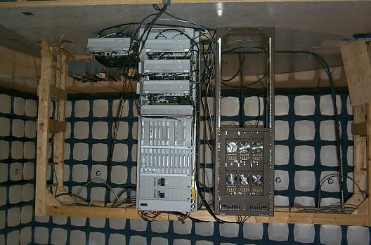
Click to zoom
Application Details
- Equipment Class
- PCB - PCS Licensed Transmitter
- Date of Grant
- Sep 14, 1999
- Application Purpose
- Original Equipment
- Date of Application
- Jun 02, 1999
- Equipment Note
- 800 MHz CDMA Adjunct System
- Frequency Range
- 869.04000000 - 893.97000000
- Company
- Avaya Canada Corporation
- Country
- Canada
Documents & Files
Document Text
Text extracted from the exhibit documents filed with the FCC. Open a document above to read the original.
Users Manual
This document contains Proprietary Information of Northern Telecom Limited. This information is considered to be CONFIDENTIAL and should be treated appropriately. EXHIBIT 3 User Documentation Applicant: Northern Telecom Ltd. For Type Acceptance/Certification on: AB6NTGS09AA This document contains Proprietary Information of Northern Telecom Limited. This information is considered to be CONFIDENTIAL and should be treated appropriately. Feasibility Study During a short feasibility study a number of issues were identified when the CDMA Metrocell is to be used with the MCPA shelf to deliver maximum 50W of output power per single CDMA carrier and 100W per two CDMA carriers measured at the MCPA shelf output port. A list of issues that is provided in this chapter is not complete and more issues are expected to be identified once design of the project is actively initiated. Each identified issue has been analyzed and current solutions are provided for each of the issues. Customer should provide +27V/240 Amps of current for 3 MCPA shelves. With this power level maximum 3 MCPA shelves will deliver maximum 100W per sector or 300W per all three sectors. Customer DC power and grounding strategy should meet Nortel and UL requirements for both CDMA Metrocell and TDMA radio frame. Design will specify the MCPA shelf DC power supply requirements and the customer will be responsible to procure the DC power supply that meets the specifications. If customer procured DC power supply will not meet the specified requirements the performance and reliability of the MCPA shelves could be degraded. TDMA radio frame is not capable to support more than 2 MCPA shelves. Either two TDMA radio frames are to be used or additional RIP is to be installed in the same TDMA radio frame. Furthermore, customer could provide breakers and power cables for each MCPA shelf in order to limit a number of TDMA radio frames. One TDMA radio frame will be limited to support 2 MCPA shelves. One RIP with 6 breakers, 50W each, will be used for one TDMA radio frame. CDMA Metrocell customer alarms will require to develop an Alarm Box that will convert the MCPA shelf alarm logic to the CDMA Metrocell appropriate alarm logic. No MCPA shelf alarms will be available with the CDMA Metrocell. The customer might be able to support the MCPA shelf alarms via the AMPS equipment, however design is not responsible to either verify or support the MCPA shelf alarms with the AMPS equipment. Field calibration procedure will be required to ensure that the MCPA shelf is set to the correct output power level. The accuracy of the calibration procedure will be limited by the accuracy of the calibration equipment, MCPA shelf power detector, CDMA Metrocell HIPD as well as attenuator and cable absolute loss variation over the operational temperature. No additional information is available. CDMA Metrocell system reported transmitted output power will not be correct as the power level reported by the CDMA Metrocell will be derived based on the 25W SCPA with reference to the DPM ANT port. No additional information is available. This document contains Proprietary Information of Northern Telecom Limited. This information is considered to be CONFIDENTIAL and should be treated appropriately. Receiver sensitivity and/or IIP3 will be somewhat impacted if the transmit signal after the MCPA shelf is to be transmitted via the same DPM that is used to filter and amplify the receive signal. No additional information is available. Receiver sensitivity and/or IIP3 will be impacted for configurations where CDMA Metrocell receive signals will be shared with AMPS systems, especially after passing via the AMPS multicouplers. Excel spreadsheet is available to calculate the CDMA Metrocell degradation with the AMPS multicouplers in-line. 20 dB 150W power attenuators will require to be mounted in the TDMA radio frame where sufficient airflow is available for cooling purposes. It is recommended to mount the fixed attenuators at the back of the MCPA shelf for modular design and easy accessibility. If thermal or other mechanical issues will be identified, the fixed attenuators will be mounted below the MCPA shelves in the TDMA radio frame. Variable attenuators will require to be mounted in the TDMA radio frame, possibly in close proximity to the MCPA shelf. In addition, variable attenuators will have to be easily accessible for calibration purposes in the field. It is recommended to mount the variable attenuators at the back of the MCPA shelf for modular design and easy accessibility. If thermal or other mechanical issues will be identified, the variable attenuators will be mounted below the MCPA shelves in the TDMA radio frame. A number of new RF and DC cables will be required to interface the CDMA Metrocell with the TDMA radio frame and MCPA shelf. Development will first try to reuse currently designed and available cables from the CDMA product portfolio. It is recommended to provision a directional coupler at the output of the MCPA in order to monitor the output power with the external power meter when the system is operational as well as during the calibration process. This will ensure that the cable between the MCPA shelf output and the duplexer will not be taken off every single time during the calibration. No additional information is available. This document contains Proprietary Information of Northern Telecom Limited. This information is considered to be CONFIDENTIAL and should be treated appropriately. Block Level Diagrams This chapter provides three high level block diagrams that are given in Figure 1, Figure 2 and Figure 3 for the 800 MHz CDMA Metrocell that are being examined to provide 100W of RF power at the MCPA shelf output for 2 CDMA carriers with one or two antennas per sector. In the first case it was assumed that the CDMA Metrocell and the TDMA radio frame are separated by some distance and the receive signals for the CDMA Metrocell are provided from AMPS mupticouplers. In …
Text truncated - open the document above for the full version.
Cover Letter(s)
Wireless Development Center, 2 nd Floor, 2924 11 Street NE, Calgary, Alberta, Canada, T2E 7L7 Logi Balasingham Ph: (403) 232-4864 Fax: (403) 232-4813 Email: [email protected] June 03, 1999 Federal Communications Commission Authorization & Evaluation Division Equipment Authorization Branch 7435 Oakland Mills Road Columbia, Maryland 21046 Subject: Part 22 Certification for the Nortel’s CDMA 800 MHz Adjunct System Form 731 Confirmation Number: EA94421 FCC ID:AB6NTGS09AA Dear Sir or Madam: Enclosed, in accordance with the FCC Part 22 rules, is Nortel Networks’ (Northern Telecom) test report for the 800 MHz CDMA Adjunct System, in support of the attached form 731 application for Certification. A completed Fee Form 159 is also included (will be mailed as noted in the Electronic Filing Instructions) for the amount of $450.00 representing the fee for this Certification. If there is any further information that I can provide to expedite this approval, please do not hesitate in contacting me directly. Sincerely, Logi Balasingham EMC/Radio Engineer
Cover Letter(s)
Application for Type AcceptancePrepared on: 21 May, 1999 FCC ID: AB6NTGS09AAPage i List of Exhibits Exhibit 1Label Identification Exhibit 2Test Report Exhibit 3User Documentation Exhibit 4System Photographs
External Photos
This document contains Proprietary Information of Northern Telecom Limited. This information is considered to be CONFIDENTIAL and should be treated appropriately. EXHIBIT 4 System Photographs Applicant: Northern Telecom Ltd. For Type Acceptance/Certification on: AB6NTGS09AA This document contains Proprietary Information of Northern Telecom Limited. This information is considered to be CONFIDENTIAL and should be treated appropriately. Figure 1: Front View of CDMA Digital Rack and TDMA RF Rack Figure 2: Rear View of both MCPA Shelves This document contains Proprietary Information of Northern Telecom Limited. This information is considered to be CONFIDENTIAL and should be treated appropriately. Figure 3: Rear View of the MCPA Shelf with Adjunct Kit Figure 4: Detailed Rear View of the Adjunct Kit
ID Label/Location Info
CONFIDENTIAL EXHIBIT 1 Label Identification Applicant: Northern Telecom Ltd. For Type Acceptance/Certification on: AB6NTGS09AA FCC ID: AB6NTGS09AAPage 1-1 CONFIDENTIAL Label Identification A drawing of the regulatory label is shown below: The contents of the label may be modified to also include safety regulatory logo such as UL and CSA. CDMA Metro Cell 800 Extreme FCC ID: AB6NTGS09AA FCC ID: AB6NTGS09AAPage 1-2 CONFIDENTIAL FCC ID: AB6NTGS09AAPage 1-3 CONFIDENTIAL Below photograph shows the rear side of the adjunct MCPA shelf. The regulatory label will be placed in approximately the position shown in the following picture. fl FCC Label will be attached on fl the right top bracket
Test Report
This document contains Proprietary Information of Northern Telecom Limited. This information is considered to be CONFIDENTIAL and should be treated appropriately. List of Exhibits Exhibit 1Label Identification Exhibit 2Test Report Exhibit 3User Documentation Exhibit 4System Photographs This document contains Proprietary Information of Northern Telecom Limited. This information is considered to be CONFIDENTIAL and should be treated appropriately. EXHIBIT 2 Test Report Applicant: Northern Telecom Ltd. For Type Acceptance/Certification on: AB6NTGS09AA Application for Type AcceptancePrepared on: 21 May 1999 FCC ID: AB6NTGS09AAPage 2-3 This document contains Proprietary Information of Northern Telecom Limited. This information is considered to be CONFIDENTIAL and should be treated appropriately. 1 Introduction This information is submitted in accordance with the FCC rules and regulations, Part 2, Subpart J, §2.1033 through §2.1057 and Industry Canada RSS 129 radio standard for Type Acceptance/Certification of the Northern Telecom’s (Nortel Networks) FCC approved CDMA 800 MHz Flexible Radio Module (FRM) adjunct with external multi channel amplifier(MCPA) configured in a TDMA rack. This adjunct system is intended for use in the Domestic Public Cellular Radio Telecommunications Service and is designed in accordance with the following standards: • CFR 47, Part 22, Subpart H, Domestic Public Cellular Radio Telecommunications Service • TIA/EIA/IS-95-A, Mobile Station - Base Station Compatibility Standard for Dual-Mode Wideband Spread Spectrum Cellular System, May 1995 1.1 Test Result Summary Table 1 summarizes the measurement results for the CDMA 800 MHz adjunct system. Table 1: Test Results Summary FCC Measurement Specification FCC Limit Specification DescriptionResult 2.104622.913RF Output PowerCompliant 2.104722.901Modulation CharacteristicsNot Applicable 2.104922.917Occupied BandwidthOBW = 1.266 MHz 2.1051, 2.105722.917Spurious Emissions at Antenna Terminals Compliant 2.1053, 2.105722.917Field Strength of Spurious EmissionsCompliant 2.1055Frequency StabilityCompliant Application for Type AcceptancePrepared on: 21 May 1999 FCC ID: AB6NTGS09AAPage 2-4 This document contains Proprietary Information of Northern Telecom Limited. This information is considered to be CONFIDENTIAL and should be treated appropriately. 2 Engineering Declaration The CDMA 800 MHz adjunct with external MCPA rack system has been tested in accordance with the requirements contained in the Federal Communications Commission Rules and Regulations Parts 2 and 22 and Industry Canada Radio Standard Specification 129, issue 1. To the best of my knowledge, these tests were performed in accordance with good engineering practices using measurement procedures consistent with industry or commission standards and demonstrate that this equipment complies with the appropriate standards. All tests were conducted on a representative sample of the equipment for which type acceptance/certification is sought. Signed Official copy kept on file by Nortel NetworksMay 20, 1998 Rupinder RandhawaDate Technical Manager Wireless Systems Integrity Nortel Networks Calgary, Alberta Application for Type AcceptancePrepared on: 21 May 1999 FCC ID: AB6NTGS09AAPage 2-5 This document contains Proprietary Information of Northern Telecom Limited. This information is considered to be CONFIDENTIAL and should be treated appropriately. 3 Type Acceptance Application Requirements 3.1 Name of Applicant The applicant is Northern Telecom (Nortel Networks) Limited. 3.2 Identification of Equipment The equipment in this application for type acceptance is the Northern Telecom’s (Nortel’s) CDMA 800 MHz adjunct with external MCPA. The adjunct kit consists of a 20 dB fixed attenuator, and a 20 dB variable attenuator. The output power of this product be tuned by Nortel site crew to make sure the output power will not be violating the FCC approval. The FRM and MCPA are regulatory approved by FCC under AB6NT800FRM and E675JS0025 respectively. The FCC ID number sought for this product is AB6NTGS09AA. The initial feasibility and verification process examined to ensure that TDMA MCPA shelf can be used with the CDMA Metrocell to deliver higher output power than is currently available with the CDMA Metrocell 25W SCPA. A single MCPA shelf with 3x50W MCPA units was tested to ensure that it could support 2 CDMA carriers delivering 100 W of RF power at the duplexer output of the MCPA shelf. The test results demonstrated that at room temperature single MCPA shelf could deliver, on average, 100 W of RF power while meeting IS-97A specifications of antenna terminal Conducted Spurious Emissions. 3.3 Technical Description The output power of the CDMA Metrocell PAM not be changed in any way. In addition, all global parameters of the CDMA Metrocell not be altered in any way to support MCPA shelf in conjunction with the CDMA Metrocell PAM. The TDMA radio frame supports maximum 2 MCPA shelves. Although there is room available to position an additional MCPA shelf with 3x50W MCPA units, a single RIP is designed to power up maximum 2 MCPA shelves. In order to support 2 carrier 3 sector CDMA Metrocell with 50W per carrier two TDMA radio frames are required. One TDMA radio frame should have 2 MCPA shelves whereas the second TDMA radio frame should have 1 MCPA shelf. Three sector two carrier TDMA radio frames are given in Exhibit 3. A single MCPA shelf with 3x50W MCPA units is expected to meet the following power requirements that are given in Table 5. DescriptionSpecificationUnits Minimum Input Power per Carrier10dBm Minimum Total Input Power13dBm Maximum Input Power per Carrier20dBm Maximum Total Input Power23dBm Maximum Output Power per47dBm Application for Type AcceptancePrepared on: 21 May 1999 FCC ID: AB6NTGS09AAPage 2-6 This document contains Proprietary Information of Northern Telecom Limited. This information is considered to be CONFIDENTIAL and should be treated appropriately. Carrier Maximum Tota…
Text truncated - open the document above for the full version.
Contact Information
Applicant
Gwendolyn Faino(Legal Director)
Technical Contact
Non-Technical Contact
Nortel NetworksJanet Johanntges
[email protected](403)232-4190
Technical Specifications
| # | Rule Parts | Frequency Range | Power Output | Emission | Tolerance |
|---|---|---|---|---|---|
| 1 | 22.901(d) | 869.04 MHz - 893.97 MHz | 50 W | 1M25FXW | 0.0008000000 ppm |
Other Applications from Avaya Canada Corporation

AB6NT2100V3231
Mar 30, 2008AWS Radio
Equipment Class
TNB - Licensed Non-Broadcast Station Transmitter
AB6BTS9000
Dec 19, 2007Base Transceiver Station
Equipment Class
PCB - PCS Licensed Transmitter
AB6NT2100MFRM3
Oct 10, 2007NT2100 MFR M3 AWS radio
Equipment Class
TNB - Licensed Non-Broadcast Station Transmitter
AB6NTQ220AB
Jun 12, 2007NTQ220ABE5 Radio Module
Equipment Class
TNB - Licensed Non-Broadcast Station Transmitter
AB6BTS6000D
Jun 07, 2007GSM 6000 Base Transceiver Station
Equipment Class
PCB - PCS Licensed Transmitter