AB6NTHV45AAWireless Link Maintenance Tool
Avaya Canada Corporation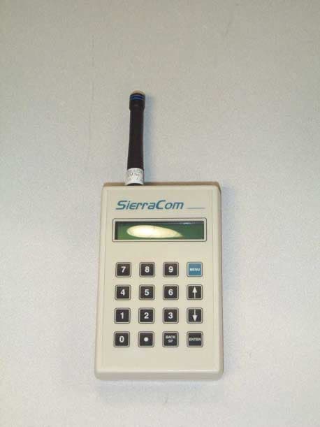
Click to zoom
Application Details
- Equipment Class
- DSC - Part 15 Security/Remote Control Transmitter
- Date of Grant
- Jan 14, 2001
- Application Purpose
- Original Equipment
- Date of Application
- Jan 14, 2001
- Equipment Note
- Wireless Link Maintenance Tool
- Frequency Range
- 418.00000000 - 418.00000000
- Company
- Avaya Canada Corporation
- Country
- Canada
Documents & Files
Document Text
Text extracted from the exhibit documents filed with the FCC. Open a document above to read the original.
Users Manual
APPENDIX B – HANDHELD OPERATION 1. Press <enter> to start handheld. 2. Handheld displays “enter address” 3. Enter address and press <enter>. 4. If ODU responds, asterisk goes on and message “link available” displays. 5. If ODU does not respond, message “no response. <enter> again.” Asterisk is off. The <enter> button can be pressed again without going back to entering the address. This allows the user to move around until a good link is established. 6. If link is available, pressing <menu> gets the “status” menu. Up/down arrows allow scrolling from “status” to “control”, etc. 7. Pressing <enter> will bring up the first data item within the sub-menus. Up/down arrows allow item scrolling. 8. At each sub-menu item, pressing <enter> will interrogate ODU for a new data item update. If data was not successfully received, the asterisk will extinguish. Asterisk will go on if data is received. Asterisk should be constant. 9. Data will not be automatically updated. New data is received only after each press of the <enter> button. This includes RSSI and BER. APPENDIX C – HANDHELD TRANSMISSION DATA FORMAT MENUCOMMAND Tx FreqS1S2S3S43107CS Rx FreqS1S2S3S43207CS Tx PowerS1S2S3S433 07CS FAWS1S2S3S434 07CS CapacityS1S2S3S43507CS Cable LengthS1S2S3S43607CS Line CodeS1S2S3S43707CS Trib on/offS1S2S3S438 07CS Mute on/offS1S2S3S43D07CS StatusLocal loopbackS1S2S3S44007CS RF LoopbackS1S2S3S44107CS Remote LoopbackS1S2S3S44207CS Tx Freq RangeS1S2S3S44A07CS Rx Freq RangeS1S2S3S44B07CS RSSIS1S2S3S44E07CS TemperatureS1S2S3S44F07CS Block Error CountS1S2S3S45007CS Summary AlarmsS1S2S3S45107CS Tx FreqS1S2S3S4000BVDVDVDVDCS Rx FreqS1S2S3S4010BVDVDVDVDCS PowerS1S2S3S402 08VDCS Local FAWS1S2S3S403 08VDCS ControlCapacityS1S2S3S40408VDCS Cable LengthS1S2S3S40508VDCS Line CodeS1S2S3S40608VDCS Tributary on/offS1S2S3S40708VDCS FarFar Line CodeS1S2S3S42108VDCS ControlFar Trib on/offS1S2S3S42208VDCS Link FreqsS1S2S3S42C08VDCS LinkLink Tx PowerS1S2S3S42D08VDCS ControlLink FAWS1S2S3S42E08VDCS Link CapacityS1S2S3S42F08VDCS PECS1S2S3S44407CS Prod. Rel. Ver.S1S2S3S44707CS InventorySerial No.S1S2S3S448 07CS DSP SW Ver.S1S2S3S44D07CS ODU SW Ver.S1S2S3S44C07CS Set MuteS1S2S3S40807CS TestSet Local LoopbkS1S2S3S41007CS Set RF LoopbackS1S2S3S41107CS Set Rem LoopbkS1S2S3S41207CS Power Off Handheld Contrast Software Ver. No Transmission DATA No Transmission No Transmission Notes: S1 through S4 vary according to binary value of serial number entered at handheld. VD indicates data that varies according to data entered at handheld keypad. CS indicates checksum value. All Byte values in hex Each byte includes one start bit, 8 data bits, one parity bit, one stop bit. APPENDIX D – ODU TRANSMISSION DATA FORMAT S1 – S4 contains the ODU address VD = variable data FS = field separator byte COMMAND RECEIVED Get Tx FrequencyS1 S2 S3 S4 3110VD VD VDVDFSVD VD VD VD CS Get Rx FrequencyS1 S2 S3 S4 3210VD VD VDVDFSVD VD VD VD CS Get Tx PowerS1S2S3S4 33 0A VD FS VD CS Get FAWS1S2S3S4 34 0A VD FS VD CS Get CapacityS1 S2 S3 S4 35 0A VD FSVDCS Get Cable LengthS1 S2 S3 S4 36 0C VD VDFSVDVDCS Get Line CodeS1 S2 S3 S4 37 0A VD FS VDCS Get Tributary on/offS1 S2 S3 S4 38 0A VD FS VDCS Get Mute on/offS1 S2 S3 S4 3D 0A VD FS VDCS Get Local LoopbackS1 S2 S3 S4 40 0A VD FS VDCS Get RF loopbackS1 S2 S3 S4 41 0A VD FS VDCS Get Rem loopbackS1 S2 S3 S4 42 0A VD FS VDCS Get Tx Freq RangeS1S2S3S44A 18 VDVD VD VD VD VD VDVD FS VD VDVDVDVDVDVDVDCS Get Rx Freq RangeS1 S2 S3 S4 4B 18VD CS VDVDVDVD VD VD FS VD VD VD VD VD VD VD VD CS Get RSSIS1 S2 S3 S4 4E 0A VD FS VDCS Get TemperatureS1 S2 S3 S4 4F 0AVD FSVDCS Get Block error countS1 S2 S3 S4 50 0C VD VD FSVDVDCS Get Summary alarmsS1 S2 S3 S4 5110VD VD VDVDFSVD VD VD VD CS Set Far End Line codeS1 S2 S3 S4 2108VD CS Set Far End Trib on/offS1 S2 S3 S4 2208VD CS Set link freqsS1S2S3S4 2C 0F VD VD VD VD VD VD VD VD CS Set link Tx powerS1 S2 S3 S4 2D 08VD CS Set link FAWS1S2S3S4 2E 08 VD CS Set link capacityS1 S2 S3 S4 2F08VD CS Get PECS1 S2 S3 S4 4420VD VD VDVDVDVD VD VD VD VD VD VD FS VD VD VD VD VD VD VD VD VD VD VD VD CS Get Prod Rel VerS1S2S3S447 20 VDVD VD VD VD VD VDVDVD VD VDVDFSVDVDVDVDVDVDVDVDVDVDVDVDCS Get Serial No.S1S2S3S448 20 VDVD VD VD VD VD VDVDVD VD VDVDFSVDVDVDVDVDVDVDVDVDVDVDVDCS Get Tx freq rangeS1S2S3S44A 18 VDVD VD VD VD VD VDVD FS VD VDVDVDVDVDVDVDCS Get Rx Freq rangeS1 S2 S3 S4 4B 18VD VD VDVDVDVD VD VD FS VD VD VD VD VD VD VD VD CS Get ODU SW ver.S1 S2 S3 S4 4C 0C VD VD FSVDVDCS Get DSP SW VerS1 S2 S3 S4 4D 0A VD FS VDCS Set Tx FreqS1 S2 S3 S4 00 0B VD VD VDVDCS Set Rx FreqS1 S2 S3 S4 01 0B VD VD VDVDCS Set Tx PowerS1 S2 S3 S4 0208VD CS Set FAWS1S2S3S4 03 08 VD CS Set CapacityS1 S2 S3 S4 0408VD CS Set Cable lengthS1 S2 S3 S4 0509VD VD CS Set Line codeS1 S2 S3 S4 0608VD CS Set Tributary on/offS1 S2 S3 S4 0708VD CS set mute on/offS1 S2 S3 S4 0C 08VD CS Set local loopbackS1 S2 S3 S4 1008VD CS Set RF LoopbackS1 S2 S3 S4 1108VD CS Set Remote loopbackS1 S2 S3 S4 1208VD CS DAT A CS = packet checksum All Byte values in hex. Each byte includes one start bit, 8 data bits, one parity bit, one stop bit. Data is transmitted only after receiving a request from handheld.
Attestation Statements
C-MAC Engineering 21 Richardson Side rd Kanata ON K2K 2C1 · Canada Tel 613 763 7847 Fax 613 763 8091 www.cmac.com January 4, 2001 Denis Lalonde Radio Compliance Specialist. American TCB, Inc. 6731 Whittier Avenue Suite C110 McLean, VA 22101 Re: AB6NTHV45AA Dear Sir or Madam: The antenna used in the iBWA System 3200 Hand Held Terminal (HHT) is manufactured by Antenna Factor, it’s model number is ANT-418-CW-HD. It is a reduced height ¼ wave antenna. The connector type of the antenna is reverse polarity SMA. The iBWA System 3200 HHT will be used by telecommunications technicians who are responsible for the maintenance and operations of the iBWA System 3200 Microwave Point-to-Point radios (FCCIDs:AB6NTHV5XD and AB6NTHV5XG). The HHT will not be marketed to the general public. Please call me or write if you have any questions or comments. Regards, Denis Lalonde Product Integrity email: [email protected] C-MAC Engineering
Cover Letter(s)
C-MAC Engineering 21 Richardson Side rd Kanata ON K2K 2C1 · Canada Tel 613 763 7847 Fax 613 763 8091 www.cmac.com December 11, 2000 Denis Lalonde Radio Compliance Specialist. American TCB, Inc. 6731 Whittier Avenue Suite C110 McLean, VA 22101 Re: AB6NTHV45AA Dear Sir or Madam: This is a Part 15 application for the Nortel Networks iBWA System 3200 Hand Held Terminal (HHT) that operates at 418 MHz. The FCCID of this equipment is AB6NTHV45AA. The iBWA System 3200 HHT will be used by telecommunications technicians who are responsible for the maintenance and operations of the iBWA System 3200 Microwave Point-to-Point radios (FCCIDs:AB6NTHV5XD and AB6NTHV5XG). The function of the HHT is to permit the remote control and monitoring of the microwave radios (typically installed on a tower) from the ground level. The HHT will not be marketed to the general public. Nortel Networks requests, pursuant to 47 CFR 0.457 and 0.459 of the commission's rules, that the following items be held CONFIDENTIAL due to their proprietary nature. Nortel Networks considers this leading edge technology developed by Nortel and its partners and being new technology, would not want to make this information available to its competitors. Exhibit 1. Schematics 2. Block Diagrams 3. Parts list Please call me or write if you have any questions or comments. Regards, Denis Lalonde Product Integrity email: [email protected] C-MAC Engineering
Cover Letter(s)
C-MAC Engineering 21 Richardson Side rd Kanata ON K2K 2C1 · Canada Tel 613 763 7847 Fax 613 763 8091 www.cmac.com January 4, 2001 Denis Lalonde Radio Compliance Specialist. American TCB, Inc. 6731 Whittier Avenue Suite C110 McLean, VA 22101 Re: AB6NTHV45AA Dear Sir or Madam: Nortel Networks requests, pursuant to 47 CFR 0.457 and 0.459 of the commission's rules, that the following items be held CONFIDENTIAL due to their proprietary nature. Nortel Networks considers this leading edge technology developed by Nortel and its partners and being new technology, would not want to make this information available to its competitors. Exhibit 1. Schematics 2. Block Diagrams 3. Parts list Please call me or write if you have any questions or comments. Regards, Denis Lalonde Product Integrity email: [email protected] C-MAC Engineering
Cover Letter(s)
1 William Graff To:Denis Lalonde Subject:Nortel Networks AB6NTHV45AA Hand Held 15.231 Denis, I have taken a quick look at the file you uploaded yesterday, and have the following comments: 1.) Please provide separate confidentiality request from cover letter. 2.) Please provide better photographs for the internal photos. All RF shielding must be removed, and back as well as front of board must be photographed. Clarity must be clear and of sufficient detail to identify individual parts or sub assemblies. 3.) External photos must show front, back, and top (antenna side). Orthographic projection preferred. 4.) Please provide antenna description and/or attestation for 15.203 antenna requirement. Please be sure to identify antenna mount. 5.) There is no data presented for radiated spurious emissions to the 10th harmonic per 15.33. This is the preferred method for demonstrating compliance with the restricted bands of 15.205. Bill ~~~~~~~~~~~~~~~~~~~~~~~~~~~~~~~~ ~ William H. Graff, NARTE Certified ~ Vice President of Engineering ~ AmericanTCB, Inc. ~ 6731 Whittier Ave ~ McLean, VA 22101 ~ mailto:[email protected] ~ mobile mailto:[email protected] ~ Direct Phone: (480)317-0683 ~ Corporate Phone: (703)847-4700 ~ Corporate FAX: (703) 847-6888 ~~~~~~~~~~~~~~~~~~~~~~~~~~~~~~~~
Cover Letter(s)
January 15, 2001 American Telecommunications Certification Body, Inc. 6731 Whittier Avenue Suite C110 McLean, VA 22101 To Whom It May Concern: Please be advised that Nortel Networks authorizes Denis Lalonde from C-MAC Engineering to act on our behalf, until otherwise notified, for applications submitted to American Telecommunications Certification Body, Inc. (ATCB). We certify that we are not subject to denial of federal benefits, that includes FCC benefits, pursuant to Section 5301 of the Anti-Drug Abuse ACT of 1988, U.S.C. 862. Further, no party, as defined in 47 CFR 1.2002(b), to the application is subject to denial of federal benefits, that includes FCC benefits. Thank you for your attention to this matter. Gilles Bois, Senior Manager, HW Development
External Photos
Nortel AB6NTHV45AA Hand Held External Photos Nortel AB6NTHV45AA Hand Held External Photos Nortel AB6NTHV45AA Hand Held External Photos Nortel AB6NTHV45AA Hand Held External Photos Nortel AB6NTHV45AA Hand Held External Photos
ID Label/Location Info
Location for the Label Hand Held Rear View
ID Label/Location Info
PROPRIETY INFORMATION : THE INFORMATION CONTAINED IN THIS DOCUMENT IS THE PROPERTY OF NORTEL NETWORKS, EXCEPT AS SPECIFICALLY AUTHORIZED IN WRITING BY NORTEL NETWORKS. THE HOLDER OF THIS DOCUMENT SHALL (1) KEEP ALL INFORMATION HEREIN CONFIDENTIAL AND SHALL PROTECT SAME IN WHOLE OR IN PART FROM DISCLOSURE AND DISSEMI- NATION TO ALL THIRD PARTIES AND (2) USE SAME FOR OPERATING AND MAINTENANCE PURPOSES ONLY. TITLE REGULATORY LABEL SCALE FULL SHEET 1 OF 2 SIZE A DRAWING NUMBER P0HANHEL DESIGN AUTHORITY NORTEL NETWORKS INITIAL APPLICATION NTHV45AA ECD: 102- DATE: 10 DEC 2000 ISSUE 01 STREAM 00 APPRV’L KR DRAWN GG NOTES: 1. UNLESS OTHERWISE SPECIFIED, ALL DIMENSIONS ARE EXPRESSED IN INCHES. TOLERANCES SHALL BE; TWO DECIMAL PLACES= ± .01THREE DECIMAL PLACES= ± .005 ALL LABEL CORNERS SHALL HAVE A .03 RADIUS. 2. THIS DESIGN FILE WAS CREATED IN ACCORDANCE WITH STD. 1517.20. THE LABELS/ARTWORK SHALL MEET ALL THE REQUIREMENTS OF NPS-90942. 3. THE ARTWORK (SEE SHEET 2) SHALL BE PLOTTED AT A MINIMUM OF 1200 DPI. THE TEXT FONT SHALL BE;UNIVERS 67 CONDENSED BOLD 4. MATERIAL;..010 POLYCARBONATE PER R0115902 FINISH;VELVET/MATTE ADHESIVE;.002 PRESS SENSITIVE WITH PEEL-OFF LINER PER R0113138 5. NORTTEL NETWORKS OBSERVATIONAL STANDARDS FOR COLORING (CORP STD #2701.01): BACKGROUND;WHITE (S-33294) TEXT, LINES, LOGOS;BLACK (S-33154) NORTEL NETWORKS LOGO;NORTEL NETWORKS BLUE (S-33301) NORTEL NETWORKS 2.50 2.60 This device complies with Part 15 of the FCC Regu- lations. Operation is subject to the following rules: (1) This device may not cause harmful interference. (2) This device must accept any interference received, including interference that may cause undesired operation. Made in Canada P0919876 01/01 Internet BWA System 3200 Model #: NTHV45AA FCC ID:AB6NTHV45AA Input: -48V 3.0A THIS AREA FOR SUPPLIER I.D.
Internal Photos
Internal Photos Nortel AB6NTHV45AA Internal Photos Nortel AB6NTHV45AA Internal Photos Nortel AB6NTHV45AA Internal Photos Nortel AB6NTHV45AA Internal Photos Nortel AB6NTHV45AA
Operational Description
WIRELESS LINK FUNCTIONAL DESCRIPTION The handheld radio is provided as a maintenance tool for the iBAR 100 series of microwave radios manufactured by Nortel Networks. These microwave radios individually operate in the 18, 23 and 38 GHz bands and provide point-to-point connections suitable for carrying 1T1, 2T1 or 4T1 traffic. A typical use for these microwave radios is in cellular backhaul applications. The microwave radios are of a completely integrated design, having RF hardware, modem and power supply contained in one package. A single, shielded multipair cable is used to provide data, control and power connections to the microwave radio. Access to control functions and status parameters are provided by an RS-485 data interface which may be connected to the local network management interface. As an alternative, maintenance personnel may also access a subset of the microwave radio control parameters via a wireless link provided by the handheld radio. HANDHELD FUNCTIONAL DESCRIPTION The handheld communicates with the microwave radio via a low power wireless link operating at 418 MHz. The modulation format is 9.6 kb/s on-off keying (OOK) and the data format is a string of bytes consistent with the IEEE-1185 protocol wherein the first byte transmitted in a packet has the parity bit set to one as a start-of-message flag. All following bytes have the parity bit set to zero. A mark signal is represented as carrier off; a space is represented as carrier on. The handheld always initiates communication with the microwave radio and therefore is the master unit. The microwave radio will not respond unless it receives a previously assigned unique address together with a valid command. The transmitted message also contains a message length byte as well as a checksum byte to guard against reception of erroneous commands in the presence of noise or interference. Message lengths vary from a minimum of seven bytes to a maximum of 11 bytes, depending on the command issued. The format of the message transmitted from the handheld is illustrated in Appendix A. See Appendix C for details of the command set. Under no conditions will the transmit time exceed 128 milliseconds The handheld contains a numeric keypad for operator data entry and display scrolling. Before it can be used, the handheld must be activated by pressing and holding the “enter” key until the display illuminates. A serial number must then be entered before access to any status or control screens is permitted. The handheld will automatically shut itself off if no keypad entries are made within a one minute period. The handheld transmits one message for each operator entry session that is concluded by pressing the “enter” key. Operation of the handheld is described in Appendix B. HANDHELD HARDWARE DESCRIPTION A block diagram of the handheld hardware is shown in Fig. 1. Two printed circuit cards are used to contain the entire electronics: the RF assembly contains the transmitter and receiver integrated circuit and the Digital Assembly contains the digital control circuits and connectors to interface with the display module and keypad. The keypad is an assembly integral to the handheld case. These assemblies are powered by four size AA batteries. The antenna connection is through a reverse SMA connector attached to a captivated bracket internal to the case, also serving as the antenna counterpoise. The antenna is a 3.5 in. helical wound flexible monopole with a reverse SMA threaded connector. Peak RF power delivered to the antenna is -4.5 ±2.5 dBm. Receiver sensitivity is approximately –80 dBm. Figure 1 – Handheld Radio Block Diagram BPF (Bandpass Filter) The bandpass filter provides RF selectivity to reject unwanted signals beyond ±15 MHz from the center frequency. The filter is a discrete lumped element design having about 5 dB of insertion loss. RF IC Receive Section The receiver section is part of the RF integrated circuit containing a SAW filter at the antenna input connection to attenuate unwanted signals. The filter is followed by a high gain, sequentially- switched amplifier chain operating at the receiver input frequency. The output of the amplifier chain is fed to an envelope detector circuit whose output is low-pass filtered to remove noise and improve data SNR. The filtered waveform is processed by a data slicer to recover the received data. The output of the receiver module is fed to the digital assembly. A block diagram of the receiver IC is shown in Figure 2. The receiver module has no internal local oscillators or IF. An internal switching circuit operating at approximately 100 kHz is used to sequentially switch the internal amplifiers to allow high gain operation and prevent oscillation. Figure 2 – RF IC Receiver Block Diagram DIGITAL ASSY Micro- controller Display Keypad SAW DELAY LINE PULSE GEN AM DET LPFAMPAMPBPFAMPCOMP RF IN DATA OUT RF ASSY RF IC BPF. Transmit Section Receive Section Control RF IC Transmit Section The transmitter section is part of the RF integrated circuit containing a SAW oscillator operating at 418 MHz., followed by an amplifier that produces approximately one milliwatt of RF. The RF output is filtered with a SAW bandpass filter to attenuate the signal harmonic content. The oscillator is switched on by the transmit data from the Digital Assembly. When no data is being transmitted, the Transmit Module is powered off. A block diagram of the Transmitter IC is shown in Fig. 3. Figure 3 – RF IC Transmitter Block Diagram Digital Assembly The digital Assembly contains all the circuits necessary to interface with the keypad, display and the RF Assembly as well as the battery power switch. A 68HC11 microcontroller performs all the control functions as programmed by its embedded code. The master clock for the microcontroller operates at 3.686 MHz. Serial data is received from the RF Assembly and checked for an address header that matches the address entered by the operator at the beginning of the session. If corr…
Text truncated - open the document above for the full version.
Test Report
Master: ktlPT15231 Date: April 5, 2000 KTL Test Report:0R03011.3 Applicant:Nortel Networks 2351 Blvd. Alfred Nobel St. Laurent, Quebec H4S 2A9 Equipment Under Test:Portable Wireless Unit (E.U.T.) In Accordance With:FCC Part 15, Subpart C For Low Power Transmitters Operating Periodically In The Band 40.66 - 40.77 MHz And Above 70 MHz Tested By:KTL Ottawa Inc. 3325 River Road, R.R. 5 Ottawa, Ontario K1V 1H2 Authorized By: G. Westwell, Technologist Date:November 7, 2000 Total Number of Pages:18 Authorized Copy:Soft Copy KTL OttawaFCC PART 15, SUBPART C FOR LOW POWER TRANSMITTERS PROJECT NO.: 0R03011.3 EQUIPMENT: Portable Wireless Unit Page 2 of 18 Table of Contents Section 1. Summary of Test Results......................................................................................3 Section 2. Equipment Under Test (E.U.T.)...........................................................................5 Section 3. Transmission Requirements.................................................................................9 Section 4. Radiated Emissions.............................................................................................11 Section 5. Occupied Bandwidth..........................................................................................14 Section 6. Block Diagrams...................................................................................................16 Section 7. Test Equipment List...........................................................................................18 KTL OttawaFCC PART 15, SUBPART C FOR LOW POWER TRANSMITTERS PROJECT NO.: 0R03011.3 EQUIPMENT: Portable Wireless Unit Page 3 of 18 Section 1.Summary of Test Results General All measurements are traceable to national standards. These tests were conducted on a sample of the equipment for the purpose of demonstrating compliance with Part 15, Subpart C, Paragraph 15.231. All tests were conducted using measurement procedure ANSI C63.4-1992. Radiated emissions are made on an open area test site. A description of the test facility is on file with the FCC. New SubmissionProduction Unit Class II Permissive ChangePre-Production Unit DXT Equipment Code THIS TEST REPORT RELATES ONLY TO THE ITEM(S) TESTED. THE FOLLOWING DEVIATIONS FROM, ADDITIONS TO, OR EXCLUSIONS FROM THE TEST SPECIFICATIONS HAVE BEEN MADE. See “ Summary of Test Data”. NVLAP LAB CODE: 100351-0 TESTED BY: DATE: November 7, 2000 Russell Grant, Wireless Group Manager KTL Ottawa Inc. authorizes the above named company to reproduce this report provided it is reproduced in its entirety and for use by the company’s employees only. Any use which a third party makes of this report, or any reliance on or decisions to be made based on it, are the responsibility of such third parties. KTL Ottawa Inc. accepts no responsibility for damages, if any, suffered by any third party as a result of decisions made or actions based on this report. This report applies only to the items tested. KTL OttawaFCC PART 15, SUBPART C FOR LOW POWER TRANSMITTERS PROJECT NO.: 0R03011.3 EQUIPMENT: Portable Wireless Unit Page 4 of 18 Summary Of Test Data Name of TestPara. NumberResults Transmission Requirements15.231(a)Complies Radiated Emissions15.231(b)Complies Occupied Bandwidth15.231(c)Complies Frequency Tolerance15.231(d)Not Applicable Periodic Alternate Field Strength Requirements15.231(e)Not Applicable Powerline Conducted Emissions15.207Not Applicable Footnotes For N/A’s:Battery Powered KTL OttawaFCC PART 15, SUBPART C FOR LOW POWER TRANSMITTERS PROJECT NO.: 0R03011.3 EQUIPMENT: Portable Wireless Unit Page 5 of 18 Section 2.Equipment Under Test (E.U.T.) General Equipment Information Manufacturer: Nortel Networks Date Received In Laboratory: October 2, 2000 KTL Identification No.: Item #1 Frequency Range: 418 MHz Operating Frequency(ies) of Sample: 418 MHz Emission Designator: 83K0K1D Supply Power Requirement: Batteries Duty Cycle Calculation: 20 Log 100 167.17x = -21.8 dB KTL OttawaFCC PART 15, SUBPART C FOR LOW POWER TRANSMITTERS PROJECT NO.: 0R03011.3 EQUIPMENT: Portable Wireless Unit Page 6 of 18 KTL OttawaFCC PART 15, SUBPART C FOR LOW POWER TRANSMITTERS PROJECT NO.: 0R03011.3 EQUIPMENT: Portable Wireless Unit Page 7 of 18 KTL OttawaFCC PART 15, SUBPART C FOR LOW POWER TRANSMITTERS PROJECT NO.: 0R03011.3 EQUIPMENT: Portable Wireless Unit Page 8 of 18 KTL OttawaFCC PART 15, SUBPART C FOR LOW POWER TRANSMITTERS PROJECT NO.: 0R03011.3 EQUIPMENT: Portable Wireless Unit Page 9 of 18 Section 3.Transmission Requirements Para. No.: 15.231(a) Test Performed By: Russell GrantDate of Test: October 27, 2000 Minimum Standard:15.231(a) Continuous transmissions such as voice, video or data transmissions are not permitted. 15.231(a)(1) A manually operated transmitter shall employ a switch that will automatically deactivate the transmitter within not more than 5 seconds after being released. 15.231(a)(2) A transmitter activated automatically shall cease transmission within 5 seconds of activation. 15.231(a)(3) Periodic transmissions at regular pre-determined intervals are not permitted. However polling or supervisory transmissions to determine system integrity of transmitters used in security or safety applications are allowed if the periodic rate of transmission does not exceed one transmission of not more than one second duration per hour for each transmitter. 15.231(a)(4) Intentional radiators which are employed for radio control purposes during emergencies involving fire, security, and safety of life, when activated to signal an alarm, may operate during the pendency of the alarm. Test Results:Complies. Test Data:Compliance was determined by verification of technical specifications and a functional test on the equipment. KTL OttawaFCC PART 15, SUBPART C FOR LOW POWER TRANSMITTERS PROJECT NO.: 0R03011.3 EQUIPMENT: Portable Wireless Unit Page 10 of 18 Rationale for Compliance with Transmission Requirements 15.231(a)(1) : The transmitter is automatically deactivated …
Text truncated - open the document above for the full version.
Test Report
C-MAC Engineering 21 Richardson Side rd Kanata ON K2K 2C1 · Canada Tel 613 763 7847 Fax 613 763 8091 www.cmac.com January 4, 2001 Denis Lalonde Radio Compliance Specialist. American TCB, Inc. 6731 Whittier Avenue Suite C110 McLean, VA 22101 Re: AB6NTHV45AA Dear Sir or Madam: This letter contains the recorded data for the radiated emissions test results measured at 3m. Frequency (MHz) Measured value (dBuV/m) Limit (dBuV/m) at 3m 418.06 61.6 80.3 836.12 15.3 54 1254.18 -17.0 54 1672.24 5.6 54 2090.3 -0.3 54 2508.36 2.1 54 2926.42 0.2 54 3344.48 4.0 54 3762.54 7.3 54 4180.6 15.7 54 Please call me or write if you have any questions or comments. Regards, Denis Lalonde Product Integrity email: [email protected] C-MAC Engineering
Test Setup Photos
Radiated Photographs (Worst Case Configuration) Front View
Contact Information
Applicant
Gwendolyn Faino(Legal Director)
Technical Contact
Test Firm
Nortel NetworksStirling Cullen
Technical Specifications
| # | Rule Parts | Frequency Range | Power Output |
|---|---|---|---|
| 1 | 15.231 | 418 MHz - 418 MHz | - |
Other Applications from Avaya Canada Corporation

AB6NT2100V3231
Mar 30, 2008AWS Radio
Equipment Class
TNB - Licensed Non-Broadcast Station Transmitter
AB6BTS9000
Dec 19, 2007Base Transceiver Station
Equipment Class
PCB - PCS Licensed Transmitter
AB6NT2100MFRM3
Oct 10, 2007NT2100 MFR M3 AWS radio
Equipment Class
TNB - Licensed Non-Broadcast Station Transmitter
AB6NTQ220AB
Jun 12, 2007NTQ220ABE5 Radio Module
Equipment Class
TNB - Licensed Non-Broadcast Station Transmitter
AB6BTS6000D
Jun 07, 2007GSM 6000 Base Transceiver Station
Equipment Class
PCB - PCS Licensed Transmitter