AB6NTHV5XDIBWA System 3200 (18GHz)
Avaya Canada Corporation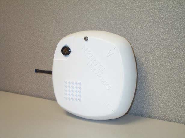
Click to zoom
Application Details
- Equipment Class
- TNB - Licensed Non-Broadcast Station Transmitter
- Date of Grant
- May 03, 2001
- Application Purpose
- Original Equipment
- Date of Application
- Jan 17, 2001
- Equipment Note
- IBWA System 3200 (18GHz)
- Frequency Range
- 17702.50000000 - 19697.50000000
- Company
- Avaya Canada Corporation
- Country
- Canada
Documents & Files
Document Text
Text extracted from the exhibit documents filed with the FCC. Open a document above to read the original.
Users Manual
NTXXXXXX Internet Broadband Wireless Access Internet BWA System 3200 User guide Draft Rel 3.0 October 2000 What’s inside... System description Ordering Information Technical specifications Trouble clearing procedures User interface description Installation and commissioning procedures Copyright 2000 Nortel Networks, All Rights Reserved The information contained herein is the property of Nortel Networks and is strictly confidential. Except as expressly authorized in writing by Nortel Networks, the holder shall keep all information contained herein confidential, shall disclose it only to its employees with a need to know, and shall protect it, in whole or in part, from disclosure and dissemination to third parties with the same degree of care it uses to protect its own confidential information, but with no less than reasonable care. Except as expressly authorized in writing by Nortel Networks, the holder is granted no rights to use the information contained herein. Nortel Networks, the Nortel Networks logo, the Globemark, How the World Shares Ideas, and Unified Networks are trademarks of Nortel Networks. Printed in Canada User guide NTXXXXXX Rel 3.0 Draft October 2000 iii Contents0 About this documentv System description1-1 Overview 1-1 Frequency band 1-1 Capacity 1-1 Frequency plan 1-2 System features 1-2 Equipment layout and main assemblies 1-3 Terminal signal flow 1-4 System interfaces 1-5 Interface cable pins 1-6 Hand-held terminal interface 1-6 Ordering Information2-1 Detailed equipment codes 2-1 Technical specifications3-1 Mechanical and environmental specifications 3-1 Equipment interface specifications 3-2 Frequency plan specifications 3-2 System performance specifications 3-3 Trouble clearing procedures4-1 Testing the Radio faults 4-1 RF Loopback test 4-1 Loopback test for the local tributary 4-1 Loopback test for the remote tributary 4-1 Clearing the Radio alarms 4-2 Alarm interface pins 4-4 Warranty and field support 4-5 Warranties 4-5 Standard return service 4-5 48-hour emergency service 4-7 Technical support and information 4-7 User interface description5-1 Hand-held terminal description 5-1 iv Contents Internet BWA System 3200 NTXXXXXX Rel 3.0 Draft October 2000 Hierarchy of the HHT menus 5-3 Functions of the HHT keypad keys 5-4 Parameters for the Near Radio menu 5-5 Control submenu 5-5 Status submenu 5-6 Inventory submenu 5-8 Test submenu 5-9 Parameters for the Far Radio menu 5-10 Control submenu 5-10 Parameters for the Link menu 5-10 Control submenu 5-10 Installation and commissioning procedures6-1 Chapter task list 6-1 List of procedures 6-1 Unpacking, identifying and matching the system 6-2 6-2 Installing the Internet BWA System 3200 on a pole 6-5 6-3 Connecting the interface cables 6-13 6-4 Setting up the Internet BWA System 3200 6-17 6-5 Aligning the antenna of the Internet BWA System 3200 6-20 6-6 Commissioning the Internet BWA System 3200 6-24 User guide NTXXXXXX Rel 3.0 Draft October 2000 v About this document0 This section provides an overview of the Internet BWA System 3200 user guide. Audience This document is intended for: •installers •system line-up and test (SLAT) engineers/technicians •maintenance engineers User interface conventions The following conventions are used in procedures in this document. boldBold entries identify a command or a userID entered by means of the craft interface terminal (CIT). ↵ ↵↵ ↵This symbol means the return key must be pressed. BoldBold entries with initial capital letters identify buttons, fields and menu items as seen on the user interface screen. vi About this document Internet BWA System 3200 NTXXXXXX Rel 3.0 Draft October 2000 User guide NTXXXXXX Rel 3.0 Draft October 2000 1-1 System description1- This document describes the Internet BWA System 3200. Overview The Internet BWA System 3200 establishes high-speed, reliable point-to-point wireless links. The Internet BWA System 3200 uses a 4-FSK modulation scheme and carries up to four E1 (2.048 Mbits/s) or up to four DS1 (1.544 Mbits/s) signals. Frequency band The Internet BWA System 3200 operates in the 15, 18, 23, 24/26, 28, 31 and 38 GHz frequency ranges. Capacity The capacity upgrade is software programmable from 2xE1 to 4xE1 and from 1xDS1 to 2xDS1 to 4xDS1. The capacity upgrade affects traffic because the upgrade changes the following parameters: •occupied bandwidth •receive baseband filters •data rate of operation Table 1-1 lists the bandwidths for the radio frequency (RF) channels. Table 1-1 RF channel bandwidths CapacityChannel bandwidth (MHz) 2 x E13.5 (for all frequencies) 4 x E17.0 (for all frequencies) 1 or 2 x DS12.5 (for all frequencies) 4 x DS15.0 (for all frequencies) 1-2 System description Internet BWA System 3200 NTXXXXXX Rel 3.0 Draft October 2000 For systems with a specific capacity (for example, a 4 x E1 capacity), the activation of a new tributary within that capacity is software programmable, either locally or remotely. The activation of a new tributary within an existing capacity does not cause any errors to the existing traffic. Inactive tributaries do not cause alarms. Frequency plan Frequency plans are in accordance with: •current ITU-R recommendations and annexes as applicable for international products •FCC rules, part 101 (as amended on October 1, 1997, replaces parts 21 and 94) •Industry Canada (SRSP-314.5, SRSP-318.5, SRSP-321.8) for North American products Table 1-2 lists the frequency plans. System features The Internet BWA System 3200 provides: •scalable channel capacity to precisely match traffic volume •scalable channel selection (digital synthesizer set in 250 kHz steps) •selectable AMI or B8ZS line coding for DS1 signals (E1 signals use HDB3 coding only) •selectable framing type (Unframe, Frame or ESF for DS1 signals) •hand-held wireless terminal to perform configuration, maintenance, and performance monitoring of the outdoor unit (ODU) •receive signal strength indicator (RSSI) on the outdoor unit to guide service personnel in antenna ali…
Text truncated - open the document above for the full version.
Cover Letter(s)
C-MAC Engineering 21 Richardson Side rd Kanata ON K2K 2C1 · Canada Tel 613 763 7847 Fax 613 763 8091 www.cmac.com December 1, 2000 Denis Lalonde Radio Compliance Specialist. American TCB, Inc. 6731 Whittier Avenue Suite C110 McLean, VA 22101 Re: AB6NTHV5XD Dear Sir or Madam: Nortel Networks requests, pursuant to 47 CFR 0.457 and 0.459 of the commission's rules, that the following items be held CONFIDENTIAL due to their proprietary nature. Nortel Networks considers this leading edge technology developed by Nortel and its partners and being new technology, would not want to make this information available to its competitors. Exhibit 1. Schematics 2. Block Diagrams Please call me or write if you have any questions or comments. Regards, Denis Lalonde Product Integrity email: [email protected] C-MAC Engineering
Cover Letter(s)
C-MAC Engineering 21 Richardson Side rd Kanata ON K2K 2C1 · Canada Tel 613 763 7847 Fax 613 763 8091 www.cmac.com December 1, 2000 Denis Lalonde Radio Compliance Specialist. American TCB, Inc. 6731 Whittier Avenue Suite C110 McLean, VA 22101 Re: AB6NTHV5XD Dear Sir or Madam: This is a Part 101 and Part 15 application for the Nortel Networks iBWA System 3200 that operates in the 18 GHz band. The FCCID of this equipment is AB6NTHV5XD. The Part 101 test report is for the 18 GHz transceiver contained in this equipment while the Part 15 test report is for a 418 MHz low power unlicensed transmitter which is also found in the equipment housing. The iBWA System 3200 (18 GHz) will be deployed on several frequency sub-bands within the 17.7 GHz to 19.7 GHz band. The only frequency dependent component of the iBWA System 3200 (18 GHz) is the diplexer. The product was tested without the diplexer in order to reduce the number of applications. The iBWA System 3200 (18 GHz) operates with several types of antenna: 60 cm,.90cm, and 120 cm diameter The gain of these antennas is between 39 dB and 44.9 dB. The maximum EIRP from the iBWA System 3200 (18 GHz) is therefore below 3090 W. A radiation hazard evaluation is included in the application. It demonstrates that the radio’s power density is below 1 mW/cm2 at any distance. Please call me or write if you have any questions or comments. Regards, Denis Lalonde Product Integrity email: [email protected] C-MAC Engineering
ID Label/Location Info
PROPRIETY INFORMATION: THE INFORMATION CONTAINED IN THIS DOCUMENT IS THE PROPERTY OF NORTEL NETWORKS, EXCEPT AS SPECIFICALLY AUTHORIZED IN WRITING BY NORTEL NETWORKS. THE HOLDER OF THIS DOCUMENT SHALL (1) KEEP ALL INFORMATION HEREIN CONFIDENTIAL AND SHALL PROTECT SAME IN WHOLE OR IN PART FROM DISCLOSURE AND DISSEMI- NATION TO ALL THIRD PARTIES AND (2) USE SAME FOR OPERATING AND MAINTENANCE PURPOSES ONLY. TITLE REGULATORY LABEL SCALE FULL SHEET 1OF 2 SIZE A DRAWING NUMBER P0919875 DESIGN AUTHORITY NORTEL NETWORKS INITIAL APPLICATION NTHV50DG ECD: 102- DATE: 31 OCT 2000 ISSUE 01 STREAM 00 APPRV’L AH DRAWN GG NOTES: 1. UNLESS OTHERWISE SPECIFIED, ALL DIMENSIONS ARE EXPRESSED IN INCHES. TOLERANCES SHALL BE; TWO DECIMAL PLACES= ±.01THREE DECIMAL PLACES= ±.005 ALL LABEL CORNERS SHALL HAVE A .03 RADIUS. 2. THIS DESIGN FILE WAS CREATED IN ACCORDANCE WITH STD. 1517.20. THE LABELS/ARTWORK SHALL MEET ALL THE REQUIREMENTS OF NPS-90942. 3. THE ARTWORK (SEE SHEET 2) SHALL BE PLOTTED AT A MINIMUM OF 1200 DPI. THE TEXT FONT SHALL BE;UNIVERS 67 CONDENSED BOLD 4. MATERIAL;..010 POLYCARBONATE PER R0115902 FINISH;VELVET/MATTE ADHESIVE;.002 PRESS SENSITIVE WITH PEEL-OFF LINER PER R0113138 5. NORTTEL NETWORKS OBSERVATIONAL STANDARDS FOR COLORING (CORP STD #2701.01): BACKGROUND;WHITE (S-33294) TEXT, LINES, LOGOS;BLACK (S-33154) NORTEL NETWORKS LOGO;BLACK (S-33154) NORTEL NETWORKS 3.40 1.30 THIS AREA FOR SUPPLIER I.D. This device complies with Part 15 of the FCC Regulations. Operation is subject to the fol- lowing rules: (1) This device may not cause harmful interference. (2) This device must accept any interference received, including interference that may cause undesired opera- tion. Internet BWA System 3200 Model #: NTHV5XDX FCC ID:AB6NTHV5XD Input: -48V P0919875-M1 STREAM / ISSUE: 01/01 SCALE= 1/1 SHEET 2 0F 2 This device complies with Part 15 of the FCC Regulations. Operation is subject to the fol- lowing rules: (1) This device may not cause harmful interference. (2) This device must accept any interference received, including interference that may cause undesired opera- tion. Internet BWA System 3200 Model #: NTHV5XDX FCC ID:AB6NTHV5XD Input: -48V
Operational Description
ANSI Models Nortel Networks Series 100 Internet Broadband Access Radio AAllll--oouuttddoooorr,, ssccaallaabbllee ppooiinntt--ttoo--ppooiinntt rraaddiioo ttrraannsscceeiivveerrss pprroovviiddiinngg ccoosstt--eeffffeeccttiivvee bbaacckkhhaauull ssoolluuttiioonnss ffoorr cceelllluullaarr,, PPCCSS aanndd bbrrooaaddbbaanndd aacccceessss Nortel Networks Series 100 of Internet Broadband Access Radios (iBAR-100) establish high-speed, reliable point-to-point wireless access links. The iBAR-100 product line offers a cost-effective alternative to leased lines, with many added advantages: fast deployment, scalability, simple installation, carrier-grade reliability and full visibility to the service provider's NMS. The flexibility and low cost of the iBAR-100 solution permit service providers to efficiently deliver high-quality and competitively priced voice, data and IP services. The iBAR-100 transceivers operate in multiple millimeter-wave frequency bands, from 15 to 38 GHz, and provide scalable channel capacity, from 1 to 4 DS-1s. Moreover, these radio transceivers offer standard features such as robust 4-FSK modulation, programmable RF output power and forward error correction for exceptional error-free performance. The iBAR-100 radios are available as either an all-outdoor or split outdoor- indoor solution. The latter offers additional OAM&P functionality by providing an SNMP port for remote and centralized network management. Features & Benefits •Wide selection of frequency bands to fulfil varying market provisions and applications (private, WLL, LMDS) •Scalable channel capacity to precisely match traffic volume •SNMP agent and TCP/IP port to enable centralized OAM&P and seamless integration with Nortel Networks' Radio Element Manager and Preside network management solutions •Handheld wireless terminal to facilitate configuration, maintenance and performance monitoring of the outdoor unit (ODU) Product Information Sheet •Receive Signal Strength Indicator (RSSI) on ODU to guide service personnel in antenna alignment •Common ODU and frequency synthesizerminimize the number of spare units and the cost of ownership •Superior performance guaranteed with Reed-Solomon forward error correction and link ID codes •Simple installation and maintenancewith the snap, twist and lock design of the ODU IInntteerrnneett BBrrooaaddbbaanndd AAcccceessss RRaaddiioo,, SSeerriieess 110000 -- AANNSSII MMooddeellss Technical Specifications AIR INTERFACE Frequency Band15 GHz18 GHz23 GHz24/26 GHz28/29 GHz31 GHz38 GHz Frequency Range (MHz)14.4-15.3517.7-19.721.2-23.624.25-26.527.5-29.531.0-31.337.0-40.0 Channel SelectionSoftware set in 250 kHz steps Frequency SourceDigital synthesizer Frequency Stability±10 ppm Modulation4-level frequency shift keying (FSK) Residual BER≤ 10 -13 Forward Error Correction (FEC)Reed Solomon System Gain at 10 -6 BER* (dB) 1 x DS-1 (BW=2.5 MHz)109109111109107107107 2 x DS-1 (BW=2.5 MHz)106106105105104104103 4 x DS-1 (BW=5 MHz)103103102102101101100 RF Power Output* (dBm)+18+18+18+17+16+16+16 Power Control Range (dB)up to 30up to 30up to 30up to 30up to 25up to 25up to 25 Power Control Range ResolutionIn steps of 1 dB Rx Threshold at 10 -6 BER* (dBm) 1 x DS-1 (BW=2.5 MHz)-91-91-93-92-91-91-91 2 x DS-1 (BW=2.5 MHz)-88-88-87-87-86-86-85 4 x DS-1 (BW=5 MHz)-85-85-84-84-83-83-82 DIGITAL INTERFACE Tributary Rate1.544 Mbps per ITU-T G.703 Line CodeB8ZS or AMI I/O Impedance100 ohms balanced and terminated by a DB25 connector Payload (programmable)1 x DS-12 x DS-14 x DS-1 Channel Bandwidth2.5 MHz2.5 MHz5 MHz OAM&P INTERFACE ODU - Handheld wireless terminal providing local configuration and maintenance functionality - Two dry-contact Form-C relay outputs report on link performance and critical alarms - RSSI port for antenna alignment IDU - SNMP port for remote and centralized OAM&P (operations, administration, maintenance and provision) Two electrical interfaces available for the SNMP port: EIA RS-232 (modem) or RJ-45 (10Base-T) - Craft terminal interface providing local configuration and maintenance functionality CIT interface: RS-232C terminated by a DB9 connector - Alarm LEDs for ODU and IDU Other Alarms ReportedTributary LOS, tributary AIS, low Tx output power, Rx frame loss, low RSL, phase-lock loops, temperature and FAW mismatch Loopback TestsRF, local tributary and remote tributary PHYSICAL, ELECTRICAL & ENVIRONMENTAL SPECIFICATIONS ODUIDU Dimensions281 mm W x 281 mm H x 83 mm D483 mm W x 45 mm H x 281 mm 11 in. W x 11 in. H x 3.25 in. D19 in. W x 1.75 in. H x 11 in. D Weight5 kg (11 lb)1.1 kg (2.4 lb) Input Voltage±20 to 60 VDC±20 to 60 VDC Power Consumption25 W7 W Operating Temperature-33 to +55°C (-27 to 131°F)0 to +65°C (32 to 149°F) Storage Temperature-40 to +70°C (-40 to 158°F)-40 to +70°C (-40 to 158°F) Relative HumidityUp to 100% under all weather conditions ODU-IDU Cable Length250 m with a nominal ±48 VDC supply voltage Regulatory RequirementsFCC Part 101, FCC Part 15, UL, CSA * Given values are typical and are as measured at the antenna port. For more information, please contact your authorized Nortel Networks distributor, or call 1-800-4-NORTEL (1-800-466-7835). Visit our web site on the Internet at www.nortelnetworks.com/radio. ©2000 Nortel Networks and its licensors. All rights reserved. Nortel, Nortel Networks and the Nortel globemark are trademarks of Nortel Networks. All other trademarks are the property of their respective owners. Information is subject to change without notice. Nortel Networks reserves the right to make changes in design or components as progress in engineering and manufacturing may warrant. Issue 02 (000614) Printed in Canada
RF Exposure Info
C-MAC Engineering 21 Richardson Side rd Kanata ON K2K 2C1 · Canada Tel 613 763 7847 Fax 613 763 8091 www.cmac.com December 1, 2000 Denis Lalonde Radio Compliance Specialist. American TCB, Inc. 6731 Whittier Avenue Suite C110 McLean, VA 22101 Re: AB6NTHV5XD Dear Sir or Madam: This document describes the method used for determining the minimum separation distance between the iBWA System 3200 and the general public in order to prevent RF exposure as per paragraph 1.1310. The minimum separation distance was determined with calculations. They were done using FCC OST/OET Bulletin 65 ("Evaluating Compliance with FCC Specified Guidelines for Human Exposure to Radiofrequency Radiation’’). The aperture antenna equations for predicting RF fields from that document were used. The iBWA System 3200 will be deployed using antennas of 3 different dimension: 60 cm, 90 cm, and 120 cm. The aperture antenna equations were used to evaluate the power density levels of all 3 antennas. The worst case results are recorded below. The power density of the 18 GHz iBWA System 3200: - at the surface of the 60 cm antenna is 0.14 mW/cm 2 (OST/OET Bulletin 65 equation 11) - in the near field (R < 5.6 m from the 60 cm antenna) is less than 0.08 mW/cm 2 (equation 12, 13, 14) - in the transition region (5.6 m < R < 13.5m from the 60 cm antenna) is less than 0.08 mW/cm 2 (equation 16, 17) - in the far field (R > 13.5 m from the 60 cm antenna) is less than 0.035 mW/cm 2 (equation 18) Power = 20.0 dBm Antenna diameter = 60 cm, 90 cm, or 120 cm Frequency = 18700 MHz Antenna gain = 39 dBi (60 cm), 42.4 (90 cm), and 44.9 dBi (120 cm) The FCC General Population limit is 1 mW/cm 2 , hence the 18 GHz iBWA System 3200 meets the requirement at any distance. Regards, Denis Lalonde Product Integrity email: [email protected] C-MAC Engineering
Test Report
Master: ktlPT101SubC.doc Date: April 12, 2000 KTL Test Report:0R03010 Applicant:Nortel Networks 2351 Blvd. Alfred Nobel St. Laurent, PQ H4S 2A9 Equipment Under Test:Digital Microwave Radio (E.U.T.)18 GHz ODU In Accordance With:FCC Part 101, Subpart C Tested By:KTL Ottawa Inc. 3325 River Road, R.R. 5 Ottawa, Ontario K1V 1H2 Authorized By: R. Grant, Wireless Group Manager Date:November 1, 2000 Total Number of Pages:29 Authorized Copy:E-Mail KTL OttawaFCC PART 101, SUBPART C PROJECT NO.: 0R03010 EQUIPMENT: Digital Microwave Radio, 18 GHz ODU Page 2 of 26 Table of Contents Section 1. Summary of Test Results......................................................................................3 Section 2. General Equipment Specification........................................................................5 Section 3. RF Power Output..................................................................................................6 Section 4. Occupied Bandwidth............................................................................................7 Section 5. Spurious Emissions at Antenna Terminals........................................................16 Section 6. Field Strength of Spurious Emissions................................................................24 Section 7.Frequency Stability..............................................................................................25 Section 8. Test Equipment List...........................................................................................26 Annex A Test Diagrams....................................................................................................A1 KTL OttawaFCC PART 101, SUBPART C PROJECT NO.: 0R03010 EQUIPMENT: Digital Microwave Radio, 18 GHz ODU Page 3 of 26 Section 1.Summary of Test Results General All measurements are traceable to national standards. These tests were conducted on a sample of the equipment for the purpose of demonstrating compliance with FCC Part 101, Subpart C. New SubmissionProduction Unit Class II Permissive ChangePre-Production Unit TNB Equipment Code THIS TEST REPORT RELATES ONLY TO THE ITEM(S) TESTED. THE FOLLOWING DEVIATIONS FROM, ADDITIONS TO, OR EXCLUSIONS FROM THE TEST SPECIFICATIONS HAVE BEEN MADE. See “ Summary of Test Data”. NVLAP LAB CODE: 100351-0 TESTED BY: DATE: November 1, 2000 Glen Westwell, Technologist KTL Ottawa Inc. authorizes the above named company to reproduce this report provided it is reproduced in its entirety and for use by the company’s employees only. Any use which a third party makes of this report, or any reliance on or decisions to be made based on it, are the responsibility of such third parties. KTL Ottawa Inc. accepts no responsibility for damages, if any, suffered by any third party as a result of decisions made or actions based on this report. This report applies only to the items tested. KTL OttawaFCC PART 101, SUBPART C PROJECT NO.: 0R03010 EQUIPMENT: Digital Microwave Radio, 18 GHz ODU Page 4 of 26 Summary Of Test Data Name Of TestPara. No.Result RF Power Output101.113Complies Occupied Bandwidth101.111Complies Spurious Emissions at Antenna Terminals101.111Marginal Compliance Field Strength of Spurious Emissions101.111Complies Frequency Stability101.107Complies Footnotes For N/A’s: Test Conditions: IndoorTemperature:25 °C Humidity:40 % OutdoorTemperature:N/A Humidity:N/A . KTL OttawaFCC PART 101, SUBPART C PROJECT NO.: 0R03010 EQUIPMENT: Digital Microwave Radio, 18 GHz ODU Page 5 of 26 Section 2.General Equipment Specification Manufacturer: SierraCom Corp. Model No.: 18 GHz ODU Digital Microwave Radio Serial No.: 252 Date Received In Laboratory: October 2, 2000 KTL Identification No.: Item #1 Transmitter Supply Voltage Input: -48 VDC Frequency Range: Tx = 17.70125 GHz to 19.69875 GHz @ 2 x T1 Tx = 17.70250 GHz to 19.69750 GHz @ 4 x T1 Tunable Bands: 1 Types of Modulation: 4 Level Frequency Shift Keying (4FSK) Data Rate(s) 2 x T1, 4 x T1 T1 = 1.544 Mb/s (DS1) Internal/External Data Source: External Emission Designator: 2 x T1 = 2M62F7W 4 x T1 = 5M07F7W Output Impedance: 50 Ω RF Power Output (rated): 18 – 20 dBm Channel Spacing(s): 2 x T1 = 2.5 MHz, 4 x T1 = 5 MHz Operator Selection of Operating Frequency: None Power Output Adjustment Capability: 0-20 dBm KTL OttawaFCC PART 101, SUBPART C PROJECT NO.: 0R03010 EQUIPMENT: Digital Microwave Radio, 18 GHz ODU Page 6 of 26 Section 3.RF Power Output Para. No.: 1.1046 Test Performed By: Glen WestwellDate of Test: October 24, 2000 Minimum Standard:101.113 (a) Test Results:Complies. The RF power output is within 0.9 dB of the manufacturer’s rating. Measurement Data: Rated (dBm)Measured (dBm) 4 x T1 2020.9 2 x T1 2020.9 KTL OttawaFCC PART 101, SUBPART C PROJECT NO.: 0R03010 EQUIPMENT: Digital Microwave Radio, 18 GHz ODU Page 7 of 26 Section 4.Occupied Bandwidth Para. No.: 2.1049 Test Performed By: Glen WestwellDate of Test: October 23, 2000 Minimum Standard:101.111 (a)(2)(ii) Test Results:Complies Test Data:See attached graph(s). KTL OttawaFCC PART 101, SUBPART C PROJECT NO.: 0R03010 EQUIPMENT: Digital Microwave Radio, 18 GHz ODU Page 8 of 26 KTL OttawaFCC PART 101, SUBPART C PROJECT NO.: 0R03010 EQUIPMENT: Digital Microwave Radio, 18 GHz ODU Page 9 of 26 KTL OttawaFCC PART 101, SUBPART C PROJECT NO.: 0R03010 EQUIPMENT: Digital Microwave Radio, 18 GHz ODU Page 10 of 26 KTL OttawaFCC PART 101, SUBPART C PROJECT NO.: 0R03010 EQUIPMENT: Digital Microwave Radio, 18 GHz ODU Page 11 of 26 KTL OttawaFCC PART 101, SUBPART C PROJECT NO.: 0R03010 EQUIPMENT: Digital Microwave Radio, 18 GHz ODU Page 12 of 26 KTL OttawaFCC PART 101, SUBPART C PROJECT NO.: 0R03010 EQUIPMENT: Digital Microwave Radio, 18 GHz ODU Page 13 of 26 KTL OttawaFCC PART 101, SUBPART C PROJECT NO.: 0R03010 EQUIPMENT: Digital Microwave Radio, 18 GHz ODU Page 14 of 26 KTL OttawaFCC PART 101, SUBPART C PROJECT NO.: 0R03010 EQUIPMENT: Digital Microwave Radio, 18 GHz ODU Page 15 of 26 KTL OttawaFCC PART 101, SUBPART C PROJECT NO.: 0R03010 EQUIPMENT: D…
Text truncated - open the document above for the full version.
Contact Information
Applicant
Gwendolyn Faino(Legal Director)
Technical Contact
Test Firm
Nemko Canada Inc.Stuart Beck
Technical Specifications
| # | Rule Parts | Frequency Range | Power Output | Emission | Tolerance |
|---|---|---|---|---|---|
| 2 | 101 | 17.70 GHz - 19.70 GHz | 100.00 mW | 5M07F7W | 0.001 % |
Other Applications from Avaya Canada Corporation

AB6NT2100V3231
Mar 30, 2008AWS Radio
Equipment Class
TNB - Licensed Non-Broadcast Station Transmitter
AB6BTS9000
Dec 19, 2007Base Transceiver Station
Equipment Class
PCB - PCS Licensed Transmitter
AB6NT2100MFRM3
Oct 10, 2007NT2100 MFR M3 AWS radio
Equipment Class
TNB - Licensed Non-Broadcast Station Transmitter
AB6NTQ220AB
Jun 12, 2007NTQ220ABE5 Radio Module
Equipment Class
TNB - Licensed Non-Broadcast Station Transmitter
AB6BTS6000D
Jun 07, 2007GSM 6000 Base Transceiver Station
Equipment Class
PCB - PCS Licensed Transmitter