AB6NTTG90AA
Avaya Canada Corporation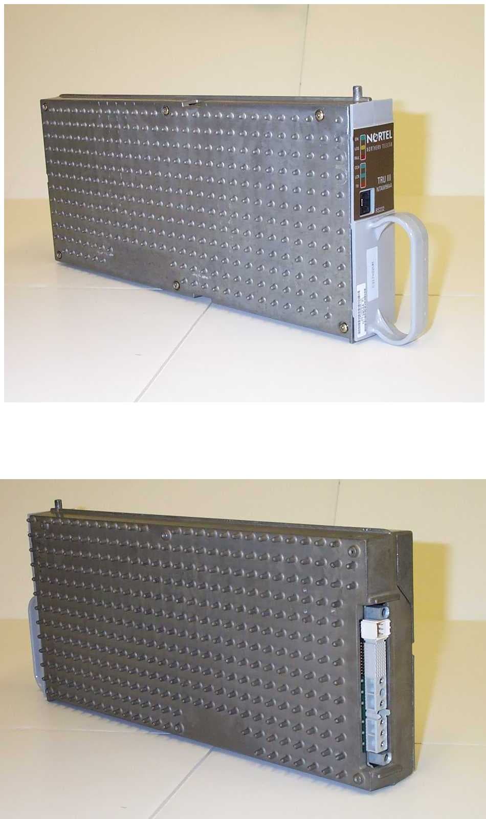
Click to zoom
Application Details
- Equipment Class
- PCB - PCS Licensed Transmitter
- Date of Grant
- Nov 23, 1999
- Application Purpose
- Original Equipment
- Date of Application
- Jul 28, 1999
- Frequency Range
- 1930.00000000 - 1990.00000000
- Company
- Avaya Canada Corporation
- Country
- Canada
Documents & Files
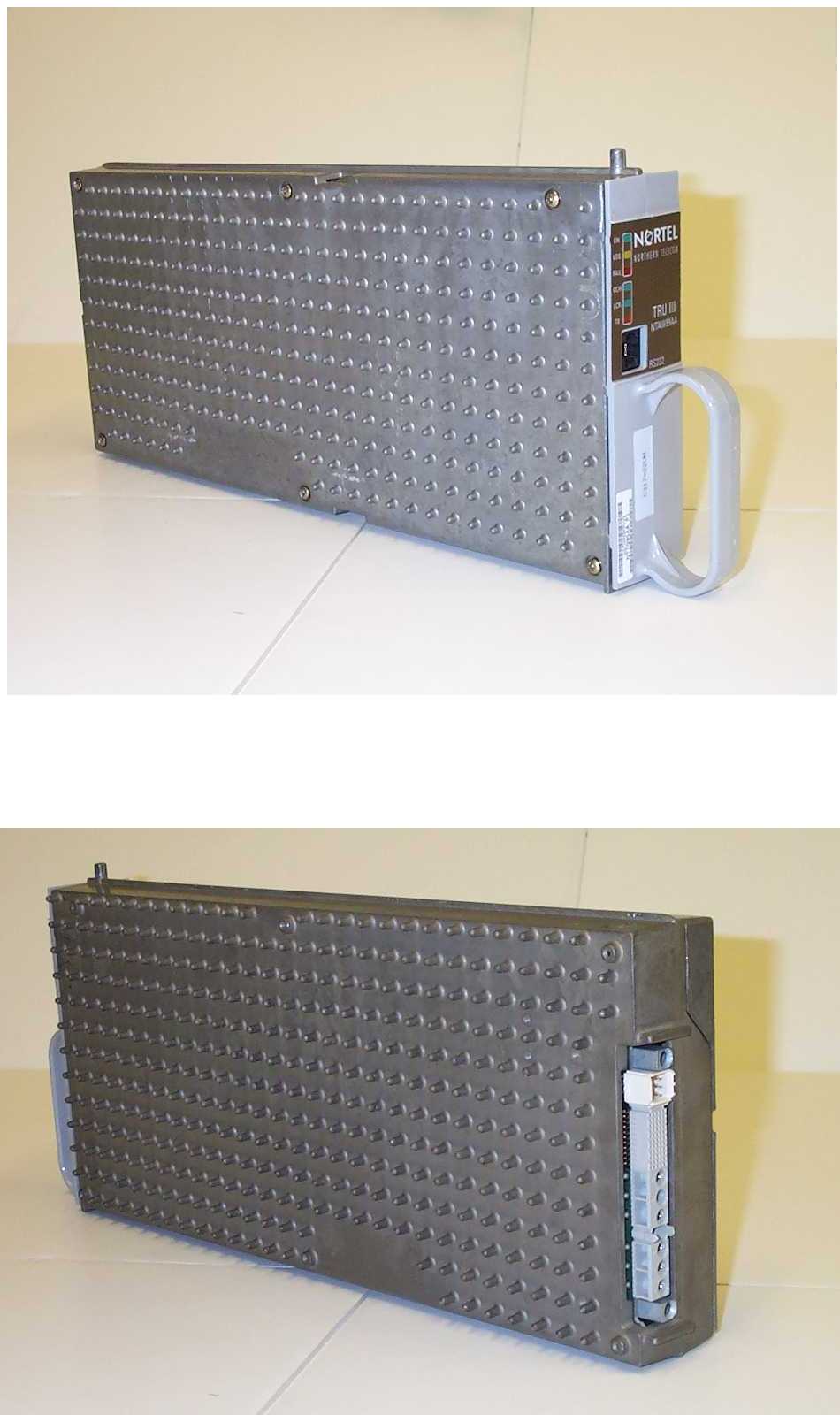
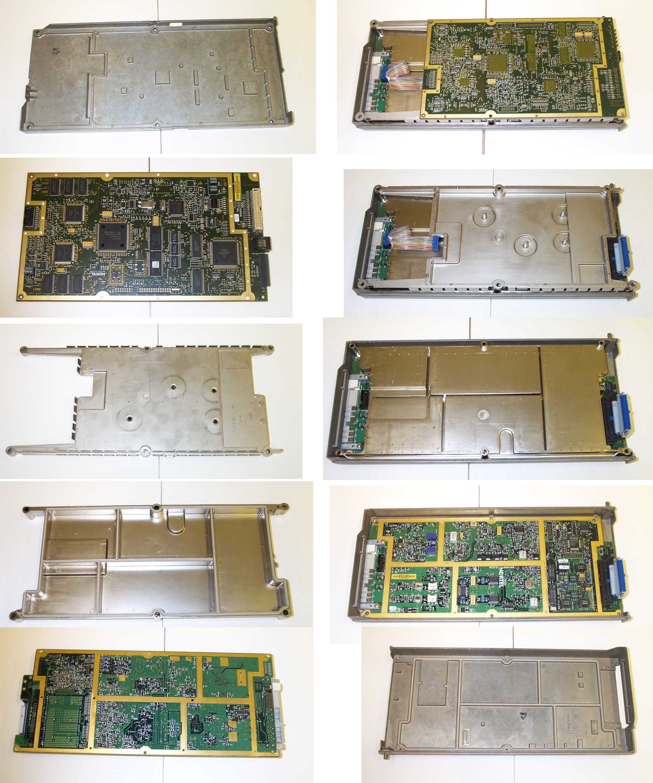
Document Text
Text extracted from the exhibit documents filed with the FCC. Open a document above to read the original.
Attestation Statements
July 30, 1999 Federal Communications Commission Authorization and Evaluation Division Equipment Authorization Branch 7435 Oakland Mills Road Columbia, Maryland, 21046 re: TRU3-1900 Transceiver(FCC ID: AB6NTTG90AA) Dear Sir, Madam, The TRU3-1900 has been investigated and found to comply with requirements found in IEEE C95.1-1991, “IEEE Standards for Safety Levels with Respect to Human Exposure to Radio Frequency Electromagnetic Fields, 3 kHz to 300 GHz” using methods specified in IEEE C95.3-1991, “Recommended Practice for the Measurement of Potentially Hazardous Electro- magnetic Fields, RF and Microwave.” The evaluation report is being kept on file at, Sincerely, Denis Lalonde Radio Compatibility Engineer Nortel Networks PO Box 3511 Station C Ottawa ON Canada K1Y 4H7 Canada
Cover Letter(s)
July 29, 1999 Federal Communications Commission Authorization and Evaluation Division Equipment Authorization Branch 7435 Oakland Mills Road Columbia, Maryland, 21046 re: TRU3-1900 Transceiver(FCC ID: AB6NTTG90AA) Dear Sir, Madam, Enclosed is a FCC Part 24 Type Acceptance application for the TRU3-1900 Transceiver. The FCC identifier is FCC ID:AB6NTTG90AA. The rated RF output power is 0.355 Watts. Nortel requests, pursuant to 47 CFR 0.459 of the commission’s rules, that the following items be held CONFIDENTIAL due to their proprietary nature. We consider this leading edge technology developed by Nortel and our partners and being new technology, would not want to make this information available to our competitors. 1. Technical Description 2. Block Diagram 3. Circuit Schematics If there is anything I can do to assist with the application, please do not hesitate to call me at (613) 763-7847. Sincerely, Denis Lalonde Radio Compatibility Engineer Nortel Networks PO Box 3511 Station C Ottawa ON Canada K1Y 4H7 Canada
ID Label/Location Info
Application for CertificationDoc: RF-00046-99 FCC ID:AB6NTTG90AAIssue: 1.0 Date: July 30, 1999Page 1 of 1 This document contains Proprietary and Confidential Information of Northern Telecom, Inc. FCC ID: AB6NTTG90AA CANADA: 332331XXXA Made in Canada Model No.: NTTG90AA
ID Label/Location Info
Location of FCC Label
Test Report
Application for CertificationDoc: RF-00046-99 FCC ID:AB6NTTG90AAIssue: 1.0 Date: July 30, 1999Page 1 of 22 This document contains Proprietary and Confidential Information of Northern Telecom, Inc. Introduction The following information is submitted for the Certification of the TRU3-1900 Transceiver by Northern Telecom, Inc., in accordance with Part 24, Subpart E and Part 2, subpart J of the FCC Rules and Regulations. The measurement procedures were in accordance with the requirements of Part 2. 2.1033(c)(1)Name of Applicant Applicant:Nortel Networks Corp.Ltd. Northern Telecom, Inc. 2305 Mission College Blvd. Santa Clara, CA 95054 Manufacturer:Nortel Networks Corp. Ltd. Northern Telecom Canada Limited 5111 Th. Street NE Calgary, Alberta, CANADA T5J 3G1 2.1033(c)(2) Equipment Identification Model No:NTTG90AA Trade Name:TRU3-1900 FCC ID:AB6NTTG90AA The TRU3-1900 will be produced in quantity. 2.1033(c)(3) Installation and Operating Instructions See the User Manual attachment 2.1033(c)(4) Types of Emissions The TRU3-1900 Transceiver is designed to operate in digital mode. The emission type designator is 30K0DXW. 2.1033(c)(5) Frequency Range The 1900 MHz TDMA Base Station will operate in the 1850 to 1990 MHz band, using 1930-1990 MHz for the transmitter and 1850 - 1910 MHz for the receiver. The channel bandwidth is 30 kHz. The channel separation is 30 kHz. For the base transmit channel frequency, the following formula is used: 0.030N + 1930.02 1N1999 ≥≤ Doc: RF-00046-99Application for Certification Issue: 1.0FCC ID:AB6NTTG90AA Page 2 of 22Date: July 30, 1999 This document contains Proprietary and Confidential Information of Northern Telecom, Inc. TRU channels 1 and 1999 are prohibited from use in the MTX software. The customer will not be able to successfully datafill and use either channel 1 or channel 1999 in their network, and therefore, neither channel will ever be activated in a customer network. 2.1033(c)(6) Operating Power The transmit power can be set to levels covering the range from -3 dBm to 25.5 dBm. 2.1033(c)(7) Maximum Power Rating The maximum RF power output is 25.5 dBm (0.355 W). 2.1033(c)(8) DC Power Consumption for RF Tx The DC current consumption of the RF module in the Transmit Receive Unit (TRU) is: 5 Vdctyp. 0.90 Amax.1.5 A -5 Vdctyp.0.31 Amax.0.6 A 10 Vdctyp.0.64 Amax.1.0 A 2.1033(c)(9) Tune-up Procedure A set of tests are performed during the production process to insure the product meets the specifications. A similar set of tests are also performed during the installation phase of the product in the field. A subset of the tests include: •Channel numbering and frequency check •Residual Modulation Check •Modulation Accuracy •RF output power and power stepping checks Frequency BlockTransmit Frequency Range (MHz)Receiver Frequency Range (MHz) A1930 - 19451850 - 1865 B1950 - 19651870 - 1885 C1975 - 19901895 - 1910 D1945 - 19501865 - 1870 E1965 - 19701885 - 1890 F1970 - 19751890 - 1895 Application for CertificationDoc: RF-00046-99 FCC ID:AB6NTTG90AAIssue: 1.0 Date: July 30, 1999Page 3 of 22 This document contains Proprietary and Confidential Information of Northern Telecom, Inc. 2.1033(c)(10) RF Circuits Description Circuit schematics of the TRU3-1900 Transceiver are attached to this application. Frequency Determining and Stabilizing All RF frequencies are derived from the Very Stable Master Oscillator (VSMO) which is external to the TRU3-1900. The VSMO provides eight accurate 4.8 MHz reference signal to the TRU3-1900. It contains two Oven Controlled Digital Voltage Controlled Crystal Oscillators (OCDCXO). Failure of an active oscillator automatically causes a switch-over to the standby unit with an oscillator alarm indication. The VSMO has a frequency stability better than 0.1 ppm. Spurious Radiation Suppression Spurious radiation is suppressed through proper shielding techniques of the TRU3-1900 main boards and via frequency selective combining and isolating equipment between the TRU3-1900 and the antenna. The transmit signal path always contains a frequency selective duplexer which typically provide an additional 30 dB rejection/isolation outside its passband. Unless otherwise noted, all measurements contained in this report were made at the TRU3-1900 output. Modulation Limiting Modulation limiting is performed by a digital device which is responsible for modulating the I and Q into an IF carrier. The modulated RF signal is filtered to remove any high frequency components before it is fed to the PA. 2.1033(c)(11) Equipment Identification Label A drawing and placement location of the equipment identification label is attached to this application. 2.1033(c)(12) Product Photographs Product photographs are attached to this application. 2.1033(c)(13) Digital Modulation The modulation used is Pi/4 DQPSK. 2.1033(c)(14) Measurement Results The measurement data required by FCC Part 2 sections 2.1046 through 2.1057, inclusive, measured in accordance with the procedures set out in section 2.1031 can be found in the following sections of this report.. An attestation confirming compli- ance with IEEE C95.1-1991 is also attached to this application. Doc: RF-00046-99Application for Certification Issue: 1.0FCC ID:AB6NTTG90AA Page 4 of 22Date: July 30, 1999 This document contains Proprietary and Confidential Information of Northern Telecom, Inc. Measurement Results Summary Table 1 is a summary of the measurement results for the TRU3-1900. Declaration of the Accuracy of Data The undersigned attest to the accuracy of the measurement data contained in this document. Denis LalondeStephen Cassidy Radio Compatibility EngineerRadio Compatibility Engineer Nortel NetworksNortel Networks Table 1: Measurement Results Summary FCC Measurement Specification FCC Limit Specification DescriptionResult 2.104624.232RF Power OutputPower (max) =25.4 dBm 2.1047Modulation CharacteristicsNA 2.1049Occupied BandwidthOBW (max) = 27.7 kHz 2.1051, 2.105724.238Spurious Emissions at Antenna Terminals Minimum of 32 dB m…
Text truncated - open the document above for the full version.
Contact Information
Applicant
Gwendolyn Faino(Legal Director)
Technical Contact
Northern TelecomDenis S Lalonde
[email protected]613 763-7847
Po Box: 3511, Station C · Ottawa, Ontario · Canada
Technical Specifications
| # | Rule Parts | Frequency Range | Power Output | Emission | Tolerance |
|---|---|---|---|---|---|
| 1 | 24E | 1.93 GHz - 1.99 GHz | 355.00 mW | 30K0DXW | 0.0300000000 ppm |
Other Applications from Avaya Canada Corporation

AB6NT2100V3231
Mar 30, 2008AWS Radio
Equipment Class
TNB - Licensed Non-Broadcast Station Transmitter
AB6BTS9000
Dec 19, 2007Base Transceiver Station
Equipment Class
PCB - PCS Licensed Transmitter
AB6NT2100MFRM3
Oct 10, 2007NT2100 MFR M3 AWS radio
Equipment Class
TNB - Licensed Non-Broadcast Station Transmitter
AB6NTQ220AB
Jun 12, 2007NTQ220ABE5 Radio Module
Equipment Class
TNB - Licensed Non-Broadcast Station Transmitter
AB6BTS6000D
Jun 07, 2007GSM 6000 Base Transceiver Station
Equipment Class
PCB - PCS Licensed Transmitter