AB6UMTS1900MONOUMTS 1900 Mono iBTS
Avaya Canada Corporation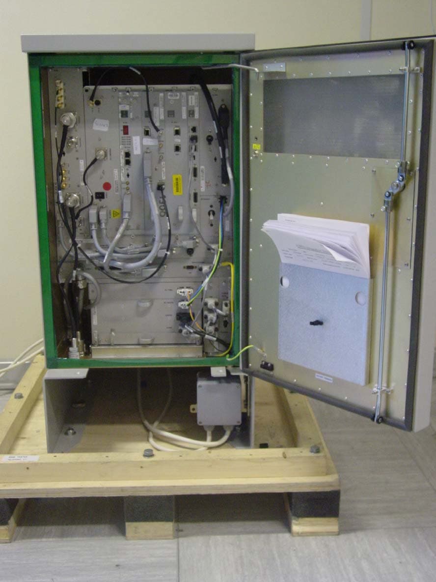
Click to zoom
Application Details
- Equipment Class
- PCB - PCS Licensed Transmitter
- Date of Grant
- Oct 01, 2003
- Application Purpose
- Original Equipment
- Date of Application
- Oct 01, 2003
- Equipment Note
- UMTS 1900 Mono iBTS
- Frequency Range
- 1932.40000000 - 1987.60000000
- Company
- Avaya Canada Corporation
- Country
- Canada
Documents & Files
Document Text
Text extracted from the exhibit documents filed with the FCC. Open a document above to read the original.
Users Manual
UMT/DCL/DD/0002 411–8111–905 Wireless Service Provider Solutions UMTSProduct FundamentalsAbout the Univity iBTSUMT/DCL/DD/0002 03.08/EN Draft September 2003411–8111–905 Wireless Service Provider SolutionsUMTSProduct FundamentalsAbout the Univity iBTSDocument number: UMT/DCL/DD/0002 411–8111–905 Document issue: 03.08/EN Document status: Draft Product release: UMTS03 Date: September 2003 Copyright © 2000-2003 Nortel Networks , All Rights ReservedPrinted in France NORTEL NETWORKS CONFIDENTIAL The information contained herein is the property of Nortel Networks and is strictly confidential. Except asexpressly authorized in writing by Nortel Networks, the holder shall keep all information contained hereinconfidential, shall disclose the information only to its employees with a need to know, and shall protect theinformation, in whole or in part, from disclosure and dissemination to third parties with the same degree ofcare it uses to protect its own confidential information, but with no less than reasonable care. Except asexpressly authorized in writing by Nortel Networks, the holder is granted no rights to use the informationcontained herein.Information is subject to change without notice. Nortel Networks reserves the right to make changes in design or components asprogress in engineering and manufacturing may warrant.Nortel Networks, the Nortel Networks logo, the Globemark, Univity iBTS, Univity RNC, Passport, and Unified Networks aretrademarks of Nortel Networks. Bussmann is a trademark of Bussmann. All other brand and product names are trademarks orregistered trademarks of their respective holders. PUBLICATION HISTORY SYSTEM RELEASE UMTS03September 2003 Issue 03.08/EN DraftUpdate for OAM V3.1/RAN V3.1 Customer ReadinessIntroduction of UMTS 1900 Univity iBTSs Mono and Indoor Compact August 2003 Issue 03.07/EN PreliminaryUpdate after internal review July 2003 Issue 03.06/EN DraftUpdate for OAM V3.1/RAN V3.1 Customer ReadinessIntroduction of UMTS 1900 iBTSs Indoor 2 and Outdoor July 2003 Issue 03.05/EN PreliminaryUpdate after FCC Regulatory information validation June 2003 Issue 03.04/EN DraftFCC Regulatory Information enhancement: addition of North-American rules May 2003 Issue 03.03/EN PreliminaryUpdate after Internal Review April 2003 Issue 03.02/EN DraftUpdate for OAM V3.1/RAN V3.1 April 2003 Issue 03.01/EN StandardMinor updateDocument version change (UTRAN V2.1 belong to UMTS V3.0b system release) SYSTEM RELEASE UMTS02January 2003 Nortel Networks Confidential Publication history i Copyright © 2000-2003 Nortel Networks About the Univity iBTS Issue 02.08/EN StandardEditorial Update to introduce the iBTS Indoor 2 November 2002 Issue 02.07/EN StandardUpdate for UMTS V2.1 UTRAN September 2002 Issue 02.06/EN PreliminaryUpdate for UMTS V2.0d UTRAN July 2002 Issue 02.05/EN PreliminaryMinor update July 2002 Issue 02.04/EN PreliminaryUpdate after internal review June 2002 Issue 02.03/EN DraftUpdate for UMTS V2.0c UTRAN May 2002 Issue 02.02/EN PreliminaryUpdate after internal review March 2002 Issue 02.01/EN Draft• introduction of the STSR2 configuration • introduction of the new iBTS Street • drop and insert feature description SYSTEM RELEASE UMTS01February 2002 Issue 01.08/EN PreliminaryUpdate after review January 2002 Issue 01.07/EN DraftUpdate according the product release change. Nortel Networks Confidential Publication history ii UMT/DCL/DD/0002 03.08/EN Draft September 2003 Copyright © 2000-2003 Nortel Networks 411–8111–905 October 2001 Issue 01.06/EN PreliminaryUpdate after review September 2001 Issue 01.05/EN DraftThe following changes were made throughout the document:• modify modules organization throughout the document • update the iBTS features according to the system release change • update the configuration rules • add the TMA description • update the PFM description • update the ac plinth description • update the batteries description • modify software section July 2001 Issue 01.04/EN PreliminaryUpdate after review June 2001 Issue 01.03/EN DraftThe following changes were made throughout the document:• update the iBTS description and configuration according to the system release • update the hardware description • add information about physical interfaces, cabling, functional architecture, andsoftware • add and update the ancillary modules • add the configuration description • delete the dimensioning section January 2001 Issue 01.02/EN PreliminaryUpdate after review December 2000 Issue 01.01/EN DraftCreation Nortel Networks Confidential Publication history iii Copyright © 2000-2003 Nortel Networks About the Univity iBTS About this publication 1 What is in new about the Univity iBTS 3 Univity iBTS regulatory information 4 UTRAN introduction of the UMTS03 solution 9 Univity iBTS basic characteristics 13 Univity iBTS introduction 14 Univity iBTS key features 23 Univity iBTS mechanical characteristics 24 Univity iBTS architecture and configuration 30 Univity iBTS architecture 31 Univity iBTS RF configuration 35 Univity iBTS interfaces 48 Uu interface physical description 49 Iub interface physical description 50 Univity iBTS hardware 51 Univity iBTS hardware presentation 52 Univity iBTS digital shelf 74 Univity iBTS digital shelf description 75 CEM (Channel Element Module) 82 iCEM (internet Channel Element Module) 89 CCM (Core Control Module) 94 iCCM (internet Core Control Module) 98 TRM (Transceiver Receiver Module) 103 iTRM (internet Transceiver Receiver Module) 112 GPSAM/cGPSAM (GPS and Alarm Module) 116 Univity iBTS RF block 120 Nortel Networks Confidential Table of contents iv UMT/DCL/DD/0002 03.08/EN Draft September 2003 Copyright © 2000-2003 Nortel Networks 411–8111–905 Univity iBTS Radio Frequency (RF) Description 121 MCPA (Multi Carrier Power Amplifier) 125 Tx Splitter 130 DDM (Dual Duplexer Module) 133 Univity iBTS cabinet other modules 139 MCA (Manufacturing, Commissioning, and Alarm) module 140 Mono Control Board 145 Single Power Control Module (SPCM) 147 TMA (Tower Masterhead …
Text truncated - open the document above for the full version.
External Photos
UMTS Mono iBTS pictures Figure 1: Front view, doors open Figure 2: Front view, doors closed Figure 3: Left side view Figure 4: Back side view Figure 5: Right side view
ID Label/Location Info
CSA/FCC MARK Reg u latory Lab el iBTS MONO (ref: P0606560) PCM Protection Label (ref: P0937414) 29-08-2003 EC: 103-11994 P0606560 1:1 0101 PD PD 11 CSA/FCC MARK Regulatory Label UMTS MONO iBTS This device complies with Part 15 of the FCC rules. Operation is subject to the following 2 conditions: (1) this device may not cause harmful interference, and (2) this device must accept any interference received, including interference that may cause undesired operation. This Class B digital apparatus meets all requirements of the Canadian interference causing equipment regulations. Cet appareil numérique de la classe B respecte toutes les exigences du règlement Canadien sur le matériel causant des interférences. FCC ID : AB6UMTS1900MONO :US AB6XDNANUMTSMONO Made in the U.S.A. Fabriqué aux E.U. Remove this section, replace with appropriate label below. Made in France Fabriqué en France COREL 10.0 07/02 NOTES: 1. UNLESS OTHERWISE SPECIFIED, ALL DIMENSIONS ARE EXPRESSED IN MILLIMETERS. TOLERANCES SHALL BE: 1 DECIMAL PLACE = + 0.5 2 DECIMAL PLACES = + 0.25 3 DECIMAL PLACES = + 0.125 ALL LABEL CORNERS SHALL HAVE A 0.75 RADIUS. 2. TO CONVERT MILLIMETERS TO INCHES: 25.40 MILLIMETERS = 1 INCH. 3. THIS DESIGN FILE WAS CREATED IN ACCORDANCE WITH NT STD 1517.20. LABEL/ARTWORKS MUST BE MANUFACTURED IN ACCORDANCE WITH NPS90942. 4. THE ARTWORK SHALL BE PLOTTED AT A MINIMUM OF 1200 DPI. THE TEXT FONT(S) SHALL BE: UNIVERS 67 CONDENSED BOLD PER NPS90942. TEXT ABOVE AND BELOW UL OR CSA SYMBOLS SHALL BE UNIVERS 57 CONDENSED PER NPS90942. 5. MATERIAL: 0.25 CLEAR POLYCARBONATE PER R0115902 FINISH: VELVET/MATTE ADHESIVE: 0.05 PRESSURE SENSITIVE WITH PEEL OFF LINER PER R0113138 6. COLOURS SHALL CONFORM TO NORTHERN TELECOM OBSERVATIONAL STANDARD 2701.01. BACKGROUND: BTS LIGHT GREY PER NORTHERN TELECOM STANDARD S-33470 TEXT AND GRAPHICS: NORTEL DARK GRAY PER NORTHERN TELECOM STANDARD S-33310 BACKGROUND AT TOP OF LABEL: NORTEL LIGHT GRAY PER NORTHERN TELECOM STANDARD S-33310 7. LABEL TO BE REVERSE SCREEN PRINTED PER NPS90942-2. KISS-CUT KISS-CUT 170,0 mm 80,0 mm 40,00 mm 40,00 mm 13,00 mm UMTS MONO iBTS NEMA 3R enclosure 13,00 mm Operation mode 1 AC supply only 208-240 Vac, 50-60Hz, 13A (L1+L2+GND) AC maximum voltage range: 187-264 Vac Or Operation mode 2 AC+DC supply 208-240Vac, 50-60Hz, 10A (L1+L2+GND) AC maximum voltage range : 187-264Vac -48V = 15A DC maximum voltage range : -40.5 to -57 Vdc NOTES: 1. UNLESS OTHERWISE SPECIFIED, ALL DIMENSIONS ARE EXPRESSED IN MILLIMETERS. TOLERANCE SHALL BE: 1 DECIMAL PLAVE = + 0.5 2 DECIMAL PLACES = + 0.25 3 DECIMAL PLACES = + 0.125 ALL LABEL CORNERS SHALL HAVE A .75 RADIUS. 2. TO CONVERT MILLIMETERS TO INCHES: 25.40 MILLIMETERS = 1 INCH 3. THIS DESIGN FILE WAS CREATED IN ACCORDANCE WITH NT STD 1517.20. LABEL/ARTWORKS MUST BE MANUFACTURED IN ACCORDANCE WITH NPS90942. 4. THE ARTWORK SHALL BE PLOTTED AT A MINIMUM OF 1200 DPI. THE TEXT FONT(S) SHALL BE: UNIVERS 67 CONDENSED BOLD PER NPS90942. 5. MATERIAL: 0.25 CLEAR POLYCARBONATE PER R0115902 FINISH: VELVET/MATTE ADHESIVE: 0.127 PRESSURE SENSITIVE WITH PEEL OFF LINER PER R0114911 6. COLOURS SHALL CONFORM TO NORTHERN TELECOM OBSERVATIONAL STANDARD 2701.01. BACKGROUND: WHITE PER NORTHERN TELECOM STANDARD S-33294 BACKGROUND BEHIND CAUTION SYMBOL AND CAUTION TEXT: CAUTION YELLOW PER NORTHERN TELECOM STANDARD S-33357 TEXT AND GRAPHICS: BLACK PER NORTHERN TELECOM STANDARD S-33154 7. LABEL TO BE REVERSE SCREEN PRINTED PER NPS90942-2. For Safety compliance to CSA/UL requirements the following must be respected : 02-07-2003 EC: 103-11850 P0937414 1:1 0101HP HP 11 PCM Protection label COREL 10.0 07/02 CAUTION 130,0 mm 32,0 mm 30,0 mm - For PCM regular wire connection to the telecommunication network, a CSA/UL Certified secondary protection module must be provided between the iBTS and the telecommunication network (for outdoor cabinet, the protection must be installed inside the iBTS). - For PCM wireless link, a CSA/UL Certified microwave module must be used with the iBTS.
Internal Photos
iTRM Module: Internal Pictures Figure 1: iTRM Logic Board Figure 2: iTRM Radio Board
Test Report
PUBLICATION HISTORY 16/Sept/2003 S. BALE Value error correction of the Mono Maximum Output Power on T channel in Table 2. Issue V01.02 / EN Standard 01/Sept/2003 S. BALE Document creation. Issue V01.01 / EN Standard Radio Test Report UMTS 1900 iBTS for the iModules according to FCC Part 24 UMT/BTS/DJD/008014 V01.02 / EN Standard 16/Sept/2003 Page 3/80 CONTENTS 1. INTRODUCTION ...................................................................................................................... 4 1.1. OBJECT.............................................................................................................................. 4 1.2. SCOPE OF THIS DOCUMENT................................................................................................... 4 1.3. AUDIENCE FOR THIS DOCUMENT............................................................................................ 4 2. RELATED DOCUMENTS ......................................................................................................... 4 2.1. APPLICABLE DOCUMENTS..................................................................................................... 4 2.2. REFERENCE DOCUMENTS..................................................................................................... 4 3. TEST RESULTS ....................................................................................................................... 5 3.1. INTRODUCTION............................................................................................................... 5 3.2. MEASUREMENT RESULTS.............................................................................................. 5 3.3. MAXIMUM OUTPUT POWER............................................................................................... 6 3.3.1 FCC REQUIREMENTS .............................................................................................. 6 3.3.2 Test results................................................................................................................. 6 3.3.3 Test procedure........................................................................................................... 7 3.4. OCCUPIED BANDWIDTH ................................................................................................. 8 3.4.1 FCC REQUIREMENTS .............................................................................................. 8 3.4.2 Test results................................................................................................................. 8 3.4.3 Test procedure......................................................................................................... 10 3.5. SPURIOUS EMISSIONS AT ANTENNA TERMINALS ...................................................... 11 3.5.1 Fcc requirements...................................................................................................... 11 3.5.2 Test results............................................................................................................... 12 3.5.3 Test procedure......................................................................................................... 73 3.6. CONCLUSION..................................................................................................................... 74 3.7. MEASUREMENT EQUIPMENT LIST......................................................................................... 75 4. TECHNICAL STATUS OF THE MODULES CONSTITUTING THE TESTED EQUIPMENT..... 76 5. ABBREVIATIONS AND DEFINITIONS................................................................................... 79 5.1. ABBREVIATIONS................................................................................................................. 79 5.2. DEFINITIONS...................................................................................................................... 80 Radio Test Report UMTS 1900 iBTS for the iModules according to FCC Part 24 UMT/BTS/DJD/008014 V01.02 / EN Standard 16/Sept/2003 Page 4/80 1. INTRODUCTION 1.1. OBJECT This document presents the measurement results of tests performed on Nortel Networks UMTS iBTS according to FCC specifications. 1.2. SCOPE OF THIS DOCUMENT This document applies to Nortel FDD UMTS Indoor 2 iBTS UMTS Outdoor iBTS UMTS Mono iBTS 1.3. AUDIENCE FOR THIS DOCUMENT This document is to be used by any person needing a view on Nortel FDD UMTS 1900 iBTS. 2. RELATED DOCUMENTS 2.1. APPLICABLE DOCUMENTS [A1] UMT/BTS/APP/0022 Methodology of UMTS BTS validation under 25.141 specifications [A2] UMT/BTS/DD/0017 e-mobility iBTS platform/UMTS/GSM product specification [A3] UMT/BTS/DPL/07135 1900 MHz UMTS Project Qualification Plan [A4] UMT/BTS/DPL/7917 Radio Test Plan for the qualification of the 1900 iBTS with iModules 2.2. REFERENCE DOCUMENTS [R1] 47CFR Part 24 PERSONAL COMMUNICATIONS SERVICES January 2001 [R2] 47CFR Part 2 FREQUENCY ALLOCATIONS AND RADIO TREATY MATTERS; GENERAL RULES AND REGULATIONS October 2001 Radio Test Report UMTS 1900 iBTS for the iModules according to FCC Part 24 UMT/BTS/DJD/008014 V01.02 / EN Standard 16/Sept/2003 Page 5/80 3. TEST RESULTS 3.1. INTRODUCTION This document presents the RF tests performed for the qualification of the 1900 iBTS with iModules. UMTS Indoor2 iBTS is feeded with -48V DC as standard configuration. As an option, UMTS Indoor2 may be feeded with +24V DC, through an additional DC to DC converter (+24 V to -55 V). UMTS Outdoor iBTS is feeded with 220V AC split phase. UMTS Mono iBTS is feeded with -48V DC. The following information is submitted to introduce a Certification of the UMTS 1900 iBTS for Northern Telecom, Inc: - According to 47CFR Part 24, Subpart E - According to 47CFR Part 2, Subpart J of the FCC Rules and Regulations. The measurement procedures were in accordance with the requirements of Part 2.947. 3.2. MEASUREMENT RESULTS Table 1 is a summary of the measurement results performed in this report. Description & Configuration code Measureme…
Text truncated - open the document above for the full version.
Test Report
Radio Tests Report in Extreme Environment for 1900 MHz UMTS Mono iBTS equipped with i- modules This confidential document is the property of SANMINA-SCI, it must not be copied or circulated except in its entirety form. A SANMINA-SCI formal written agreement is required for any partial copy of this document. RPT-T-030525-6G1 A Approved 30/09/03 Page 2/14 PUBLICATION HISTORY VERSION DATE AUTHOR MODIFICATION A 30/09/2003 J. PALARD Creation of the document Radio Tests Report in Extreme Environment for 1900 MHz UMTS Mono iBTS equipped with i- modules This confidential document is the property of SANMINA-SCI, it must not be copied or circulated except in its entirety form. A SANMINA-SCI formal written agreement is required for any partial copy of this document. RPT-T-030525-6G1 A Approved 30/09/03 Page 3/14 CONTENTS 1. INTRODUCTION..................................................................................................................4 2. RELATED DOCUMENTS.....................................................................................................4 2.1. APPLICABLES DOCUMENTS......................................................................................4 2.2. REFERENCE DOCUMENTS.........................................................................................4 3. IDENTIFICATION OF TESTED TECHNICAL VARIANT AND OF THE MODULES CONSTITUTING THE TESTED EQUIPMENT...........................................................................................................5 4. SYNTHESIS OF TESTS RESULTS FOR ALL VARIANTS.....................................................6 5. TESTS DATES AND OPERATORS FOR EACH VARIANT....................................................6 6. TESTS APPARATUS USED FOR TESTS.............................................................................6 7. TESTS RESULTS OF 3GPP TS 25.141 STANDARD.............................................................7 7.1. BASE STATION MAXIMUM OUTPUT POWER AT 30W (CL. 6.2.1)................................7 7.2. FREQUENCY ERROR AT PMAX-3DB (CL. 6.3)............................................................8 7.3. FREQUENCY ERROR AT PMAX-18DB (CL. 6.3)..........................................................9 7.4. REFERENCE SENSITIVITY LEVEL (CL. 7.2)..............................................................10 8. TESTS RESULTS OF 47 CFR PART 24.............................................................................11 9. CONCLUSION...................................................................................................................13 10. ABBREVIATIONS & DEFINITIONS....................................................................................14 10.1. ABBREVIATIONS......................................................................................................14 10.2. DEFINITIONS.............................................................................................................14 Radio Tests Report in Extreme Environment for 1900 MHz UMTS Mono iBTS equipped with i- modules This confidential document is the property of SANMINA-SCI, it must not be copied or circulated except in its entirety form. A SANMINA- SCI formal written agreement is required for any partial copy of this document. RPT-T-030525-6G1 A Approved 30/09/03 Page 4/14 1. INTRODUCTION This document presents the measurements results of Radio tests performed on the 1900 MHz UMTS Mono iBTS equipped with UMTS 1900 MHz i-modules, in extreme environment according to 3GPP TS 25.141 and 47CFR Part 24 and Nortel requests. The measurements reported in this document have been performed in Sanmina-SCI climatic chamber. The tests definitions, methods and requirements follow the applicable version of the 3GPP TS 25.141 and 47CFR Part 24 as defined in the PLN-T-030466-6G1 Test Plan. The tests results in this report relate to the equipment under test only described below and in the Nortel Networks AVL ref: UMT/BTS/DJD/7225 Ver 01.01/EN: Product: UMTS Mono iBTS Manufacturer: Nortel Networks Type: UMTS 1900 Configuration: OTOR1 Power supply: DC: -48Vdc and AC: 208-240Vac for Heater (See Note below) Power supply range: DC Range: -40.5Vdc to –57Vdc Extreme temperature range: -20°C to +45°C Note: The UMTS Mono iBTS has two Operation Mode: Mode 1: AC Supply Only (208-240Vac) Mode 2: AC +DC Supply (AC for Heater: 208-240VAC and DC: -48Vdc) As the Mode 1 has been used during the RF tests performed on the UMTS Mono iBTS with Alpha modules, the Mode 2 has been chosen to performed the RF tests on the UMTS Mono iBTS with i-modules. This document is addressed to Nortel Networks and Sanmina-SCI R&D department involved in the development of the UMTS Mono iBTS and UMTS 1900 MHz i-modules. 2. RELATED DOCUMENTS 2.1. APPLICABLES DOCUMENTS [A1] 3GPP TS 25.141 3 rd generation partnership project: Technical Specification Group Radio Access Networks; Base Station (BS) conformance testing (FDD) Release 1999; Version 3.12.0 [A2] 47 CFR Part 24 Personal Communications Services 2.2. REFERENCE DOCUMENTS [R1] UMT/BTS/DPL/07135 1900 MHz UMTS Project Qualification Plan [R2] PLN-V-030355-6G1 1900 Mhz UMTS PI Qualification Plan [R3] UMT/BTS/DD/453 Mechanical, Environmental and Electrical Requirement Specification for a Mono iBTS Cabled Cabinet [R4] Nortel-sinf-00358 Mono iBTS Cooling Unit Description [R5] UMT/BTS/DJD/7225 Hardware Delivery form for 1900 MHz UMTS Mono iBTS [R6] PLN-T-030465-6G1 Radio Tests Plan in Extreme Environment for UMTS Mono iBTS equipped with 1900 MHz i-modules Radio Tests Report in Extreme Environment for 1900 MHz UMTS Mono iBTS equipped with i- modules This confidential document is the property of SANMINA-SCI, it must not be copied or circulated except in its entirety form. A SANMINA-SCI formal written agreement is required for any partial copy of this document. RPT-T-030525-6G1 A Approved 30/09/03 Page 5/14 3. IDENTIFICATION OF TESTED TECHNICAL VARIANT AND OF THE MODULES CONSTITUTING THE TESTED EQUIPMENT Tests were performed on all…
Text truncated - open the document above for the full version.
Contact Information
Applicant
Gwendolyn Faino(Legal Director)
Technical Contact
Nortel NetworksLuc Moulin
[email protected]+33139445609
Parc d'activit� de Magny-Chateaufort · Yvelines Cedex 9 · France
Test Firm
EMITECH ANGERSOlivier ROY
Technical Specifications
| # | Rule Parts | Frequency Range | Power Output | Emission | Tolerance |
|---|---|---|---|---|---|
| 1 | 24E | 1.93 GHz - 1.99 GHz | 24.83 W | 4M60F9W | 90.0000000000 Hz |
Other Applications from Avaya Canada Corporation

AB6NT2100V3231
Mar 30, 2008AWS Radio
Equipment Class
TNB - Licensed Non-Broadcast Station Transmitter
AB6BTS9000
Dec 19, 2007Base Transceiver Station
Equipment Class
PCB - PCS Licensed Transmitter
AB6NT2100MFRM3
Oct 10, 2007NT2100 MFR M3 AWS radio
Equipment Class
TNB - Licensed Non-Broadcast Station Transmitter
AB6NTQ220AB
Jun 12, 2007NTQ220ABE5 Radio Module
Equipment Class
TNB - Licensed Non-Broadcast Station Transmitter
AB6BTS6000D
Jun 07, 2007GSM 6000 Base Transceiver Station
Equipment Class
PCB - PCS Licensed Transmitter