ABZ89FC3789Altair WHiSP
Motorola Solutions, Inc.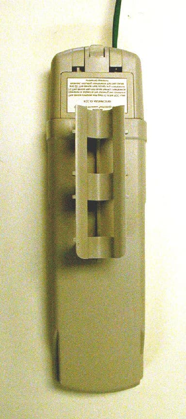
Click to zoom
Application Details
- Equipment Class
- NII - Unlicensed National Information Infrastructure TX
- Date of Grant
- Sep 06, 2001
- Application Purpose
- Original Equipment
- Date of Application
- Sep 06, 2001
- Equipment Note
- Altair WHiSP
- Frequency Range
- 5275.00000000 - 5325.00000000
- Company
- Motorola Solutions, Inc.
- Country
- United States
Documents & Files
Document Text
Text extracted from the exhibit documents filed with the FCC. Open a document above to read the original.
Users Manual
D R A F T – 9/10/2001 Getting Started with Motorola WHiSP SM D R A F T – 9/10/2001 Warranty Information Motorola offers a warranty covering a period of one (1) year from the date of purchase by the retail customer. If a product is found defective during the warranty period, Motorola will repair or replace the product with the same or a similar model, which may be a reconditioned unit, without charge for parts or labor. D R A F T – 9/10/2001 1. Congratulations! You have purchased a Motorola WHiSP radio, the latest innovation in high speed wireless networking. The Motorola WHiSP radio lets you easily network at high speeds with no wiring. - Network speeds of 10baseT. - Small compact design - No special set up on your PC. 2. Getting to Know your Radio. - The base cover snaps off the gain access to connectors and LED’s. Ethernet Cable WHiSP SM RJ45 Connector Connection LEDs Base Cover D R A F T – 9/10/2001 Installing WHiSP Mount your WHiSP radio in a location where it is facing the transmitting tower - Plug the power adapter’s Ethernet patch into your PC Ethernet port. - Connect an Ethernet cable between the other side of the power adapter Ethernet patch and the RJ45 socket on the WHiSP SM. - See the section on “Aligning your WHiSP” in the trouble shooting section of this manual to insure best performance. - IMPORTANT NOTE: To comply with FCC RF exposure compliance requirements, the following antenna installation and device operating configurations must be satisfied. The antenna used for this transmitter must be installed to provide a separation distance of at least 20cm from all persons and must not be co-located or operating in conjunction with any other antenna or transmitter. Installers and end- users must be provided with antenna installation instructions and transmitter operating conditions for satisfying RF exposure compliance. D R A F T – 9/10/2001 Configuring your computer Your PC will not require any special setup beyond proper installation of Ethernet drives & drivers. Configuration of your computer’s TCP/IP parameters will be specified by your ISP. However, you will need to temporarily configure your computer’s TCP/IP parameters in order to configure your WHiSP radio. Configuring your Windows 98 computer These instructions are for Windows98 and presume you have already installed your Ethernet card or Network Interface Card (NIC), and have installed TCP/IP protocols. If these are not yet installed, they must be installed before proceeding. To temporarily reconfigure your TCP/IP protocol to configure your WHiSP radio, first begin by RIGHT clicking on the Network Neighborhood icon on your desktop. A side menu appears, and you must LEFT click on the bottom item labeled “Properties”. Presuming your Network Interface Card (NIC) or Ethernet card is already installed along with the TCP/IP protocol, you will see both under the list of network components installed. Click the TCP/IP protocol item in the component list to highlight it, and then click on the “Properties” button. This will bring up the TCP/IP Properties screen shown next. D R A F T – 9/10/2001 In order to configure your WHiSP radio, you must temporarily assign a fixed IP address to your computer. Click the radial “Specify an IP address” so that a dot appears. Then you may enter a temporary IP address and subnet mask. Enter the IP address 192.168.100.4, and subnet mask 255.255.255.0. You may then click OK, and OK again to the Network Properties dialog. Your computer will copy some Windows install files, and may ask for the Windows CD if Windows install files (called CAB files) were not copied to your hard drive at installation time. Your computer will typically indicate that it needs to reboot before the settings take effect. You will need to reboot before proceeding to configure your WHiSP radio. After configuring and alignment of your WHiSP radio, follow the service provider instructions for returning your TCP/IP properties to “Obtain an IP address automatically” or other “specific IP address” assigned value as instructed. Expect your system to reinstall files (or ask for the Windows CD if CAB files are not copied on your hard drive) and request reboot each time TCP/IP parameters are changed. You may return your TCP/IP parameters to the specific temporary IP address at any time to review or reconfigure your WHiSP radio. D R A F T – 9/10/2001 Configuring your Windows 2000 computer To temporarily reconfigure your TCP/IP protocol to configure your WHiSP radio, first begin by RIGHT clicking on the Network Neighborhood icon on your desktop. A side menu appears, and you must LEFT click on the bottom item labeled “Properties”. When you click properties a new window will come up, it will look something like this. When this window comes up, RIGHT click on the icon labeled Local Area Connection. Once again LEFT click the properties button that is on the very bottom of the box. Presuming your Network Interface Card (NIC) or Ethernet card is already installed along with the TCP/IP protocol, you will see the card listed under the “Connect using” field, and the Internet Protocol (TCP/IP) under the list of components used by this connection. Click the TCP/IP protocol item in the component list to highlight it, and then click on the “Properties” button. This will bring up the TCP/IP Properties screen shown next. D R A F T – 9/10/2001 In order to configure your WHiSP radio, you must temporarily assign a fixed IP address to your computer. Click the radial “Use the following IP address” so that a dot appears. Then you may enter a temporary IP address and subnet mask. Enter the IP address 192.168.100.4, and subnet mask 255.255.255.0. Once you have entered the IP address and subnet mask, you may click the OK button, since you are using Windows 2000 you will not need to restart your computer. After configuring and alignment of your WHiSP radio, follow the service provider instructions for returning your TCP/IP properties to “Obtain an IP address a…
Text truncated - open the document above for the full version.
Cover Letter(s)
FCC ID: ABZ89FC3789 Request for Confidentiality In accordance with 47 C.F.R. Section 0.459, we, Motorola Inc., hereby request confidentiality for the block diagram, schematic and product description presented for certification. In support of the Request for Confidentiality, the following is stated: Enclosed within this application is technical information which we deem to be trade secrets and proprietary. If made public, the information might be used to our disadvantage. To assist in assuring that we receive the full value of our product and protect its competitive posture, we respectfully request this grant of confidentiality. Motorola Inc.
RF Exposure Info
Motorola FCC ID: ABZ89FC3789 The Motorola Whisp device requesting certification is exluded from RF exposure because it is a fixed transmitter mounted on outdoor permanent structures and satisfys the MPE requirements of 2.1091 because of its low power.
Test Report
Discussion with Technical Contact at Motorola to Resolve Technical Issues 09/07/2001Telecon with Motorola Inc: Gary Schulz; Rich Keniuk; John Ley Elite Electronic Engineering Inc.: Ray Klouda Tuning Range of Device- Device can tune from 5275 to 5325 MHz in 5 MHz steps. Power output is 30 dBm ERP. The patch antenna is integrated in the PC board. No other antennas are used with this device. Testing at minimum of 3 frequency required- Device was checked at all channels. Worst-case results were reported. Band edge compliance tests: At high end: The power spectral density plot shows the highest channel. Emissions in the restricted band 5.35 to 5.46 MHz were checked worst case was reported. The worst case was 3.8 dB below limit. See page 2 of report. At low end: Use the power spectral density plot at the highest channel, which has the identical emission characteristics as the lowest channel to demonstrate emissions in the 5.15 to 5.25 GHz band will comply to 15.407(2) and (7). The plot shows that the emissions have maximum ERP of –45 dBm/MHz. Technical Description of how 15.407(c) is met: The logic in the radio inhibits transmission in the event of frequency error. The data protocol and firmware prevent transmission when there is no data present. Frequency Stability: This device is specified to operated over the temperature range of – 30 deg. C to +65 deg. C with frequency tolerance of 25 ppm. Operational Manual shows Upper Band frequency range? This device does not include the upper band. The upper band will be a separate device.
Contact Information
Applicant
Matthew Nawrocki
Technical Contact
Motorola Broadband Wireless Technology CenterGary Schulz
847-538-5252
50 E. Commerce Drive · Schaumburg, Illinois · United States
Test Firm
DLS Electronic Systems, Inc.William Stumpf
Technical Specifications
| # | Rule Parts | Frequency Range | Power Output | Tolerance |
|---|---|---|---|---|
| 1 | 15E | 5.28 GHz - 5.33 GHz | 1 W | 25.0000000000 ppm |
Other Applications from Motorola Solutions, Inc.

ABZ89FT4940
Aug 06, 2026Non Broadcast Transmitter
Equipment Class
TNB - Licensed Non-Broadcast Station TransmitterABZ89FT4950
Jun 25, 2026Non-Broadcast Transmitter
Equipment Class
TNB - Licensed Non-Broadcast Station TransmitterABZ89FT5901
Jun 20, 2024Non Broadcast Transmitter
Equipment Class
TNB - Licensed Non-Broadcast Station Transmitter
ABZ99FT5101B
May 02, 2023Non Broadcast Transmitter
Equipment Class
PCB - PCS Licensed Transmitter
ABZ99FT3095B
Mar 26, 2023Non Broadcast Transmitter
Equipment Class
TNB - Licensed Non-Broadcast Station Transmitter