ABZ89FC3790BNon Broadcast Transmitter
Motorola Solutions, Inc.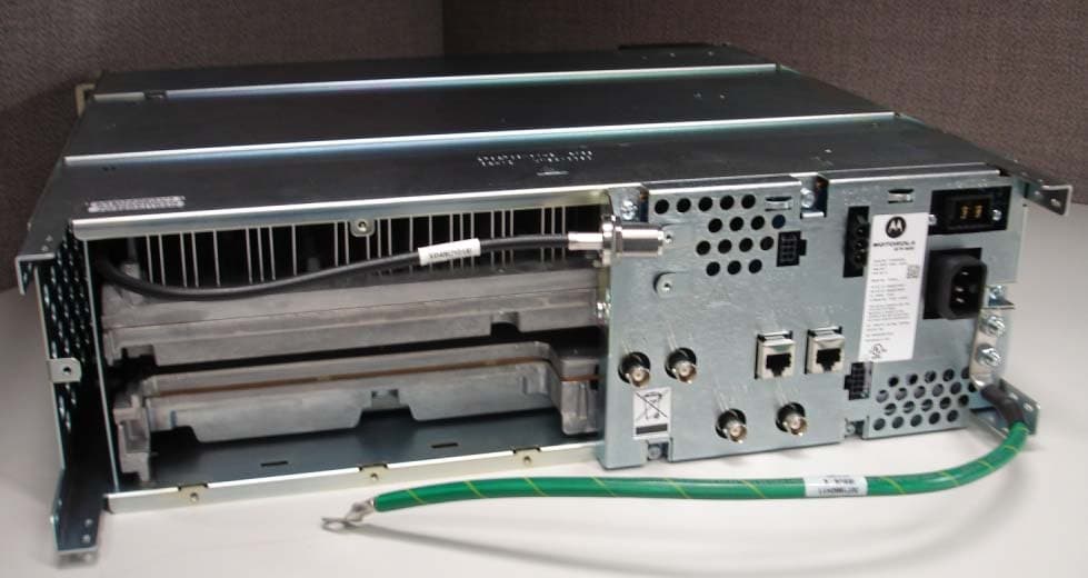
Click to zoom
Application Details
- Equipment Class
- TNB - Licensed Non-Broadcast Station Transmitter
- Date of Grant
- Apr 14, 2013
- Application Purpose
- Original Equipment
- Date of Application
- Apr 14, 2013
- Equipment Note
- Non Broadcast Transmitter
- Frequency Range
- 136.00000000 - 174.00000000
- Company
- Motorola Solutions, Inc.
- Country
- United States
Documents & Files
Document Text
Text extracted from the exhibit documents filed with the FCC. Open a document above to read the original.
Users Manual
APPLICANT: MOTOROLA EQUIPMENT TYPE: ABZ89FC3790B EXHIBIT D User / Operational Manual Operational or User’s Manual The manual should include instruction, installation, operator, or technical manuals with required ‘information to the users’. This manual should include a statement that cautions the user that changes or modifications not expressly approved by the party responsible for compliance could void the user’s authority to operate the equipment. The manual shall include RF Hazard warning statements, if applicable. Draft copy of some of the manual information has been assembled and has been included as part of this filing package. Upon request, published and/or printed manuals will be sent to the commission and/or telecommunication certification body (TCB). All of the descriptions, block diagrams, and schematics that are included in this filing package are current as of the package submittal date. EXHIBIT DESCRIPTION D1-1 Manual Front Matter (Draft) D1-2 Specifications (Draft) D1-3 Field Replaceable Units and Orderable Parts (Draft) D1-4 Tune-Up Procedure D1-5 Racking Configurations D1-6 Functional Description / Operation of Modules (Draft) APPLICANT: MOTOROLA EQUIPMENT TYPE: ABZ89FC3790B EXHIBIT D1-1 User / Operational Manual Manual Front Matter (Draft) Copyrights The Motorola products described in this document may include copyrighted Motorola computer programs. Laws in the United States and other countries preserve for Motorola certain exclusive rights for copyrighted computer programs. Accordingly, any copyrighted Motorola computer programs contained in the Motorola products described in this document may not be copied or reproduced in any manner without the express written permission of Motorola. © 2013 Motorola Solutions, Inc. All Rights Reserved No part of this document may be reproduced, transmitted, stored in a retrieval system, or translated into any language or computer language, in any form or by any means, without the prior written permission of Motorola Solutions, Inc. Furthermore, the purchase of Motorola products shall not be deemed to grant either directly or by implication, estoppel or otherwise, any license under the copyrights, patents or patent applications of Motorola, except for the normal nonexclusive, royalty-free license to use that arises by operation of law in the sale of a product. Disclaimer Please note that certain features, facilities, and capabilities described in this document may not be applicable to or licensed for use on a particular system, or may be dependent upon the characteristics of a particular mobile subscriber unit or configuration of certain parameters. Please refer to your Motorola contact for further information. Trademarks MOTOROLA, MOTO, MOTOROLA SOLUTIONS, and the Stylized M Logo are trademarks or registered trademarks of Motorola Trademark Holdings, LLC and are used under license. All other trademarks are the property of their respective owners. European Union (EU) Waste of Electrical and Electronic Equipment (WEEE) directive The European Union's WEEE directive requires that products sold into EU countries must have the crossed out trash bin label on the product (or the package in some cases). As defined by the WEEE directive, this cross-out trashbin label means that customers and end-users in EU countries should not dispose of electronic and electrical equipment or accessories in household waste. Customers or end-users in EU countries should contact their local equipment supplier representative or service centre for information about the waste collection system in their country. FCC Requirements Radio frequency (RF) transmitters installed at sites within the US must be in compliance with the following FCC regulations: • The station licensee shall be responsible for the proper operation of the station at all times and is expected to provide observations, servicing, and maintenance as often as may be necessary to ensure proper operation. • The transmitter ERP shall not exceed the maximum power specified on the current station authorization. • The frequency of the transmitter must be checked during initial installation of the transmitter, when replacing modules, or when making adjustments that affect the carrier frequency or modulation characteristics. This equipment has been tested and found to comply with the limits for a Class A digital device, according to part 15 of the FCC Rules. These limits are designed to provide reasonable protection against harmful interference to radio communications when the equipment is operated in a commercial environment. This equipment generates, uses, and can radiate radio frequency energy. If not installed properly and used in accordance with the instruction manuals, the equipment may cause harmful interference to radio communications. Operation of some compliant equipment in a residential area may cause harmful interference to radio communications, in which case the user is required to correct the interference. APPLICANT: MOTOROLA EQUIPMENT TYPE: ABZ89FC3790B EXHIBIT D1-1 User / Operational Manual Manual Front Matter (Draft, Continued) About GTR 8000 Base Radio - What Is Covered In This Manual? This manual contains the following chapters: • Chapter 1 GTR 8000 Base Radio Description provides a high-level description of the GTR 8000 Base Radio and the function it serves on your system. • Chapter 2 GTR 8000 Base Radio Theory of Operation explains how the GTR 8000 Base Radio works in the context of your system. • Chapter 3 GTR 8000 Base Radio Installation details installation procedures relating to the GTR 8000 Base Radio. • Chapter 4 GTR 8000 Base Radio Configuration details configuration procedures relating to the GTR 8000 Base Radio. • Chapter 5 GTR 8000 Base Radio Optimization contains optimization procedures and recommended settings relating to the GTR 8000 Base Radio. • Chapter 6 GTR 8000 Base Radio Maintenance describes periodic maintenance procedures relating to the GTR 8000 Base Radio. • Chapte…
Text truncated - open the document above for the full version.
External Photos
APPLICANT: MOTOROLA EQUIPMENT TYPE: ABZ89FC3790B EXHIBIT C1-1 Photographs of the Device External Front View of Base Radio APPLICANT: MOTOROLA EQUIPMENT TYPE: ABZ89FC3790B EXHIBIT C1-2 Photographs of the Device External Front View of Base Radio, Front Panel Removed APPLICANT: MOTOROLA EQUIPMENT TYPE: ABZ89FC3790B EXHIBIT C1-3 Photographs of the Device External Front View of Base Radio, Alternate Racking of Base Radio in ‘GTR 8000 Expandable Site Sub-system’ Configuration APPLICANT: MOTOROLA EQUIPMENT TYPE: ABZ89FC3790B EXHIBIT C2-1 Photographs of the Device External Back View of Base Radio
ID Label/Location Info
APPLICANT: MOTOROLA EQUIPMENT TYPE: ABZ89FC3790B EXHIBIT A1 Equipment Label FCC / IC Identification Numbers The FCC Identifier (FCC ID) is made up of the Grantee Code, supplied by the FCC, and an Equipment Product Code. This equipment product code may be to 14 characters in length, and is assigned by the grantee (applicant). The Grantee Code for this product is ABZ The Equipment Product Code for this product is 89FC3790B The entire FCC ID number is ABZ89FC3790B The Industry Canada (IC) identification consists of the certification / registration number as well as the IC model number. The certification / registration number is made up of Company Number (CN) assigned by Industry Canada, and the Unique Product Number (UPN) assigned by Motorola. The IC model number is the unique model number of the radio assigned by Motorola. The Company Number is 109AB The Certification / Registration Number for this product is 109AB-3790B The IC Model Number is T7039-VHF APPLICANT: MOTOROLA EQUIPMENT TYPE: ABZ89FC3790B EXHIBIT A2-1 Equipment Label FCC / IC Identification Label A representative image of the FCC / IC Identification label is shown below. This label is generated as part of the standard manufacturing process and is printed in the factory. Much of the information that is on the label, such as serial number, model number, etc. is driven by the ordering process and is unique per customer order. Serial No: F.O. Page No: Item No: Model No. T7039A TX FCC ID: A BZ89FC3790B RX FCC ID: ABZ89FR3791B IC: 109AB-3790B IC Model No: T7039-VHF This device complies with Part 15 of the FCC Rules. Operation is subject to the condition that this device does not cause harmful interference. 90-230V 10A Max. 50/60 Hz 48V 18A US: ABZNINANT7039 Assembled in USA I.T.E. 31 NH FCC / IC Identification Label APPLICANT: MOTOROLA EQUIPMENT TYPE: ABZ89FC3790B EXHIBIT A2-2 Equipment Label FCC / IC ID Label The location of the identification label is on the back of the radio, as shown in the photograph below. Location of FCC/ IC Identification Label
Internal Photos
APPLICANT: MOTOROLA EQUIPMENT TYPE: ABZ89FC3790B EXHIBIT C3-1.1 Photographs of the Device Internal Front View – Transceiver Module Transceiver Module without the Transceiver Option Card (TOC) Transceiver Module with the Transceiver Option Card (TOC) Installed Front View of Base Radio Showing Transceiver Module with TOC Installed and Identifying Connections APPLICANT: MOTOROLA EQUIPMENT TYPE: ABZ89FC3790B EXHIBIT C3-1.2 Photographs of the Device Internal Front View – Transceiver Module Circuit Board Top View APPLICANT: MOTOROLA EQUIPMENT TYPE: ABZ89FC3790B EXHIBIT C3-1.3 Photographs of the Device Internal Front View – Transceiver Module, Control Section APPLICANT: MOTOROLA EQUIPMENT TYPE: ABZ89FC3790B EXHIBIT C3-1.4 Photographs of the Device Internal Front View – Transceiver Module, Exciter Section APPLICANT: MOTOROLA EQUIPMENT TYPE: ABZ89FC3790B EXHIBIT C3-1.5 Photographs of the Device Internal Front View – Transceiver Module, Receiver Section APPLICANT: MOTOROLA EQUIPMENT TYPE: ABZ89FC3790B EXHIBIT C3-2 Photographs of the Device Internal Front View – Power Amplifier Module, Cover Removed APPLICANT: MOTOROLA EQUIPMENT TYPE: ABZ89FC3790B EXHIBIT C3-3.1 Photographs of the Device Internal Front View – Power Supply Module APPLICANT: MOTOROLA EQUIPMENT TYPE: ABZ89FC3790B EXHIBIT C3-3.2 Photographs of the Device Internal Front View – Power Supply Module, Circuit Boards, Top View APPLICANT: MOTOROLA EQUIPMENT TYPE: ABZ89FC3790B EXHIBIT C3-4 Photographs of the Device Internal Front View – Backplane APPLICANT: MOTOROLA EQUIPMENT TYPE: ABZ89FC3790B EXHIBIT C3-5 Photographs of the Device Internal Front View – Transceiver Option Card (TOC) APPLICANT: MOTOROLA EQUIPMENT TYPE: ABZ89FC3790B EXHIBIT C4-1 Photographs of the Device Internal Back View – Transceiver Module APPLICANT: MOTOROLA EQUIPMENT TYPE: ABZ89FC3790B EXHIBIT C4-2 Photographs of the Device Internal Back View – Power Amplifier Module APPLICANT: MOTOROLA EQUIPMENT TYPE: ABZ89FC3790B EXHIBIT C4-3 Photographs of the Device Internal Back View – Power Supply Module, Circuit Boards, Back View APPLICANT: MOTOROLA EQUIPMENT TYPE: ABZ89FC3790B EXHIBIT C4-4 Photographs of the Device Internal Back View – Backplane APPLICANT: MOTOROLA EQUIPMENT TYPE: ABZ89FC3790B EXHIBIT C4-5 Photographs of the Device Internal Back View – Transceiver Option Card (TOC)
Parts List/Tune Up Info
APPLICANT: MOTOROLA EQUIPMENT TYPE: ABZ89FC3790B EXHIBIT D1-4 User / Operational Manual Tune-Up Procedure There is no field tune-up procedure. All adjustments are software controlled and are pre-set at the factory. Certain station operating parameters can be changed via man-machine interface (MMI) commands, within predetermined limits. Examples include transmit / receiver operating frequencies and transmitter power level.
Test Report
APPLICANT: MOTOROLA EQUIPMENT TYPE: ABZ89FC3790B EXHIBIT E (Sheet 1 of 2) Report on Test Measurements Measurements Report The measurement report shows compliance information against the pertinent technical standards. Each parameter is measured generally at the low end, middle, and at the high end of the applicable frequency band. Each section of the report contains either verbiage or graphs which show compliance to applicable standards as required, explains testing method used, and indicates what the applicable specification is. Information and performance relative to 25 kHz ‘wideband’ operation is included in the report. Although wideband operation in the 150-174 MHz and 421-512 MHz bands is no longer allowable for rule part 90 in the US, it is available for other FCC rule parts and in other countries, including Industry Canada. The time division multiple access (TDMA) mode of operation provides two voice paths in a 12.5 kHz channel bandwidth and a data rate of 9600 bits per second or 12,000 bits per second in a channel bandwidth of 12.5 kHz. This is equivalent to one voice path per 6.25 kHz of channel bandwidth and 4800 bits per second or greater in a 6.25 kHz channel bandwidth. The GTR 8000 conforms to the spectrum efficiency requirements of FCC rule § 90.203 (j) (5). A list of test equipment for all sections, and certification signoff page are included at the end of the measurement report. SUBMITTED MEASURED DATA -- INDEX EXHIBIT DESCRIPTION E1-1 RF Output-Data E1-2 Occupied Bandwidth, Digital Emissions: Setup, Specifications, and Index E1-2.1, 2, 3 Linear Simulcast Modulation (LSM) E1-2.4, 5, 6 Compatible 4-Level Frequency Modulation (C4FM) E1-2.7, 8, 9 H-DQPSK, P25 Two Slot TDMA Digital Modulation E1-2.10, 11, 12 Trunking Control Data 3600 bps FSK Modulation, 25 kHz Channels E1-2.13, 14, 15 Trunking Control Data 3600 bps FSK Modulation, 12.5 kHz Channels E1-3 Conducted Spurious Emissions: Setup, Specifications, and Index E1-3.1 LSM Conducted Spurious Harmonic Emissions, Power 60 Watts E1-3.2 LSM Conducted Spurious Harmonic Emissions, Power 2 Watts E1-3.3 C4FM Conducted Spurious Harmonic Emissions, Power 100 Watts E1-3.4 C4FM Conducted Spurious Harmonic Emissions, Power 2 Watts E1-3.5 Analog Conducted Spurious Harmonic Emissions, Power 100 Watts E1-3.6 Analog Conducted Spurious Harmonic Emissions, Power 2 Watts E1-3.7, 8, 9 Conducted Spurious Emission Spectrum, 200 MHz Span, Power Output at 60 Watts, LSM E1-3.10, 11, 12 Conducted Spurious Emission Spectrum, 200 MHz Span, Power Output at 100 Watts, C4FM E1-3.13, 14, 15 Conducted Spurious Emission Spectrum, 200 MHz Span, Power Output at 100 Watts, Analog E1-4 Radiated Spurious Emissions: Setup, Specifications, and Index E1-4.1 LSM Radiated Spurious Harmonic Emissions, Power 60 Watts E1-4.2 LSM Radiated Spurious Harmonic Emissions, Power 2 Watts E1-4.3 Analog Radiated Spurious Harmonic Emissions, Power 100 Watts E1-4.4 Analog Radiated Spurious Harmonic Emissions, Power 2 Watts APPLICANT: MOTOROLA EQUIPMENT TYPE: ABZ89FC3790B EXHIBIT E (Sheet 2 of 2) Report on Test Measurements Measurements Report SUBMITTED MEASURED DATA – INDEX (Continued) EXHIBIT DESCRIPTION E1-5 Frequency Stability: Setup, Specifications, and Index E1-5.1 Frequency Stability Vs Temperature E1-5.2 Frequency Stability Vs Voltage E1-6 Frequency Transient Behavior: Setup, Specifications, Index E1-6.1, 2, 3 Frequency Transient Behavior, 25 kHz Channel Key-Up E1-6.4, 5, 6 Frequency Transient Behavior, 25 kHz Channel De-Key E1-6.7, 8, 9 Frequency Transient Behavior, 12.5 kHz Channel Key-Up E1-6.10, 11, 12 Frequency Transient Behavior, 12.5 kHz Channel De-key E1-7 Audio Frequency Response – Modulation Characteristics: Setup, Specifications, Index E1-7.1, 2, 3 Audio Frequency Response – Modulation Characteristics, 25 kHz Channels E1-7.4, 5, 6 Audio Frequency Response – Modulation Characteristics, 12.5 kHz Channels E1-8 Audio Modulation Limiting – Modulation Characteristics: Setup, Specifications, Index E1-8.1 Audio Modulation Limiting – Modulation Characteristics, 25 kHz Channels E1-8.2 Audio Modulation Limiting – Modulation Characteristics, 12.5 kHz Channels E1-9 Occupied Bandwidth Description –Analog Modulation E1-9.1, 2, 3 Occupied Bandwidth Plot – Analog, no sub audible signaling, 25 kHz Channels E1-9.4, 5, 6 Occupied Bandwidth Plot – Analog, Private Line signaling, 25 kHz Channels E1-9.7, 8, 9 Occupied Bandwidth Plot – Analog, Digital Private Line signaling, 25 kHz Channels E1-9.10, 11, 12 Carrier with 2500 Hz Audio Tone and 150 bps Low Speed Data Signaling, 25 kHz Channels E1-9.13, 14, 15 Carrier with 2500 Hz Audio Tone and 300 bps Low Speed Data Signaling, 25 kHz Channels E1-9.16, 17, 18 Carrier with 2500 Hz Audio Tone, no sub audible signaling, 12.5 kHz Channels E1-9.19, 20, 21 Carrier with 2500 Hz Audio Tone and Private Line (PL) Signaling, 12.5 kHz Channels E1-9.22, 23, 24 Carrier with 2500 Hz Audio Tone and Digital Private Line (DPL) Signaling, 12.5 kHz Channels E1-9.25, 26, 27 Carrier with 2500 Hz Audio Tone and 150 bps Low Speed Data Signaling, 12.5 kHz Channels E1-9.28, 29, 30 Carrier with 2500 Hz Audio Tone and 300 bps Low Speed Data Signaling, 12.5 kHz Channels E1-11 Test Equipment Used E1-12 Statement of Certification APPLICANT: MOTOROLA EQUIPMENT TYPE: ABZ89FC3790B EXHIBIT E1-1 Report on Test Measurements RF Power Output Data The RF power output was measured with the indicated voltage applied to and current into the final RF amplifying device. The DC current indicated is the total for the final RF amplifier stage, consisting of six parallel power transistors. Linear Modulation Mode: 138 MHz 155 MHz 174 MHz Measured RF output 60 60 60 Watts, Average DC Voltage, final RF amplifier stage/stages 19.8 19.8 19.8 Volts DC Current, final RF amplifier stage/stages 9.0 10.0 8.5 Amperes Input power for final RF amplifying device(s) 178 198 168 Watts Primary Radio Input Supply Voltage 120 120 120 Volts AC Minimum Measured RF output 2 2 2 Watts, Average Normal DC Voltage…
Text truncated - open the document above for the full version.
Contact Information
Applicant
Matthew Nawrocki
Non-Technical Contact
Motorola, Inc.Greg Alms
[email protected]8475768450
Technical Specifications
| # | Rule Parts | Frequency Range | Power Output | Emission | Tolerance |
|---|---|---|---|---|---|
| 13 | 22,74,80,9 | 136 MHz - 174 MHz | 100 W | 10K0F1D | 2.5 ppm |
Other Applications from Motorola Solutions, Inc.

ABZ89FT4940
Aug 06, 2026Non Broadcast Transmitter
Equipment Class
TNB - Licensed Non-Broadcast Station TransmitterABZ89FT4950
Jun 25, 2026Non-Broadcast Transmitter
Equipment Class
TNB - Licensed Non-Broadcast Station TransmitterABZ89FT5901
Jun 20, 2024Non Broadcast Transmitter
Equipment Class
TNB - Licensed Non-Broadcast Station Transmitter
ABZ99FT5101B
May 02, 2023Non Broadcast Transmitter
Equipment Class
PCB - PCS Licensed Transmitter
ABZ99FT3095B
Mar 26, 2023Non Broadcast Transmitter
Equipment Class
TNB - Licensed Non-Broadcast Station Transmitter