ABZ89FC48165.7GHz Fixed Wireless (U-NII)
Motorola Solutions, Inc.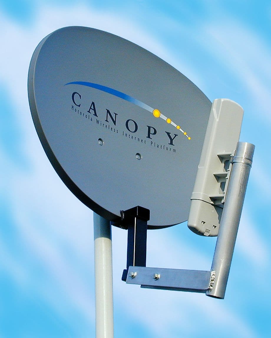
Click to zoom
Application Details
- Equipment Class
- NII - Unlicensed National Information Infrastructure TX
- Date of Grant
- Dec 19, 2001
- Application Purpose
- Original Equipment
- Date of Application
- Dec 19, 2001
- Equipment Note
- 5.7GHz Fixed Wireless (U-NII)
- Frequency Range
- 5745.00000000 - 5805.00000000
- Company
- Motorola Solutions, Inc.
- Country
- United States
Documents & Files
Document Text
Text extracted from the exhibit documents filed with the FCC. Open a document above to read the original.
Users Manual
C A N O P Y Motorola Wireless Internet Platform Page 24 Specifications Operating Frequency Range U-NII Mid band 5. 7 4 5 to 5. 8 0 5 GHz Access Method TDD/TDMA Data Rate 10 Mbps Modulation Type High Index BFSK/4FSK (Optimized for interference rejection) Carrier to Interference (C/I) 3dB Ber 1*10 -4 Receiver Sensitivity -84dBm 1*10 -4 Error Floor Better than 10 -9 BER, unfaded Operating Range (All Weather) Up to 2 miles with integrated antenna , Transmitter Power Meets FCC UNII ERP Limit DC Power 24 VDC @ 0.3 Amp (active state) Interface 10 Base-T, RJ45 Rate auto negotiated (802.3 compliant) Protocols Used by CANOPY IPV4, UDP, TCP, ICMP, Telnet, HTTP, FTP, SNMP Protocols Supported by CANOPY Switched Layer 2 Transport with support for all common Ethernet protocols including IPV6, NetBIOS, DHCP, IPX, etc. Software Upgrade Path Remotely downloaded into FLASH via RF link Network Management HTML, TELNET, SNMP Environmental Wind 190 km/hr Humidity Relative Humidity 95% at 35 ° C Temperature -30 ° to +55 ° C Physical Dimensions 11.75”H x 3.4”W x 1.1”D (not counting mounting bracket) x 3.4”D (including mounting bracket) Weight Approx 1 lb, 0.5 kg C A N O P Y Motorola Wireless Internet Platform Page 1 Getting Started with Motorola CANOPY TM AP REV 11/26/01 C A N O P Y Motorola Wireless Internet Platform Page 2 Warranty Information Motorola offers a warranty covering a period of 90 days from the date of purchase by the retail customer. If a product is found defective during the warranty period, Motorola will repair or replace the product with the same or a similar model, which may be a reconditioned unit, without charge for parts or labor. C A N O P Y Motorola Wireless Internet Platform Page 23 Packet Stats Information on Packet Stats is for tech support personnel only. C A N O P Y Motorola Wireless Internet Platform Page 22 Sessions Information on Sessions is for tech support personnel only. C A N O P Y Motorola Wireless Internet Platform Page 3 Congratulations! You have purchased a Motorola CANOPY radio, the laest innovation in high speed wireless networking. The Motorola CANOPY radio lets you easily network at high speeds with no wiring. - Network speeds of 10baseT. - Small compact design - No special set up on your PC. Getting to Know your Radio. The base cover snaps off to expose the RJ45 connector where the Ethernet Cable will be plugged in, as well as connection LEDs used for dagnostics. The base cover is released by depressing a release lever on the back of the base cover. Ethernet Cable Base Cover Release Lever Base Cover Ethernet Cable Canopy AP RJ45 Connector Connection LEDs Base Cover C A N O P Y Motorola Wireless Internet Platform Page 4 Installing CANOPY Mount from 1 to 6 CANOPY AP radios in a location where it is facing the community to be served. Pick a location, pole, tower, rooftop or other structure which provides an unobstructed view over the rooftops of the surrounding buildings. 6 CANOPY AP radios on a pole will serve the surrounding community in all directions. Canopy AP Radios Optimum Access Point height on building or pole should minimally clear the surrounding community C A N O P Y Motorola Wireless Internet Platform Page 21 Time & Date Each Canopy AP Unit can be configur ed with time & date. Further, the entered Time & Date are automatica lly conveyed over the air to all registered Canopy Subscriber Modules at the time of their next time of registration . Time & Date are configured automa tically in multiple Canopy AP Unit sites where the Canopy AP Junction contains GPS. C A N O P Y Motorola Wireless Internet Platform Page 20 Link Test In concert with the LUID select page, the radio link to the currently selected Canopy SM Unit may be tested. C A N O P Y Motorola Wireless Internet Platform Page 5 Mounting Your Canopy AP Units - IMPORTANT NOTE: To comply with FCC RF exposure compliance requirements, the following antenna installation and device operating configurations must be satisfied. The Canopy AP Units must be installed to provide a separation distance of at least 20cm from all persons and must not be co-located or operating in conjunction with any other antenna or transmitter. Installers must follow the Canopy AP Unit installation instructions and transmitter operating conditions for satisfying RF exposure compliance. - The Canopy AP Units can be mounted in a variety of ways. Mounting to a typical rooftop antenna mast is illustrated above as an example using readily available stainless steel hose clamps or any equivalent fasteners. - The Canopy AP Units should be installed away from the service mast and grounding of masts or brack ets must be in accordance with applicable requirements within sect ion 810 of the National Electrical Code (NEC). 1 Canopy AP Radio Stainless Steel Hose Clamps or any Suitable Equivalent Typical Antenna Mast 6 Canopy AP Radios C A N O P Y Motorola Wireless Internet Platform Page 6 Connecting Your Single Canopy AP Unit - Connect a CAT-5 Ethernet cable, such as Belden-E Datatwist ® 5E 1585LC, between the power adapter Ethernet patch and the RJ45 socket on the CANOPY AP. - Plug the AC Adapter into an AC outlet. Plug the other side of the power adapter’s Ethernet patch into a computer Ethernet port, hub, router, or Ethernet switch. - If connecting to a COMPUTER , use a Straight-Thru Ethernet cable . If connecting to a HUB, SWITCH, or ROUTER , use a Cross-Over Ethernet cable . AC Adapter Ethernet Cable CANOPY AP Fixed Network Access Single CANOPY AP Site C A N O P Y Motorola Wireless Internet Platform Page 19 View Subscriber Module In concert with the LUID Select pa ge, the currently selected Canopy Subscriber Module internal web pages can be accessed. Once selected, other pages within the currently se lected Subscriber Module can be accessed. In this way, the system prov ider can examine, or even reconfig- ure registered Canopy Subscriber Modules. C A N O P Y Motorola Wireless Internet Platform Page 18 LUID Select The user can select any of the…
Text truncated - open the document above for the full version.
Cover Letter(s)
FCC ID: ABZ89FC4816 Request for Confidentiality In accordance with 47 C.F.R. Section 0.459, we, Motorola Inc., hereby request confidentiality for the block diagram, schematic and product description presented for certification. In support of the Request for Confidentiality, the following is stated: Enclosed within this application is technical information which we deem to be trade secrets and proprietary. If made public, the information might be used to our disadvantage. To assist in assuring that we receive the full value of our product and protect its competitive posture, we respectfully request this grant of confidentiality. Motorola Inc.
ID Label/Location Info
Motorola Broadband Wireless Technology Center FCC ID: ABZ89FC4816 This device complies with part 15 of the FCC rules. Operation is subject to the following two conditions; (1) This device may not cause harmful interference, and (2) This device must accept any interference received, including interference that may cause undesired operation Motorola "Canopy" Fixed wireless access product FCC ID label details Label will be moulded into the rear of the plastic housing. Dec 12, 2001 Fig 1: Details Motorola Broadband Wireless Technology Center FCC ID: ABZ89FC4816 This device complies with part 15 of the FCC rules. Operation is subject to the following two conditions; (1) This device may not cause harmful interference, and (2) This device must accept any interference received, including interference that may cause undesired operation Fig 2: Actual Size
Internal Photos
WHISP unit #170 Component Side: WHISP Unit #170, Solder Side: 27 WHISP unit #440 Component Side: 28 WHISP Unit #440, Solder Side:
RF Exposure Info
Motorola FCC ID: ABZ89FC4816 The Motorola Canopy device requesting certification is excluded from RF exposure because it is a fixed transmitter mounted on outdoor permanent structures and satisfies the MPE requirements of 2.1091 because of its low power.
Test Report
1 Canopy 5700 Conducted Test 16 December 2001 Compliance testing with FCC rules part 15.407 was performed in both conducted and radiated tests. The power spectral density measurement was setup on WHISP unit serial #440 before an antenna was added. The radio was connected to an HP (Agilent) 8596E Spectrum analyzer. Measurements were taken in 0Hz span with the spectrum analyzer synchronized to the transmitter’s data burst. This allowed the analyzer to make time gated power measurements of the radio. The test setup diagram is as follows: Silent carrier signal from the radio under test was used to calibrate the spectrum analyzer through the adjustable attenuator for a carrier power of 0 dBm. TX bit error test pattern was initiated to maximize the transmit duty cycle and data throughput for the radio under test. A testing program on the PC computer collected the 0Hz span power sweeps over a 60MHz frequency band. Post processing integrated the power measurements into the 1MHz measurement bandwidths for the plotted power spectral density. The data was offset via the radiated carrier power measurement (+29.05dBm) and plotted as shown. IBM PC Radio Under Test Ethernet Connection Spectrum Analyzer Oscilloscope Burst Trigger GPIB RF Cable RF Cable Adjustable Attenuator 2 The plot shown above indicates the worst case results for the radio operation in the frequency band 5725-5825MHz. The results show that at the carrier frequency the maximum power in a 1MHz BW is +16.05dBm radiated. In the region +/-25 to 26MHz the maximum amplitude was –48.45dBm or 31.4dB better than the maximum bandedge power of -17dBm radiated. In the region +/-20 to 21MHz the maximum amplitude was –34.25dBm or 17.2dB better than the maximum bandedge power of -17dBm radiated. Signals > +/-31MHz were below the measurement noise floor. From these measurements it can be seen that the WHiSP radio #440 passses the FCC part 15 specifications. 3 Canopy 5700 Radiated Test 16 December 2001 A Canopy 5700 unit, serial #440, was tested outdoors to check compliance with FCC requirement 15.209, restricted band emissions. The testing was done using a model 3115 and a model 3116 calibrated dual-ridged waveguide-horn antennas manufactured by EMCO, Inc., an Agilent 8564EC 40GHz spectrum analyzer, and a laptop to control the DUT and take data from the spectrum analyzer. The two antennas combined allowed a frequency measurement range of 1GHz to 40GHz. The spatial separation between the EMCO horn antennas and the DUT was maintained at 1 or 3 meters during the test. The FCC requirement for restricted band emissions is stated in terms of field strength at 500uV/m at a distance of 3 meters. Using the free space impedance of 377 ohms, the equivalent power density is –61.78dBm/m 2 . This power density number was used as the pass/fail criteria for the test. Cable losses, antenna gains, and other correction factors were entered into an Excel spreadsheet along with the results of the testing. To calculate the power density at the horn antennas, the power level received by the antenna is offset by the log ratio of the effective aperture of the antenna to one square meter. The calculation of the effective aperture is done using: A em = e cd (? 2 /4p)D o, D o is the directivity of the antenna, e cd is the efficiency, and ? is the wavelength of the frequency under observation. In the equation, e cd and D o may be replaced by the numeric gain of the antenna. Using the calibration data from the manufacturer, the effective area of the antenna was computed for each measurement frequency and the appropriate dB correction factor applied. The operating frequency of the radio presented a challenge to measuring the harmonics radiated by the radio. Since the highest harmonic to be measured is 34GHz (as the seventh harmonic exceeded the FCC frequency limit of 40GHz, it was not measured), finding test equipment that possess reasonable noise figures and obtaining coax cables with mode-free moderate loss is difficult. The resolution bandwidth of 1MHz also adds to the problem of making an effective radiated power measurement. As an aid in performing these measurements, the radio was designed with the ability to operate in continuous-wave mode (a proprietary mode of operation not available to the normal user), permitting the use of narrow bandwidths on the analyzer. In normal operation, logic in the radio will prevent the transmitter from operating in case of frequency error, and the resident firmware and hardware logic prevent transmissions when there is no data to be sent. 4 The picture below shows the configuration of the test set-up: 5 The test antennas and test radio were mounted on adjustable tripods and placed 1 or 3 meters apart, depending on the measurement antenna type. Absorbing panels were placed on the ground to reduce the effects of ground reflections. The test setup diagram is as follows: Two different antennas were used, an EMCO model 3115 ridged-waveguide horn antenna covering the 1 to 18GHz frequency range, and an EMCO model 3116 ridged- waveguide horn antenna covering the 18 to 40GHz frequency range. The radio has a CW mode for testing purposes and was used to measure the harmonic levels radiated from the radio. With no modulation, the measurement bandwidth could be reduced below 1MHz, allowing greater dynamic range for the test equipment. Measurements were made using a 30 kHz resolution bandwidth and a 1MHz bandwidth. Data used for calculations was taken from the 1MHz RBW measurements. Where no clearly discernable signal could be seen, the magnitude difference between signal and noise was set equal to a minimum value to avoid computational errors in the spreadsheet. Harmonic level as a function of channel frequency was reviewed and the RF channel possessing the highest harmonic level was used. Where harmonic levels were not strongly tied to the channel frequency, a nominal frequency of 5800MHz was used. Data from the analyzer was transferred to the laptop co…
Text truncated - open the document above for the full version.
Test Setup Photos
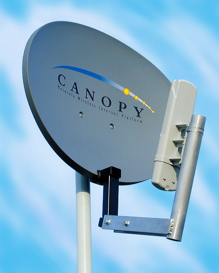
15 The Canopy 5700 radio can be equipped with a passive reflector to increase the ERP of the radio when setting up long distance links. The FCC rules given in part 15.407, subpart (a), paragraph (3), states that for a U-NII device employed in a fixed-point application in the 5725 to 5825MHz band, an external antenna of up to +23dBi gain (providing an ERP of up to +53dBm) may be used. A test reflector providing an additional 19 dBi gain was attached to the Canopy 5700 radio. The radio assembly was mounted on a pole with the EMCO antennas located 20 meters away to avoid near-field measurement error due to the high gain of the reflector (utilizing the relationship 2D 2 /? , with D= largest antenna dimension, the minimum distance to avoid near field errors for the fundamental frequency was 13.48meters). On-channel power and harmonic content measurements were performed and used to calculate equivalent 3 meter data. The test layout was configured as below: Radiated data was analyzed to determine the RF channel with the highest harmonic level. Where harmonic levels were the same regardless of operating frequency, data from the nominal (5800MHz) frequency was used. The resulting plots are shown as follows: 4 The picture below shows the configuration of the test set-up:
Contact Information
Applicant
Matthew Nawrocki
Technical Contact
Motorola Broadband WirelessGary Schultz
[email protected]1 847 538 2666
50 E. Commerce Drive · Schaumburg, Illinois · United States
Non-Technical Contact
Motorola Broadband WirelessPat Martello
1 847 538 5200
Test Firm
DLS Electronic Systems, Inc.William Stumpf
Technical Specifications
| # | Rule Parts | Frequency Range | Power Output | Tolerance |
|---|---|---|---|---|
| 2 | 15E | 5.75 GHz - 5.80 GHz | 63 W | 25 ppm |
Other Applications from Motorola Solutions, Inc.

ABZ89FT4940
Aug 06, 2026Non Broadcast Transmitter
Equipment Class
TNB - Licensed Non-Broadcast Station TransmitterABZ89FT4950
Jun 25, 2026Non-Broadcast Transmitter
Equipment Class
TNB - Licensed Non-Broadcast Station TransmitterABZ89FT5901
Jun 20, 2024Non Broadcast Transmitter
Equipment Class
TNB - Licensed Non-Broadcast Station Transmitter
ABZ99FT5101B
May 02, 2023Non Broadcast Transmitter
Equipment Class
PCB - PCS Licensed Transmitter
ABZ99FT3095B
Mar 26, 2023Non Broadcast Transmitter
Equipment Class
TNB - Licensed Non-Broadcast Station Transmitter