ABZ89FC4818-DNon-Broadcast Transmitter
Motorola Solutions, Inc.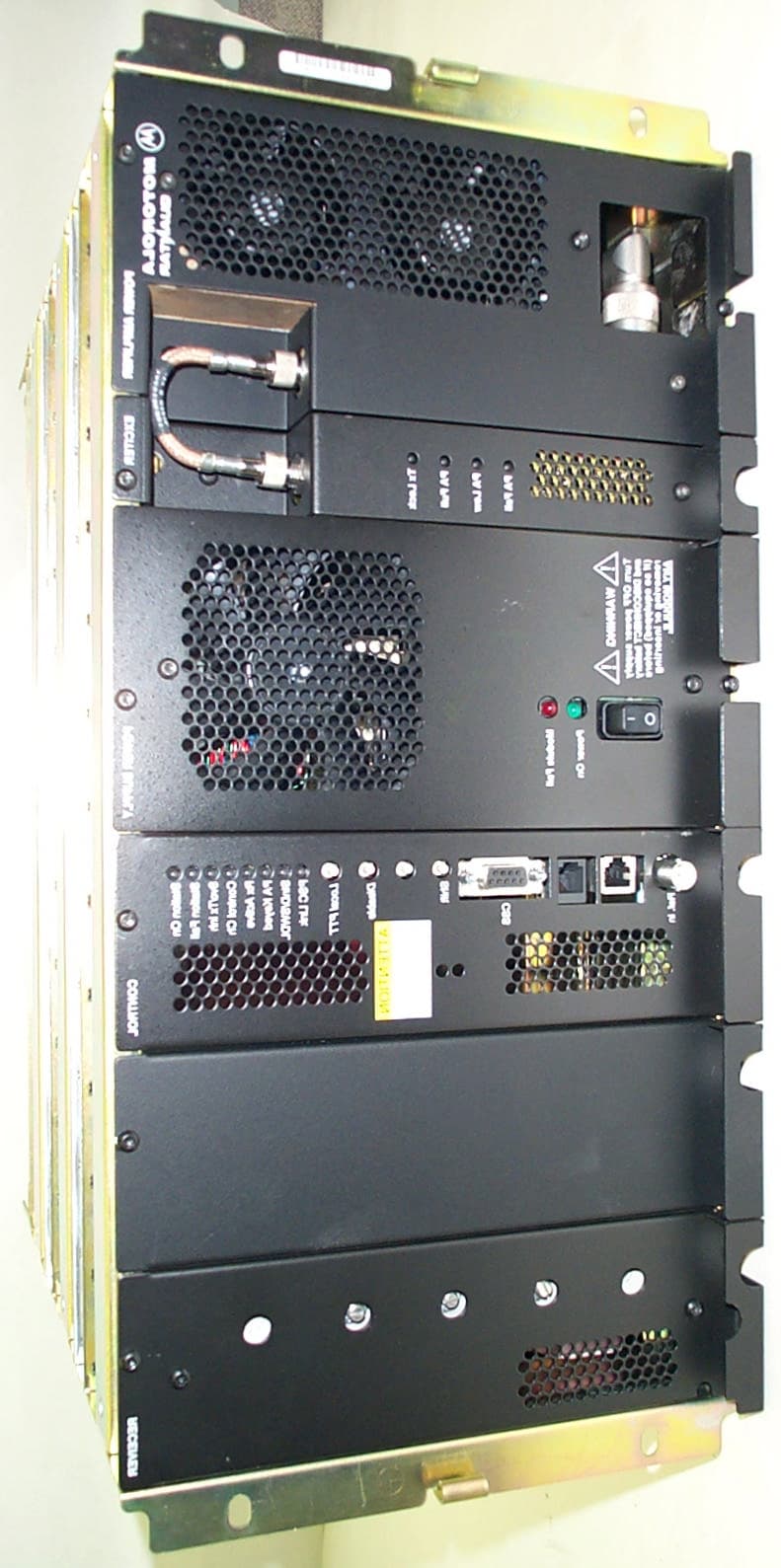
Click to zoom
Application Details
- Equipment Class
- TNB - Licensed Non-Broadcast Station Transmitter
- Date of Grant
- Dec 05, 2002
- Application Purpose
- Original Equipment
- Date of Application
- Dec 05, 2002
- Equipment Note
- Non-Broadcast Transmitter
- Frequency Range
- 494.00000000 - 512.00000000
- Company
- Motorola Solutions, Inc.
- Country
- United States
Documents & Files
Document Text
Text extracted from the exhibit documents filed with the FCC. Open a document above to read the original.
Users Manual
APPLICANT: MOTOROLA INC. EQUIPMENT TYPE: ABZ89FC4818-D EXHIBIT 8 INSTRUCTION MANUALS Draft copy of the of the front matter of the following instruction manual is enclosed with this submission: 68P81095E55-C .........................................................................Quantar Digital Capable Station For Conventional, ASTRO 6809 Trunking, and IntelliRepeater Systems Instruction Manual Other system and radio / configuration service software manuals are available to support the product and system in operation. They can be provided to the Commission upon request. APPLICANT: MOTOROLA INC. EQUIPMENT TYPE: ABZ89FC4818-D EXHIBIT 9 TUNE-UP PROCEDURE This exhibit contains the tune-up procedure as it will appear in the Configuration Service Software (CSS) manual. The following adjustments comprise the total transmitter alignment: 1. Reference Oscillator 2. Transmitter Power Output 3. Transmit Deviation Control 4. Reference Modulation Compensation Note: All adjustments are factory pre-set and do not require alignment under normal operating conditions. In the event alignment is needed, refer servicing to qualified radio maintenance personnel only. TEST EQUIPMENT Description Recommended model 1.Service MonitorMotorola R-2001 or equivalent 2.PC with CSS TRANSMITTER ALIGNMENT PROCEDURE CSS/RSS Port: A 9-pin D connector is provided on the station control module front panel to allow service personnel to connect a PC loaded with the Configuration Service Software (CSS) and perform programming and maintenance tasks via this TIA RS-232 port. The following pages of this exhibit will show the important alignment screens. EXHIBIT DESCRIPTION 9AReference Oscillator Alignment Screen 9BTransmitter Power Output Alignment Screen 9CTransmitter Deviation Alignment Screen 9DReference Modulation Compensation Alignment Screen All adjustments are software controlled and are pre-set at the factory. Certain station operating parameters can be changed via man-machine interface (MMI) commands, within predetermined limits. Examples include transmit / receiver operating frequencies and power level. APPLICANT: MOTOROLA INC. EQUIPMENT TYPE: ABZ89FC4818-D EXHIBIT 9A TUNE-UP PROCEDURE - Reference Oscillator Alignment Screen APPLICANT: MOTOROLA INC. EQUIPMENT TYPE: ABZ89FC4818-D EXHIBIT 9B TUNE-UP PROCEDURE - Transmitter Power Output Alignment Screen APPLICANT: MOTOROLA INC. EQUIPMENT TYPE: ABZ89FC4818-D EXHIBIT 9C TUNE-UP PROCEDURE - Transmitter Deviation Alignment Screen APPLICANT: MOTOROLA INC. EQUIPMENT TYPE: ABZ89FC4818-D EXHIBIT 9D TUNE-UP PROCEDURE - Reference Modulation Compensation Alignment Screen Instruction Manual 68P81095E05-C TM Digital-Capable Station For Conventional,ASTRO, 6809 Trunking ,andIntelliRepeaterSystems VHF Ċ 25W & 125W UHF Ċ 25W ,100W ,& 110W 800 MHz Ċ 20W & 100W 900 MHz Ċ 100W PRELIMINARY COMPUTER SOFTWARE COPYRIGHTS The Motorola products described in this instruction manual may include copyrighted Motorola computer programs stored in semiconductor memoriesorothermedia.LawsintheUnitedStatesandothercountriespreserveforMotorolacertainexclusiverightsforcopyrightedcomputer programs, including the exclusive right to copy or reproduce in any form the copyrighted computer program. Accordingly, any copyrighted MotorolacomputerprogramscontainedintheMotorolaproductsdescribedinthisinstructionmanualmaynotbecopiedorreproducedinany mannerwithouttheexpresswrittenpermissionofMotorola.Furthermore,thepurchaseofMotorolaproductsshallnotbedeemedtogranteither directlyorbyimplication,estoppel,orotherwise,anylicenseunderthecopyrights,patentsorpatentapplicationsofMotorola,exceptforthenormal non-exclusive, royalty free license to use that arises by operation of law in the sale of a product. EPS-34440-B COMMERCIAL WARRANTY (STANDARD) Motorolaradiocommunicationsproductsarewarrantedtobefreefromdefectsinmaterialandworkmanshipfora period of ONE (1) YEAR, (except for crystals and channel elements which are warranted for a period of ten (10) years)fromthedateofshipment.Parts,includingcrystalsandchannelelements,willbereplacedandlaborwillbe providedfreeofchargeforthefullwarrantyperiod.Thereafterpurchasermustpayforthelaborinvolvedinrepairing the product or replacing the parts at the prevailing rates together with any transportation charges to or from the place where warranty service is provided. This express warranty is extended by Motorola Communications and Electronics,Inc., 1301 E. Algonquin Road, Schaumburg, Illinois 60196, to the original purchaser only, and only to those purchasing for purpose of leasing or solely for commercial, industrial, or governmental use. THIS WARRANTY IS GIVEN IN LIEU OF ALL OTHER WARRANTIES EXPRESSED OR IMPLIED WHICH ARE SPECIFICALLY EXCLUDED ,INCLUDING WARRANTIES OF MERCHANTABILITY OR FITNESS FOR A PARĆ TICULAR PURPOSE. IN NO EVENT SHALL MOTOROLA BE LIABLE FOR INCIDENTAL OR CONSEQUENTIAL DAMAGES TO THE FULL EXTENT SUCH MAY BE DISCLAIMED BY LAW. Intheeventofadefect,malfunctionorfailuretoconformtospecificationsestablishedbeseller,orifappropriate,to specifications accepted by Seller in writing, during the period shown, Motorola, at its option, will either repair or replace the product or refund the purchase price thereof, and such action on the part of Motorola shall be the full extentof Motorola's liability hereunder. This warranty is void if: a. the product is used in other than its normal and customary manner; b. the product has been subject to misuse, accident, neglect or damage; c. unauthorized alterations or repairs have been made, or unapproved parts used in the equipment. This warranty extends only to individual products, batteries are excluded. Because each radio system is unique, Motoroladisclaimsliabilityforrange,coverage,oroperationofthesystemasawholeunderthiswarrantyexceptby a separate written agreement signed by an officer of Motorola. LICENSEDPROGRAMSĊMotorolasoftwareprovidedinconnectionwiththisorderiswarrantedtobefreefromreĆ producibledefectsforaperiodofone(1)year.Allmaterialandlabor…
Text truncated - open the document above for the full version.
External Photos
APPLICANT: MOTOROLA INC.EQUIPMENT TYPE: ABZ89FC4818-D EXHIBIT 12B Base Radio -- Front View
ID Label/Location Info
APPLICANT: MOTOROLA INC.EQUIPMENT TYPE: ABZ89FC4818-D EXHIBIT 2 IDENTIFICATION LABEL LOCATION X See The Attached Photographs (EXHIBIT 12A-1, EXHIBIT 12A-2) X Back Of Radio Back Of Radio Under Belt Clip APPLICANT: MOTOROLA INC.EQUIPMENT TYPE: ABZ89FC4818-D EXHIBIT 12A-1 Rear of Base Radio Including Location of the FCC ID Label FCC ID Label APPLICANT: MOTOROLA INC.EQUIPMENT TYPE: ABZ89FC4818-D EXHIBIT 12A-2 FCC Identification Label
Internal Photos
APPLICANT: MOTOROLA INC.EQUIPMENT TYPE: ABZ89FC4818-D EXHIBIT 12C Exciter Module, Top Side – Range 2 Exciter Shown APPLICANT: MOTOROLA INC.EQUIPMENT TYPE: ABZ89FC4818-D EXHIBIT 12D-1 Power Amplifier Module, Heat Sink View APPLICANT: MOTOROLA INC.EQUIPMENT TYPE: ABZ89FC4818-D EXHIBIT 12D-2 Power Amplifier Module, Top View, Shields Removed – Range 2 PA Shown APPLICANT: MOTOROLA INC.EQUIPMENT TYPE: ABZ89FC4818-D EXHIBIT 12E Power Supply Module, Cover Removed APPLICANT: MOTOROLA INC.EQUIPMENT TYPE: ABZ89FC4818-D EXHIBIT 12F-1 Control Module, Top Side APPLICANT: MOTOROLA INC.EQUIPMENT TYPE: ABZ89FC4818-D EXHIBIT 12F-2 Control Module, Bottom Side APPLICANT: MOTOROLA INC.EQUIPMENT TYPE: ABZ89FC4818-D EXHIBIT 12H-1 Backplane Board, Front Side APPLICANT: MOTOROLA INC.EQUIPMENT TYPE: ABZ89FC4818-D EXHIBIT 12H-2 Backplane Board, Back Side
Parts List/Tune Up Info
APPLICANT: MOTOROLA INC. EQUIPMENT TYPE: ABZ89FC4818-D EXHIBIT 9 TUNE-UP PROCEDURE This exhibit contains the tune-up procedure as it will appear in the Configuration Service Software (CSS) manual. The following adjustments comprise the total transmitter alignment: 1. Reference Oscillator 2. Transmitter Power Output 3. Transmit Deviation Control 4. Reference Modulation Compensation Note: All adjustments are factory pre-set and do not require alignment under normal operating conditions. In the event alignment is needed, refer servicing to qualified radio maintenance personnel only. TEST EQUIPMENT Description Recommended model 1.Service MonitorMotorola R-2001 or equivalent 2.PC with CSS TRANSMITTER ALIGNMENT PROCEDURE CSS/RSS Port: A 9-pin D connector is provided on the station control module front panel to allow service personnel to connect a PC loaded with the Configuration Service Software (CSS) and perform programming and maintenance tasks via this TIA RS-232 port. The following pages of this exhibit will show the important alignment screens. EXHIBIT DESCRIPTION 9AReference Oscillator Alignment Screen 9BTransmitter Power Output Alignment Screen 9CTransmitter Deviation Alignment Screen 9DReference Modulation Compensation Alignment Screen All adjustments are software controlled and are pre-set at the factory. Certain station operating parameters can be changed via man-machine interface (MMI) commands, within predetermined limits. Examples include transmit / receiver operating frequencies and power level. APPLICANT: MOTOROLA INC. EQUIPMENT TYPE: ABZ89FC4818-D EXHIBIT 9A TUNE-UP PROCEDURE - Reference Oscillator Alignment Screen APPLICANT: MOTOROLA INC. EQUIPMENT TYPE: ABZ89FC4818-D EXHIBIT 9B TUNE-UP PROCEDURE - Transmitter Power Output Alignment Screen APPLICANT: MOTOROLA INC. EQUIPMENT TYPE: ABZ89FC4818-D EXHIBIT 9C TUNE-UP PROCEDURE - Transmitter Deviation Alignment Screen APPLICANT: MOTOROLA INC. EQUIPMENT TYPE: ABZ89FC4818-D EXHIBIT 9D TUNE-UP PROCEDURE - Reference Modulation Compensation Alignment Screen
RF Exposure Info
xxvi 8/30/0268P81095E05-C GENERAL SAFETY INFORMATION The following general safety precautions must be observed during all phases of operation, service, and repair of theequipmentdescribedinthismanual.Thesafetyprecautionslistedbelowrepresentwarningsofcertaindangers of which we are aware. You should follow these warnings and all other safety precautions necessary for the safe operationof the equipment in your operating environment. General Safety Precautions "Read and follow all warning notices and instructions marked on the product or included in this manual beĆ fore installing, servicing or operating the equipment. Retain these safety instructions for future reference. Also, all applicable safety procedures, such as Occupational, Safety, and Health Administration (OSHA) requirements,NationalElectricalCode(NEC)requirements,localcoderequirements,safeworkingpracticĆ es, and good judgement must be used by personnel. "Refer to appropriate section of the product service manual for additional pertinent safety information. "Becauseofdangerofintroducingadditionalhazards,donotinstallsubstitutepartsorperformanyunauthoĆ rized modifications of equipment. "Identifymaintenanceactions that require two people to perform the repair. Two people are required when: -A repair has the risk of injury that would require one person to perform first aid or call for emergency support.An example would be work around high voltage sources. A second person may be required to remove power and call for emergency aid if an accident occurs to the first person. NoteąUse the National Institute of Occupational Safety and Health (NIOSH) lifting equation to deterĆ mine whether a one or two person lift is required when a system component must be removed and reĆ placed in its rack. "If troubleshooting the equipment while power is applied, be aware of the live circuits. "DO NOT operate the transmitter of any radio unless all RF connectors are secure and all connectors are properlyterminated. "All equipment must be properly grounded in accordance with Motorola Standards and Guideline for ComĆ municationsSites R56" 68P81089E50 and specified installation instructions for safe operation. "Slots and openings in the cabinet are provided for ventilation. To ensure reliable operation of the product and to protect if from overheating, these slots and openings must not be blocked or covered. "Only a qualified technician familiar with similar electronic equipment should service equipment. "Someequipmentcomponentscanbecomeextremelyhotduringoperation.TurnoffallpowertotheequipĆ ment and wait until sufficiently cool before touching. Human Exposure Compliance Thisequipmentisdesignedtogenerateandradiateradiofrequency(RF)energybymeansofanexternalantenna. Whenterminatedintoanon-radiatingRFload,thebasestationequipmentiscertifiedtocomplywithFederalComĆ munications Commission (FCC) regulations pertaining to human exposure to RF radiation in accordance with the FCC Rules Part 1 section 1.1310 as published in title 47 code of federal regulations and procedures established in TIA/EIA TSB92, Report On EME Evaluation for RF Cabinet Emissions Under FCC MPE Guidelines. Compliance to FCC regulations of the final installation should be assessed and take into account site specific characteristics xxvii 8/30/0268P81095E05-C such as type and location of antennas, as well as site accessibility of occupational personnel (controlled environĆ ment)and the general public (uncontrolled environment). This equipment should only be installed and maintained by trained technicians. Licensees of the FCC using this equipment are responsible for insuring that its installation andoperationcomplywithFCCregulationsPart1section1.1310aspublishedintitle47codeoffederalregulations. WhetheragiveninstallationmeetsFCClimitsforhumanexposuretoradiofrequencyradiationmaydependnotonly on this equipment but also on whether the environments" being assessed are being affected by radio frequency fieldsfromotherequipment,theeffectsofwhichmayaddtothelevelofexposure.Accordingly,theoverallexposure may be affected by radio frequency generating facilities that exist at the time the licensee's equipment is being installedorevenbyequipmentinstalledlater.Therefore,theeffectsofanysuchfacilitiesmustbeconsideredinsite selectionand in determining whether a particular installation meets the FCC requirements. FCC OET Bulletin 65 provides materials to assist in making determinations if a given facility is compliant with the humanexposuretoRFradiationlimits. Determiningthecomplianceoftransmittersitesofvariouscomplexitiesmay be accomplished by means of computational methods. For more complex sites direct measurement of the power density may be more expedient. Additional information on the topic of electromagnetic exposure is contained in the Motorola Standards and Guideline for Communications Sites publication. Persons responsible for installation ofthisequipmentareurgedtoconsultthelistedreferencematerialtoassistindeterminingwhetheragiveninstallaĆ tion complies with the applicable limits. In general the following guidelines should be observed when working in or around radio transmitter sites: "All personnel should have electromagnetic energy awareness training "All personnel entering the site must be authorized "Obey all posted signs "Assume all antennas are active "Before working on antennas, notify owners and disable appropriate transmitters "Maintain minimum 3 feet clearance from all antennas "Do not stop in front of antennas "Use personal RF monitors while working near antennas "Never operate transmitters without shields during normal operation "Do not operate base station antennas in equipment rooms ForinstallationsoutsideoftheU.S.,consultwiththeapplicablegoverningbodyandstandardsforRFenergyhuman exposurerequirements and take the necessary steps for compliance with local regulations. References TIA/EIA TSB92 Report On EME Evaluation for RF Cabinet Emissions Under FCC MPE Guidelines," Global EngiĆ neeringDoc…
Text truncated - open the document above for the full version.
Test Report
APPLICANT: MOTOROLA INC.EQUIPMENT TYPE: ABZ89FC4818-D EXHIBIT 11 SUBMITTED MEASURED DATA -- INDEX EXHIBIT DESCRIPTION 11ARF Output Data for Range 2, Range 3, and Range 4 Radios 11FOccupied Bandwidth: Power Output at 110 Watts, Setup and Specifications Occupied BW, 12.5 kHz, Carrier with 9600 BPS Digitized Voice (APCO 25) 11GConducted Spurious Emissions: Setup, Specifications, and Index 11G-1Conducted Spurious Emissions, Harmonics, Power Output at 110 Watts 11G-2Conducted Spurious Emissions, Harmonics, Power Output at 25 Watts 11G-3Conducted Spurious Emissions, Close-In, Power Output at 110 Watts, 500 kHz Span 11G-4Conducted Spurious Emissions, Close-In, Power Output at 110 Watts, 100 MHz Span 11HRadiated Spurious Emissions: Setup, Specifications, and Index 11H-1Radiated Spurious Emissions, Harmonics, Power Output at 110 Watts 11H-2Radiated Spurious Emissions, Harmonics, Power Output at 25 Watts 11JFrequency Stability: Setup, Specifications, and Index 11J-1Frequency Stability Vs Temperature 11J-2Frequency Stability Vs Voltage 11KFrequency Transient Behavior: Setup, Specifications, Index 11K-1Frequency Transient Behavior, 12.5 kHz Channel Key-Up 11K-2Frequency Transient Behavior, 12.5 kHz Channel De-key APPLICANT: MOTOROLA INC.EQUIPMENT TYPE: ABZ89FC4818-D EXHIBIT 11A RF POWER OUTPUT DATA The RF power output was measured with the indicated voltage applied to and current into the final RF amplifying device. The DC current indicated is the total for the final RF amplifier stage, consisting of four parallel power transistors. Range 2-4 Station: R2 (435-470 MHz)R3 (470-494 MHz) Measured RF output110Watts110Watts DC Voltage28.0Volts28.0Volts DC Current9.5Amperes9.5Amperes DC input power for final RF amplifying device(s)270Watts270Watts Primary Supply Voltage120Volts AC120Volts AC Minimum Measured RF output25Watts25Watts Normal DC Voltage28.0Volts28.0Volts Normal DC Current4.3Amperes4.2Amperes DC input power for final RF amplifying device(s)120Watts120Watts Primary Supply Voltage120Volts AC120Volts AC R4 (494-524 MHz) Measured RF output100Watts DC Voltage28.0Volts DC Current9.9Amperes DC input power for final RF amplifying device(s)280Watts Primary Supply Voltage120Volts AC Minimum Measured RF output25Watts Normal DC Voltage28.0Volts Normal DC Current4.7Amperes DC input power for final RF amplifying device(s)130Watts Primary Supply Voltage120Volts AC APPLICANT: MOTOROLA INC.EQUIPMENT TYPE: ABZ89FC4818-D EXHIBIT 11F (Sheet 1 of 2) OCCUPIED BANDWIDTH Modulation Type:Carrier with 9600 BPS Digitized Voice Emission Designator:8K10F1E Channelization:12.5 kHz Power Setting:110-Watts SPECIFICATION REQUIREMENT: § 90.210(d) Emission Mask Requirements for 12.5 kHz Channel Bandwidth Equipment, Emission Mask D: For transmitters designed to operate with a 12.5 kHz channel bandwidth, any emission must be attenuated below the power (P) of the highest emission contained within the authorized bandwidth as follows: (1) On any frequency from the center of the authorized bandwidth f0 to 5.625 kHz removed from f0:Zero dB; (2) On any frequency removed from the center of the authorized bandwidth by a displacement frequency (fd in kHz) of more than 5.625 kHz but no more than 12.5 kHz:At least 7.27*(fd ́2.88 kHz) dB; (3) On any frequency removed from the center of the authorized bandwidth by a displacement frequency (fd in kHz) of more than 12.5 kHz:At least 50 + 10 log (P) dB or 70 dB (whichever is the lesser attenuation). (4) The reference level for showing compliance with the emission mask shall be established using a resolution bandwidth sufficiently wide to capture the true peak emission of the equipment under test. In order to show compliance with the emissions mask up to and including 50 kHz removed from the edge of the authorized bandwidth, adjust the resolution bandwidth to 100 Hz with the measuring instrument in a peak hold mode. A sufficient number of sweeps must be measured to insure that the emission profile is developed. Necessary Bandwidth Calculation: An occupied bandwidth of 8.10 kHz was measured for this emission, per 2.202 paragraph (a) of the Rules and Regulations, as that bandwidth which contains 99% of the power in the transmitted signal. For this system, the necessary bandwidth has been chosen to be the same as the occupied bandwidth, thereby per paragraph (b) (2), the necessary bandwidth is 8K10. Reference Calibration Analyzer Settings: Horizontal:12.5 kHz per DivisionResolution Bandwidth:30 kHz Vertical:10 dB per DivisionVideo Bandwidth:100 kHz Sweep Time:75 Seconds (<2000 Hz / Second)Span:125 kHz Detector Mode:Positive Peak Emission Measurement Analyzer Settings: Horizontal:12.5 kHz per DivisionResolution Bandwidth:100 Hz Vertical:10 dB per DivisionVideo Bandwidth:1 kHz Sweep Time:75 Seconds (<2000 Hz / Second)Span:125 kHz Detector Mode:Positive Peak Measurement Procedure: 1)Adjust the spectrum analyzer per the values specified in the Reference Calibration Analyzer Settings. 2)Modulate the transmitter with the appropriate signaling pattern, (psuedorandom data) and key the transmitter at the full carrier power rating. Use the analyzer controls to set this signal to the full-scale reference line. Allow the analyzer to sweep fully and store the sweep. 3)Adjust the analyzer per the Emission Measurement Analyzer Settings. 4)Allow the analyzer to sweep, and record the resultant emission levels. 5) Capture / plot the resulting analyzer trace and the emission mask limit. Add labeling as appropriate. APPLICANT: MOTOROLA, INC. EXHIBIT 11F (Sheet 2 of 2) EQUIPMENT TYPE : ABZ89FC4818-D Occupied Bandwidth -- Digitized Voice - 8K10F1E - 110 Watts -100 -90 -80 -70 -60 -50 -40 -30 -20 -10 0 -62.5-50-37.5-25-12.5012.52537.55062.5 CENTER 454.01250 MHz RES BW 30 kHz RES BW 100 Hz D Mask - 110 W 10 dB/ POS PK RES BW 100 Hz REF 7.4 dBmATTEN 20 dB VID BW 1 kHzSWP 75 sec SPAN 125 kHz LOG PAGE: DATE: 10/31/02 NAME: Ted Lietz SIGNATURE: _____________________ APPLICANT: MOTOROLA INC.EQUIPMENT TYPE: ABZ89FC4818-D EXHIBIT …
Text truncated - open the document above for the full version.
Contact Information
Applicant
Matthew Nawrocki
Technical Contact
Motorola IncKen Weiss
[email protected]847-576-2789
1301 East Algonquin Rd · Schaumburg, Illinois · United States
Non-Technical Contact
Motorola IncSteven Noskowicz
847-576-2789
Test Firm
Motorola, Inc.William Bily
847-576-2238Fax: 847-538-3905
Technical Specifications
| # | Rule Parts | Frequency Range | Power Output | Emission | Tolerance |
|---|---|---|---|---|---|
| 3 | 9 | 494 MHz - 512 MHz | 100 W | 8K10F1E | 1.5 ppm |
Other Applications from Motorola Solutions, Inc.

ABZ89FT4940
Aug 06, 2026Non Broadcast Transmitter
Equipment Class
TNB - Licensed Non-Broadcast Station TransmitterABZ89FT4950
Jun 25, 2026Non-Broadcast Transmitter
Equipment Class
TNB - Licensed Non-Broadcast Station TransmitterABZ89FT5901
Jun 20, 2024Non Broadcast Transmitter
Equipment Class
TNB - Licensed Non-Broadcast Station Transmitter
ABZ99FT5101B
May 02, 2023Non Broadcast Transmitter
Equipment Class
PCB - PCS Licensed Transmitter
ABZ99FT3095B
Mar 26, 2023Non Broadcast Transmitter
Equipment Class
TNB - Licensed Non-Broadcast Station Transmitter