ABZ89FC4819Non-Broadcast Transmitter
Motorola Solutions, Inc.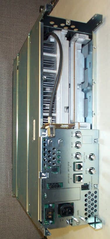
Click to zoom
Application Details
- Equipment Class
- TNB - Licensed Non-Broadcast Station Transmitter
- Date of Grant
- Oct 29, 2006
- Application Purpose
- Original Equipment
- Date of Application
- Oct 29, 2006
- Equipment Note
- Non-Broadcast Transmitter
- Frequency Range
- 435.00000000 - 512.00000000
- Company
- Motorola Solutions, Inc.
- Country
- United States
Documents & Files
Document Text
Text extracted from the exhibit documents filed with the FCC. Open a document above to read the original.
Users Manual
APPLICANT: MOTOROLA EQUIPMENT TYPE: ABZ89FC4819 EXHIBIT D User / Operational Manual Operational or User’s Manual The manual should include instruction, installation, operator, or technical manuals with required ‘information to the users’. This manual should include a statement that cautions the user that changes or modifications not expressly approved by the party responsible for compliance could void the user’s authority to operate the equipment. The manual shall include RF Hazard warning statements, if applicable. The instruction and service manual for this base radio are not published at this time. However, draft copy of some of the manual information has been assembled and has been included as part of this filing package. Upon request, published and/or printed manuals will be sent to the commission and/or telecommunication certification body (TCB) as soon as they become available. All of the descriptions, block diagrams, and schematics that are included in this filing package are current as of the package submittal date. EXHIBIT DESCRIPTION D1-1 Manual Front Matter (Draft) D1-2 Specifications (Draft) D1-3 Field Replaceable Units and Orderable Parts (Draft) D1-4 Tune-Up Procedure D1-5 Racking Configurations D1-6 Functional Description / Operation of Modules (Draft) APPLICANT: MOTOROLA EQUIPMENT TYPE: ABZ89FC4819 EXHIBIT D1-1 User / Operational Manual Manual Front Matter (Draft) APPLICANT: MOTOROLA EQUIPMENT TYPE: ABZ89FC4819 EXHIBIT D1-1 User / Operational Manual Manual Front Matter (Draft, Continued) APPLICANT: MOTOROLA EQUIPMENT TYPE: ABZ89FC4819 EXHIBIT D1-1 User / Operational Manual Manual Front Matter (Draft, Continued) APPLICANT: MOTOROLA EQUIPMENT TYPE: ABZ89FC4819 EXHIBIT D1-1 User / Operational Manual Manual Front Matter (Draft, Continued) APPLICANT: MOTOROLA EQUIPMENT TYPE: ABZ89FC4819 EXHIBIT D1-2 User / Operational Manual Specifications (Draft) General Performance ModelT7039 H x W x D5.25" x 19" x 18" (133x483x457mm) Weight45 lbs (20 kg) Power Requirements AC:90-264 VAC, 47-63 Hz DC:43-60 VDC Temperature Range-22 to 140F (-30 to 60C) Input / Output Impedance50 ohms Antenna Connectors Transmit:N female Receive:N female Modulation IV&D Transmit / Receive:C4FM, LSM Frequency StabilityExternal Reference Channel Spacing C4FM / LSM:12.5 kHz Transmitter Frequency Range435-524 MHz Power output C4FM:2-110 Watts LSM:2-110 Watts (Average) Electronic BandwidthFull Bandwidth Intermodulation Attenuation40 dB Spurious and Harmonic Emissions Attenuation90 dB FCC Type Acceptance FCC Designation:Frequency RangeTypePower Output ABZ89FC4819435-512 MHzTransmitter, C4FM/LSMVariable 2-110 W ABZ89FR4820435-512 MHzReceiverN/A APPLICANT: MOTOROLA EQUIPMENT TYPE: ABZ89FC4819 EXHIBIT D1-3 User / Operational Manual Field Replaceable Units and Orderable Parts (Draft) Field replaceable units, or FRUs, include special packaging to allow shipment to customers. Parts and FRUs available for customer order are listed in this section. All parts and FRUs are sourced through the Radio Products and Service Division (RPSD). FRU # Description DLN1347A FRU: PA Mid Power 435-524 MHz DLN6568A FRU: AC / 48V DC Power Supply DLN1327A FRU: Power Supply Fan Module DLN1346A FRU: Transceiver 435-524 MHz DLN6569A FRU: Site Controller DLN6636A FRU: Expansion HUB DLN1380A FRU: Cabinet RMC Pass Through Module DLN1375A FRU: 435-524 MHz Site LNA Module DLN1374A FRU: 435-524 MHz Cabinet LNA Module DLN1340A FRU: Receive Multi-Coupler Tray DLN1338A FRU: Fan Module DLN1329A FRU: Site Controller Backplane DLN1330A FRU: Base Radio Backplane DLN1343A FRU: Expandable Site Subsystem Backplane DLN1339A FRU: AC Power Distribution Module Customer Replaceable Power Cables for Standalone Base Radio Part Number Description TRN7663A Power Cable, North America TRN7755A Power Cable, Continental Europe TTN5049A Power Cable, UK / Ireland TTN5103A Power Cable, Australia Other Customer Replaceable Part Part Number Description 3084827Y01 Battery Temperature Sensor Extension Cable 6484850Y01 Junction Panel (Cabinet Mounting) 6485367Y01 Junction Panel (Rack Mounting) Other Misc. Hardware Part Number Description X153AW Rack Mount Hardware X182BZ Duplexer, UHF X676BG External Dual Circulator Tray UHF CA01130AA UHF Duplexer 435-470 MHz CA01120AA UHF Duplexer 470-494 MHz CA01119AA UHF Duplexer 494-512 MHz X265AK Base Radio Preselector 435-470 MHz X265AL Base Radio Preselector 470-512 MHz APPLICANT: MOTOROLA EQUIPMENT TYPE: ABZ89FC4819 EXHIBIT D1-3 APPLICANT: MOTOROLA EQUIPMENT TYPE: ABZ89FC4819 EXHIBIT D1-4 User / Operational Manual Tune-Up Procedure There is no field tune-up procedure. All adjustments are software controlled and are pre-set at the factory. Certain station operating parameters can be changed via man-machine interface (MMI) commands, within predetermined limits. Examples include transmit / receiver operating frequencies and transmitter power level. APPLICANT: MOTOROLA EQUIPMENT TYPE: ABZ89FC4819 EXHIBIT D1-5 User / Operational Manual Racking Configurations There are various equipment racking configurations available to customers. The following section includes sketches which depict many of the racking alternatives. GTR 8000 Expandable Site Sub-system Layout PS #1 PS #2PS #3PS #4 PS #5 PS #6 PA #1PA #2 PA #3 PA #4 PA #5PA #6 XCVR #1 XCVR #2 XCVR #3 XCVR #4XCVR #5XCVR #6 SC #1SC #2 ALARM Bay #1Bay #2 Bay #3 PS #1 PS #2PS #3PS #4 PS #5 PS #6 PA #1PA #2 PA #3 PA #4 PA #5PA #6 XCVR #1 XCVR #2 XCVR #3 XCVR #4XCVR #5XCVR #6 SC #1SC #2 ALARM Bay #1Bay #2 Bay #3 Fan Module #1 serves PA Bay #1 Fan Module #2 serves PA Bay #2 Fan Module #3 serves PA Bay #3 Fan Module #4 serves XCVR Bay #1 Fan Module #5 serves XCVR Bay #2 Fan Module #6 serves XCVR Bay #3 Fan Module #1 serves PA Bay #1 Fan Module #2 serves PA Bay #2 Fan Module #3 serves PA Bay #3 Fan Module #4 serves XCVR Bay #1 Fan Module #5 serves XCVR Bay #2 Fan Module #6 serves XCVR Bay #3 Configuration Layout PA XCVR PS Base Radio PA XCVR PS XCVR #2 PS XCVR #1 XCVR #2XCVR #2 PS Receive Only Base Radio…
Text truncated - open the document above for the full version.
External Photos
APPLICANT: MOTOROLA EQUIPMENT TYPE: ABZ89FC4819 EXHIBIT C Photographs of the Device Photographs – Index EXHIBIT DESCRIPTION C1-1 External Front View of Base Radio C1-2 External Front View of Base Radio, Front Panel Removed C1-3 External Front View, Alternate Racking of Base Radio in ‘GTR 8000 Expandable Site Sub-system’ C2-1 External Back View of Base Radio C2-2 FCC Identification Label C3-1.1 Internal Front View – Transceiver Module C3-1.2 Internal Front View – Transceiver Module, Circuit Board, Top View C3-1.3 Internal Front View – Transceiver Module, Control Section C3-1.4 Internal Front View – Transceiver Module, Exciter Section C3-1.5 Internal Front View – Transceiver Module, Receiver Section C3-2 Internal Front View – Power Amplifier Module, Cover Removed C3-3.1 Internal Front View – Power Supply Module C3-3.2 Internal Front View – Power Supply Module, Circuit Boards, Top View C3-4 Internal Front View – Backplane C4-1 Internal Back View – Transceiver Module C4-2 Internal Back View – Power Amplifier Module C4-3 Internal Back View – Power Supply Module, Circuit Boards, Back View C4-4 Internal Back View – Backplane APPLICANT: MOTOROLA EQUIPMENT TYPE: ABZ89FC4819 EXHIBIT C1-1 Photographs of the Device External Front View of Base Radio APPLICANT: MOTOROLA EQUIPMENT TYPE: ABZ89FC4819 EXHIBIT C1-2 Photographs of the Device External Front View of Base Radio, Front Panel Removed APPLICANT: MOTOROLA EQUIPMENT TYPE: ABZ89FC4819 EXHIBIT C1-3 Photographs of the Device External Front View of Base Radio, Alternate Racking of Base Radio in ‘GTR 8000 Expandable Site Sub-system’ Configuration APPLICANT: MOTOROLA EQUIPMENT TYPE: ABZ89FC4819 EXHIBIT C2-1 Photographs of the Device External Back View of Base Radio APPLICANT: MOTOROLA EQUIPMENT TYPE: ABZ89FC4819 EXHIBIT C2-2 Photographs of the Device FCC Identification Label APPLICANT: MOTOROLA EQUIPMENT TYPE: ABZ89FC4819 EXHIBIT C3-1.1 Photographs of the Device Internal Front View – Transceiver Module
ID Label/Location Info
APPLICANT: MOTOROLA EQUIPMENT TYPE: ABZ89FC4819 EXHIBIT A1 Equipment Label FCC Identification Number The FCC Identifier (FCC ID) is made up of the Grantee Code, supplied by the FCC, and an Equipment Product Code. This equipment product code may be to 14 characters in length, and is assigned by the grantee (applicant). The Grantee Code for this product is ABZ The Equipment Product Code for this product is 89FC4819 The entire FCC ID number is ABZ89FC4819 APPLICANT: MOTOROLA EQUIPMENT TYPE: ABZ89FC4819 EXHIBIT A2-1 Equipment Label FCC ID Label A representative image of the FCC Identification label is shown below. This label is generated as part of the standard manufacturing process and is printed in the factory. Much of the information that is on the label, such as serial number, model number, etc. is driven by the ordering process and is unique per customer order. FCC Identification Label APPLICANT: MOTOROLA EQUIPMENT TYPE: ABZ89FC4819 EXHIBIT A2-2 Equipment Label FCC ID Label The location of the FCC ID label is on the back of the radio, as shown in the photograph below. Location of FCC ID Label
Internal Photos
APPLICANT: MOTOROLA EQUIPMENT TYPE: ABZ89FC4819 EXHIBIT C3-1.2 Photographs of the Device Internal Front View – Transceiver Module Circuit Board Top View APPLICANT: MOTOROLA EQUIPMENT TYPE: ABZ89FC4819 EXHIBIT C3-1.3 Photographs of the Device Internal Front View – Transceiver Module, Control Section APPLICANT: MOTOROLA EQUIPMENT TYPE: ABZ89FC4819 EXHIBIT C3-1.4 Photographs of the Device Internal Front View – Transceiver Module, Exciter Section APPLICANT: MOTOROLA EQUIPMENT TYPE: ABZ89FC4819 EXHIBIT C3-1.5 Photographs of the Device Internal Front View – Transceiver Module, Receiver Section APPLICANT: MOTOROLA EQUIPMENT TYPE: ABZ89FC4819 EXHIBIT C3-2 Photographs of the Device Internal Front View – Power Amplifier Module, Cover Removed APPLICANT: MOTOROLA EQUIPMENT TYPE: ABZ89FC4819 EXHIBIT C3-3.1 Photographs of the Device Internal Front View – Power Supply Module APPLICANT: MOTOROLA EQUIPMENT TYPE: ABZ89FC4819 EXHIBIT C3-3.2 Photographs of the Device Internal Front View – Power Supply Module, Circuit Boards, Top View APPLICANT: MOTOROLA EQUIPMENT TYPE: ABZ89FC4819 EXHIBIT C3-4 Photographs of the Device Internal Front View – Backplane APPLICANT: MOTOROLA EQUIPMENT TYPE: ABZ89FC4819 EXHIBIT C4-1 Photographs of the Device Internal Back View – Transceiver Module APPLICANT: MOTOROLA EQUIPMENT TYPE: ABZ89FC4819 EXHIBIT C4-2 Photographs of the Device Internal Back View – Power Amplifier Module APPLICANT: MOTOROLA EQUIPMENT TYPE: ABZ89FC4819 EXHIBIT C4-3 Photographs of the Device Internal Back View – Power Supply Module, Circuit Boards, Back View APPLICANT: MOTOROLA EQUIPMENT TYPE: ABZ89FC4819 EXHIBIT C4-4 Photographs of the Device Internal Back View – Backplane
Parts List/Tune Up Info
APPLICANT: MOTOROLA EQUIPMENT TYPE: ABZ89FC4819 EXHIBIT D1-4 User / Operational Manual Tune-Up Procedure There is no field tune-up procedure. All adjustments are software controlled and are pre-set at the factory. Certain station operating parameters can be changed via man-machine interface (MMI) commands, within predetermined limits. Examples include transmit / receiver operating frequencies and transmitter power level.
Test Report
APPLICANT: MOTOROLA EQUIPMENT TYPE: ABZ89FC4819 EXHIBIT E Report on Test Measurements Measurements Report The measurement report shows compliance information against the pertinent technical standards. Each section of the report contains either verbiage or graphs which show compliance to applicable standards as required. Each section also explains testing method and indicates what the applicable specification is. A list of test equipment for all sections, and certification signoff page are included at the end of the measurement report. SUBMITTED MEASURED DATA -- INDEX EXHIBIT DESCRIPTION E1-1 RF Output-Data E1-2 Occupied Bandwidth: Setup, Specifications, and Index E1-2.1 Linear Simulcast Modulation (LSM), Low End of Band E1-2.2 Linear Simulcast Modulation (LSM), Middle of Band E1-2.3 Linear Simulcast Modulation (LSM), High End of Band E1-2.4 Compatible 4-Level Frequency Modulation (C4FM), Low End of Band E1-2.5 Compatible 4-Level Frequency Modulation (C4FM), Middle of Band E1-2.6 Compatible 4-Level Frequency Modulation (C4FM), High End of Band E1-3 Conducted Spurious Emissions: Setup, Specifications, and Index E1-3.1 LSM Conducted Spurious Emissions, Harmonics, Power 110 Watts, Low / Mid / High Frequencies E1-3.2 LSM Conducted Spurious Emissions, Harmonics, Power 2 Watts, Low / Mid / High Frequencies E1-3.3 C4FM Conducted Spurious Emissions, Harmonics, Power 110 Watts, Low / Mid / High Frequencies E1-3.4 C4FM Conducted Spurious Emissions, Harmonics, Power 2 Watts, Low / Mid / High Frequencies E1-3.5 Conducted Spurious Emissions, Close-In, 500 kHz Span, Power Output at 110 Watts, LSM E1-3.6 Conducted Spurious Emissions, Close-In, 5 MHz Span, Power Output at 110 Watts, LSM E1-3.7 Conducted Spurious Emissions, Close-In, 100 MHz Span, Power Output at 110 Watts, LSM E1-3.8 Conducted Spurious Emissions, Close-In, 500 kHz Span, Power Output at 110 Watts, C4FM E1-3.9 Conducted Spurious Emissions, Close-In, 5 MHz Span, Power Output at 110 Watts, C4FM E1-3.10 Conducted Spurious Emissions, Close-In, 100 MHz Span, Power Output at 110 Watts, C4FM E1-4 Radiated Spurious Emissions: Setup, Specifications, and Index E1-4.1 LSM Radiated Spurious Emissions, Harmonics, Power 110 Watts, Low / Mid / High Frequencies E1-4.2 LSM Radiated Spurious Emissions, Harmonics, Power 2 Watts, Low / Mid / High Frequencies E1-4.3 C4FM Radiated Spurious Emissions, Harmonics, Power 110 Watts, Low / Mid / High Frequencies E1-4.4 C4FM Radiated Spurious Emissions, Harmonics, Power 2 Watts, Low / Mid / High Frequencies APPLICANT: MOTOROLA EQUIPMENT TYPE: ABZ89FC4819 EXHIBIT E Report on Test Measurements Measurements Report SUBMITTED MEASURED DATA – INDEX (Continued) EXHIBIT DESCRIPTION E1-5 Frequency Stability: Setup, Specifications, and Index E1-5.1 Frequency Stability Vs Temperature E1-5.2 Frequency Stability Vs Voltage E1-6 Frequency Transient Behavior: Setup, Specifications, Index E1-6.1 Frequency Transient Behavior, 12.5 kHz Channel Key-Up, Low End of Band E1-6.2 Frequency Transient Behavior, 12.5 kHz Channel Key-Up, Middle of Band E1-6.3 Frequency Transient Behavior, 12.5 kHz Channel Key-Up, High End of Band E1-6.4 Frequency Transient Behavior, 12.5 kHz Channel De-key, Low End of Band E1-6.5 Frequency Transient Behavior, 12.5 kHz Channel De-key, Middle of Band E1-6.6 Frequency Transient Behavior, 12.5 kHz Channel De-key, High End of Band E1-11 Test Equipment Used E1-12 Statement of Certification APPLICANT: MOTOROLA EQUIPMENT TYPE: ABZ89FC4819 EXHIBIT E1-1 Report on Test Measurements RF Power Output Data The RF power output was measured with the indicated voltage applied to and current into the final RF amplifying device. The DC current indicated is the total for the final RF amplifier stage, consisting of four parallel power transistors. Linear Simulcast Modulation Mode: Measured RF output 110 Watts, Average DC Voltage 28.5 Volts DC Current 12.3 Amperes Input power for final RF amplifying device(s) 350 Watts Primary Radio Input Supply Voltage 120 Volts AC Minimum Measured RF output 2 Watts, Average Normal DC Voltage 21.0 Volts Normal DC Current 3.0 Amperes Input power for final RF amplifying device(s) 63 Watts Primary Radio Input Supply Voltage 120 Volts AC Compatible 4-Level Frequency Modulation Mode: Measured RF output 110 Watts DC Voltage 21.0 Volts DC Current 13.7 Amperes Input power for final RF amplifying device(s) 290 Watts Primary Radio Input Supply Voltage 120 Volts AC Minimum Measured RF output 2 Watts Normal DC Voltage 21.0 Volts Normal DC Current 3.0 Amperes Input power for final RF amplifying device(s) 63 Watts Primary Radio Input Supply Voltage 120 Volts AC APPLICANT: MOTOROLA EQUIPMENT TYPE: ABZ89FC4819 EXHIBIT E1-2 Report on Test Measurements Occupied Bandwidth – Linear Simulcast Modulation (LSM), 12.5 kHz Channel Spacing There is one exhibit shown for Linear Simulcast Modulation. It can be used in a system configuration based upon channel usage as described in Exhibit B. The occupied bandwidth chart references the following setup and specification requirements. Modulation Type: Linear Simulcast Modulation, LSM Emission Designator: 8K70D1W Channelization: 12.5 kHz Power Setting: 110 Watts, Average Specification Requirement § 90.210(d) Emission Limits: Emission Mask D. For transmitters designed to operate with a 12.5 kHz channel bandwidth, any emission must be attenuated below the power (P) of the highest emission contained within the authorized bandwidth as follows: (1) On any frequency from the center of the authorized bandwidth (f 0 ) to 5.625 kHz removed from f 0 : Zero dB (2) On any frequency removed from the center of the authorized bandwidth by a displacement frequency (f d in kHz) of more than 5.625 kHz but no more than 12.5 kHz: At least 7.27 *( f d –2.88 kHz) dB (3) On any frequency removed from the center of the authorized bandwidth by a displacement frequency (f d in kHz) of more than 12.5 kHz: At least 50 plus 10 log 10 (P) dB or 70 dB, whichever is the lesser attenuation. (4) The reference level…
Text truncated - open the document above for the full version.
Contact Information
Applicant
Matthew Nawrocki
Technical Specifications
| # | Rule Parts | Frequency Range | Power Output | Emission | Tolerance |
|---|---|---|---|---|---|
| 2 | 9 | 435 MHz - 512 MHz | 110 W | 8K10F1E | 1.5 ppm |
Other Applications from Motorola Solutions, Inc.

ABZ89FT4940
Aug 06, 2026Non Broadcast Transmitter
Equipment Class
TNB - Licensed Non-Broadcast Station TransmitterABZ89FT4950
Jun 25, 2026Non-Broadcast Transmitter
Equipment Class
TNB - Licensed Non-Broadcast Station TransmitterABZ89FT5901
Jun 20, 2024Non Broadcast Transmitter
Equipment Class
TNB - Licensed Non-Broadcast Station Transmitter
ABZ99FT5101B
May 02, 2023Non Broadcast Transmitter
Equipment Class
PCB - PCS Licensed Transmitter
ABZ99FT3095B
Mar 26, 2023Non Broadcast Transmitter
Equipment Class
TNB - Licensed Non-Broadcast Station Transmitter