ABZ89FC4827Non Broadcast Transmitter
Motorola Solutions, Inc.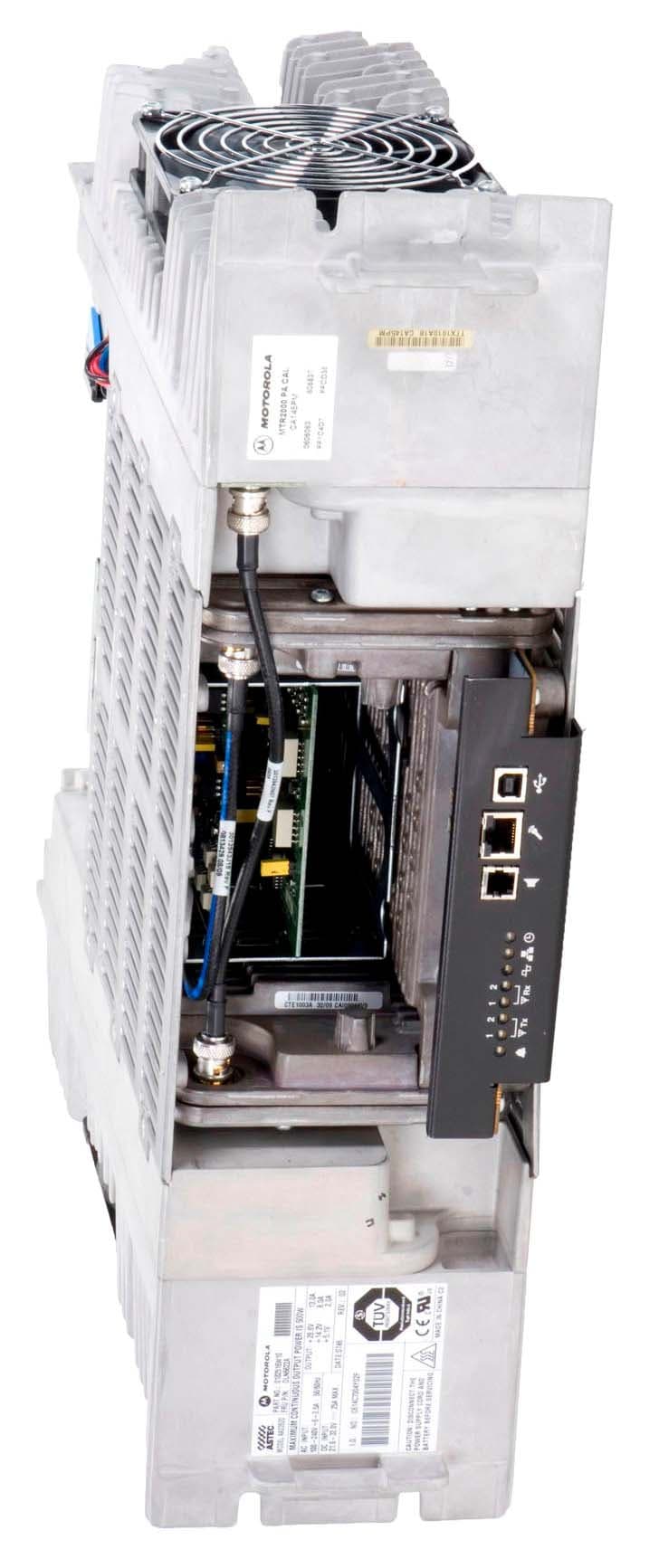
Click to zoom
Application Details
- Equipment Class
- TNB - Licensed Non-Broadcast Station Transmitter
- Date of Grant
- Jan 17, 2010
- Application Purpose
- Original Equipment
- Date of Application
- Jan 17, 2010
- Equipment Note
- Non Broadcast Transmitter
- Frequency Range
- 406.10000000 - 470.00000000
- Company
- Motorola Solutions, Inc.
- Country
- United States
Documents & Files
Document Text
Text extracted from the exhibit documents filed with the FCC. Open a document above to read the original.
Users Manual
APPLICANT: MOTOROLA EQUIPMENT TYPE: ABZ89FC4827 EXHIBIT D User / Operational Manual Operational or User’s Manual The manual should include instruction, installation, operator, or technical manuals with required ‘information to the users’. This manual should include a statement that cautions the user that changes or modifications not expressly approved by the party responsible for compliance could void the user’s authority to operate the equipment. The manual shall include RF Hazard warning statements, if applicable. The instruction and service manual for this base radio are not published at this time. However, draft copy of available manual information has been assembled and has been included as part of this filing package. Upon request, published manuals will be sent to the commission and/or telecommunication certification body (TCB) as soon as they become available. All of the descriptions, block diagrams, and schematics that are included in this filing package are current as of the package submittal date. EXHIBIT DESCRIPTION D1-1 Manual Front Matter (Draft) D1-2 Specifications (Draft) D1-3 Field Replaceable Units and Orderable Parts (Draft) D1-4 Tune-Up Procedure (Draft) D1-5 Racking Configurations (Draft) D1-6 Functional Description / Operation of Modules (Draft) APPLICANT: MOTOROLA EQUIPMENT TYPE: ABZ89FC4827 EXHIBIT D1-1 User / Operational Manual Manual Front Matter (Draft) APPLICANT: MOTOROLA EQUIPMENT TYPE: ABZ89FC4827 EXHIBIT D1-1 User / Operational Manual Manual Front Matter (Draft, Continued) APPLICANT: MOTOROLA EQUIPMENT TYPE: ABZ89FC4827 EXHIBIT D1-1 User / Operational Manual Manual Front Matter (Draft, Continued) APPLICANT: MOTOROLA EQUIPMENT TYPE: ABZ89FC4827 EXHIBIT D1-1 User / Operational Manual Manual Front Matter (Draft, Continued) APPLICANT: MOTOROLA EQUIPMENT TYPE: ABZ89FC4827 EXHIBIT D1-2 User / Operational Manual Specifications (Draft) General Performance ModelT2003 Number of Channels16 Frequency GenerationSynthesized H x W x D5.25" x 19" x 16.5" (133x483x419mm) Weight40 lbs (19 kg) Power Requirements AC: 85-264 VAC, 47-63 HzStandy 0.6A, Rated Power 5.4A @ 117 VAC DC: 21.6 - 32 Volts DCStandy 1A, Rated Power 13A @ 28 VDC Temperature Range-30 to 60 °C (-22 to 140 °F) Input / Output Impedance50 ohms Antenna Connectors Tx / RxN-Type Modes of OperationHalf-Duplex / Duplex Frequency Bands403 - 470 MHz Internal Frequency Stability1.5 PPM External Reference CapableYes Channel Spacing12.5 kHz, 25 kHz Transmitter Frequency Range406.1-470 MHz Rated Output Power25 - 100 Watts, Variable Intermodulation Attenuation40 dB Adjacent Channel Power -80 dBc (25 kHz) / -60 dBc (12.5 kHz) Wideband Noise (1 MHz)-152 dBc/Hz Rated System Deviation5 kHz (25 kHz) / 2.5 kHz (12.5 kHz) Audio Distortion<3% FM Hum and Noise50 dB (25 kHz) / 45 dB (12.5 kHz) Spurious Harmonic Emissions Attenuation 85 dB FCC Type Acceptance FCC Identifier:Frequency RangeTypePower Output ABZ89FC4827406.1-470 MHzTransmitterVariable 25-100 W ABZ89FR4828406.1-470 MHzReceiverN/A APPLICANT: MOTOROLA EQUIPMENT TYPE: ABZ89FC4827 EXHIBIT D1-3 User / Operational Manual Field Replaceable Units and Orderable Parts (Draft) Motorola provides the following approved accessories to improve the productivity of your base station / repeater. For a list of Motorola-approved accessories, visit the following web site: http://www.motorola.com/governmentandenterprise . MOTOTRBO MTR3000 Ordering Guideline Model Description T3000 MTR3000 Base Station/Repeater X340MT UHF 100W Power (403–470 MHz) X540MT UHF 100W Power (470–524 MHz) X182UL Duplexer, UHF 403–435 MHz X182UM Duplexer, UHF 435–470 MHz X182UN Duplexer, UHF 470–494 MHz X182UH Duplexer, UHF 494–512 MHz X265UL Preselector, UHF 380–435 MHz X265UM Preselector, UHF 435–470 MHz X265UH Preselector, UHF 470–524 MHz X676UL Dual Circulator, UHF (403–470 MHz) X676UH Dual Circulator, UHF (470–524 MHz) X371BA Antenna Relay Note: Antenna Relay is not compatible if ordering X182, Duplexer X189AA Power Cable, Europe X162AD Power Cable, UK X191AD Power Cable, Australia CA01520AA Power Cable, DC U178AB Cabinet Mount Hardware X153BA Rack Mount Hardware X347AF Manual Install and User CD X244AF Auxiliary System Cable X244AG Community Base Station/Repeater Panel Cable X244AH Phone Patch Cable C540AD System Connector Cable XA00032AA 12 inch Ethernet Cable CLN8665A 6 feet High speed USB cable HKLN4439_ MTR3000 Capacity Plus Software Upgrade Customer Replaceable Power Cables for Standalone Base Radio Part Number Description TRN7663A Power Cable, North America TRN7755A Power Cable, Continental Europe TTN5049A Power Cable, UK / Ireland TTN5103A Power Cable, Australia APPLICANT: MOTOROLA EQUIPMENT TYPE: ABZ89FC4827 EXHIBIT D1-3 User / Operational Manual Field Replaceable Units and Orderable Parts (Draft) (Continued) MOTOTRBO MTR3000 Field Replaceable Units Model Description DLN6701_ 100W PA, UHF 403–470 MHz DLN6702_ 100W PA, UHF 470–524 MHz DLN6703_ Exciter, UHF 403–470 MHz DLN6704_ Exciter, UHF 450–524 MHz DLN6705_ Receiver, UHF 403–470 MHz DLN6706_ Receiver, UHF 450–524 MHz DLN6707_ AC/DC Power Supply DLN6719_ Station Control TCXO CLN8629 MOTOTRBO MTR3000 Installation and User CD X347AF Manual Install and User CD Note The Manual Install and User CD contains: • MOTOTRBO MTR3000 Installation and User Manual (Including MTR2000 to MTR3000 MOTOTRBO Upgrade Kit) • MOTOTRBO MTR3000 Basic Service Manual Microphones/Speakers Model Description GMMN4063 Noise Cancelling Mic 0185180U01 Cable For External Speaker HSN1006 Speaker Miscellaneous Accessories Model Description RRX4025 ISB50LNC2 Bulkhead Arrestor 125-100 RRX4032 T-1 ISB50 Series Round Member Mount RRX4021 Lightening / Surge Arrestor RRX4034 Lightening / Surge Arrestor (110/220V AC Line Surge Protector) TRN4589 Dual Line Suppressor 3083908X02 Cable, Field System Adapter CLN1317* Antenna Relay CLN1316** Antenna Relay For Preselector Note (*) Includes Antenna Relay and required cables for stations without X265, Preselector (**) Includes Antenna Relay and required …
Text truncated - open the document above for the full version.
External Photos
APPLICANT: MOTOROLA EQUIPMENT TYPE: ABZ89FC4827 EXHIBIT C Photographs of the Device Photographs – Index EXHIBIT DESCRIPTION C1-1 External Front View of Base Radio C1-2 External Front View of Base Radio, Front Panel Removed C2-1 External Back View of Base Radio C2-2 FCC Identification Label C3-1 Internal Front View – Receiver, Exciter, and Control Modules (“Cluster”) C3-2.1 Internal Front View – Control Module with Housing, Top View C3-2.2 Internal Front View – Control Board, Top View C3-3 Internal Front View – Exciter Board, Top View C3-4 Internal Front View – Receiver Board, Top View C3-5.1 Internal Front View – Power Amplifier Module C3-5.2 Internal Front View – Power Amplifier Module, Cover Removed C3-6 Internal Front View – Power Supply Module C3-7 Internal Front View – Backplane C4-1 Internal Back View – Receiver, Exciter, and Control Modules (“Cluster”), Disassembled C4-2 Internal Back View – Control Board, Bottom View C4-3 Internal Back View – Exciter Board, Bottom View C4-4 Internal Back View – Receiver Board, Bottom View C4-5 Internal Back View – Power Amplifier Module C4-6 Internal Back View – Power Supply Module C4-7 Internal Back View – Backplane APPLICANT: MOTOROLA EQUIPMENT TYPE: ABZ89FC4827 EXHIBIT C1-1 Photographs of the Device External Front View of Base Radio APPLICANT: MOTOROLA EQUIPMENT TYPE: ABZ89FC4827 EXHIBIT C1-2 Photographs of the Device External Front View of Base Radio, Front Panel Removed APPLICANT: MOTOROLA EQUIPMENT TYPE: ABZ89FC4827 EXHIBIT C2-1 Photographs of the Device External Back View of Base Radio
ID Label/Location Info
APPLICANT: MOTOROLA EQUIPMENT TYPE: ABZ89FC4827 EXHIBIT A1 Equipment Label FCC Identification Number The FCC Identifier (FCC ID) is made up of the Grantee Code, supplied by the FCC, and an Equipment Product Code. This equipment product code may be to 14 characters in length, and is assigned by the grantee (applicant). The Grantee Code for this product is ABZ The Equipment Product Code for this product is 89FC4827 The entire FCC ID number is ABZ89FC4827 APPLICANT: MOTOROLA EQUIPMENT TYPE: ABZ89FC4827 EXHIBIT A2-1 Equipment Label FCC ID Label A representative image of the FCC Identification label is shown below. This label is generated as part of the standard manufacturing process and is printed in the factory. Much of the information that is on the label, such as serial number, model number, etc. is driven by the ordering process and is unique per customer order. Serial No: 512ABC6789 F.O. No: 1212-3434-62789 Page No: 1 Item No: 2 Model Number: T2003A TX FCC ID: ABZ89FC4827 RX FCC ID: ABZ89FR4828 IC: 109AB-T2003 T2003-UHF AC Rating: 120 - 240V ~ Max 7A 50/60 Hz DC Rating: 28.6V 21A Professional Transceiver 5N 77 FCC Identification Label APPLICANT: MOTOROLA EQUIPMENT TYPE: ABZ89FC4827 EXHIBIT A2-2 Equipment Label FCC ID Label The location of the FCC ID label is on the back of the radio, as shown in the photograph below. Location of FCC ID Label
Internal Photos
APPLICANT: MOTOROLA EQUIPMENT TYPE: ABZ89FC4827 EXHIBIT C3-1 Photographs of the Device Internal Front View –Receiver, Exciter, and Control Modules (“Cluster”) APPLICANT: MOTOROLA EQUIPMENT TYPE: ABZ89FC4827 EXHIBIT C3-2.1 Photographs of the Device Internal Front View – Control Module with Housing, Top View APPLICANT: MOTOROLA EQUIPMENT TYPE: ABZ89FC4827 EXHIBIT C3-2.2 Photographs of the Device Internal Front View – Control Board, Top View APPLICANT: MOTOROLA EQUIPMENT TYPE: ABZ89FC4827 EXHIBIT C3-3 Photographs of the Device Internal Front View – Exciter Board, Top View APPLICANT: MOTOROLA EQUIPMENT TYPE: ABZ89FC4827 EXHIBIT C3-4 Photographs of the Device Internal Front View –Receiver Board, Top View APPLICANT: MOTOROLA EQUIPMENT TYPE: ABZ89FC4827 EXHIBIT C3-5.1 Photographs of the Device Internal Front View – Power Amplifier Module APPLICANT: MOTOROLA EQUIPMENT TYPE: ABZ89FC4827 EXHIBIT C3-5.2 Photographs of the Device Internal Front View – Power Amplifier Module, Cover Removed APPLICANT: MOTOROLA EQUIPMENT TYPE: ABZ89FC4827 EXHIBIT C3-6 Photographs of the Device Internal Front View – Power Supply Module APPLICANT: MOTOROLA EQUIPMENT TYPE: ABZ89FC4827 EXHIBIT C3-7 Photographs of the Device Internal Front View – Backplane APPLICANT: MOTOROLA EQUIPMENT TYPE: ABZ89FC4827 EXHIBIT C4-1 Photographs of the Device Internal Back View – Upgrade Kit - Receiver, Exciter, Control Modules (“Cluster”), Disassembled APPLICANT: MOTOROLA EQUIPMENT TYPE: ABZ89FC4827 EXHIBIT C4-2 Photographs of the Device Internal Back View – Control Board, Bottom View APPLICANT: MOTOROLA EQUIPMENT TYPE: ABZ89FC4827 EXHIBIT C4-3 Photographs of the Device Internal Back View – Exciter Board, Bottom View APPLICANT: MOTOROLA EQUIPMENT TYPE: ABZ89FC4827 EXHIBIT C4-4 Photographs of the Device Internal Back View – Receiver Board, Bottom View APPLICANT: MOTOROLA EQUIPMENT TYPE: ABZ89FC4827 EXHIBIT C4-5 Photographs of the Device Internal Back View – Power Amplifier Module APPLICANT: MOTOROLA EQUIPMENT TYPE: ABZ89FC4827 EXHIBIT C4-6 Photographs of the Device Internal Back View – Power Supply Module APPLICANT: MOTOROLA EQUIPMENT TYPE: ABZ89FC4827 EXHIBIT C4-7 Photographs of the Device Internal Back View – Backplane
Parts List/Tune Up Info
APPLICANT: MOTOROLA EQUIPMENT TYPE: ABZ89FC4827 EXHIBIT D1-4 User / Operational Manual Tune-Up Procedure (Draft) See the following manual excerpts (Chapter 9 and Chapter 12 of MOTOTRBO MTR3000 Base Station / Repeater, Basic Service Manual) for instruction on performing the field digital upgrade, operational verification, and programming / tuning. Adjustments are software controlled and are pre-set at the factory. Certain station operating parameters can be changed using Customer Programming Software (CPS), within predetermined limits. Examples include transmit / receiver operating frequencies and transmitter power level. After the base station / repeater and ancillary equipment have been mechanically installed, properly cabled, and power applied, the equipment must then be optimized; that is, before placing the base station / repeater in operation. The cable required is a standard “USB A to B” cable. Optimization is performed through the Customer Programming Software (CPS), kit number RVN5115. After the base station / repeater is operational, the base station / repeater’s codeplug data must be copied to a PC- compatible computer. Optimization involves the following tasks: 1. Reading the base station / repeater codeplug from the base station / repeater (this ensures a match between the base station / repeater serial number (resident in the codeplug) and the serial number (part of the customized base station / repeater codeplug data) that is written back to the base station / repeater (see task 5). 2. Customizing the base station / repeater codeplug and saving the data to the base station / repeater. 3. Aligning the base station / repeater for: - Modulation Limit - Speaker Level - Station Reference - MTR2000 PA Calibration - Receiver Squelch Adjust 4. Performing post-optimization procedures. 5. Writing the customized codeplug to the base station / repeater codeplug. For details on these tasks, refer to the Customer Programming Software (CPS) Online Help.
Test Report
APPLICANT: MOTOROLA EQUIPMENT TYPE: ABZ89FC4827 EXHIBIT E Report on Test Measurements Measurements Report The measurement report shows compliance information against the pertinent technical standards. Each section of the report contains either verbiage or graphs which show compliance to applicable standards as required. Each section also explains testing method and indicates what the applicable specification is. A list of test equipment for all sections, and certification signoff page are included at the end of the measurement report. SUBMITTED MEASURED DATA – INDEX EXHIBIT DESCRIPTION E1-1 RF Output-Data E1-2 Audio Frequency Response – Modulation Characteristics: Setup, Specifications, Index E1-2.1 Audio Frequency Response – Modulation Characteristics, 25 kHz Channels E1-2.2 Audio Frequency Response – Modulation Characteristics, 12.5 kHz Channels E1-3 Audio Modulation Limiting – Modulation Characteristics: Setup, Specifications, Index E1-3.1 Audio Modulation Limiting – Modulation Characteristics, 25 kHz Channels E1-3.2 Audio Modulation Limiting – Modulation Characteristics, 12.5 kHz Channels E1-4 Occupied Bandwidth: Setup, Specifications, and Index Measurements for 25 kHz Channels: E1-4.1 Carrier with 2500 Hz Audio Tone E1-4.2 Carrier with 2500 Hz Audio Tone and Private Line (PL) Signaling E1-4.3 Carrier with 2500 Hz Audio Tone and Digital Private Line (DPL) Signaling Measurements for 12.5 kHz Channels: E1-4.11 Carrier with 2500 Hz Audio Tone E1-4.12 Carrier with 2500 Hz Audio Tone and Private Line (PL) Signaling E1-4.13 Carrier with 2500 Hz Audio Tone and Digital Private Line (DPL) Signaling E1-4.14 Carrier with Digitized Voice / Data APPLICANT: MOTOROLA EQUIPMENT TYPE: ABZ89FC4827 EXHIBIT E Report on Test Measurements Measurements Report SUBMITTED MEASURED DATA – INDEX (Continued) EXHIBIT DESCRIPTION E1-5 Conducted Spurious Emissions: Setup, Specifications, and Index E1-5.1 Conducted Spurious Emissions, Harmonics, Power 100 Watts, Low / Mid / High Frequencies E1-5.2 Conducted Spurious Emissions, Harmonics, Power 25 Watts, Low / Mid / High Frequencies E1-5.3 Conducted Spurious Emissions, Close-In, 200 MHz Span, Power Output at 100 Watts E1-5.4 Conducted Spurious Emissions, Close-In, 20 MHz Span, Power Output at 100 Watts E1-6 Radiated Spurious Emissions: Setup, Specifications, and Index E1-6.1 Radiated Spurious Emissions, Harmonics, Power 100 Watts, Middle of Band E1-6.2 Radiated Spurious Emissions, Harmonics, Power 25 Watts, Middle of Band E1-7 Frequency Stability: Setup, Specifications, and Index E1-7.1 Frequency Stability Vs Temperature E1-7.2 Frequency Stability Vs Voltage E1-8 Frequency Transient Behavior: Setup, Specifications, Index E1-8.1 Frequency Transient Behavior, 25 kHz Channel Key-Up E1-8.2 Frequency Transient Behavior, 25 kHz Channel De-key E1-8.3 Frequency Transient Behavior, 12.5 kHz Channel Key-Up E1-8.4 Frequency Transient Behavior, 12.5 kHz Channel De-key E1-11 Test Equipment Used E1-12 Statement of Certification APPLICANT: MOTOROLA EQUIPMENT TYPE: ABZ89FC4827 EXHIBIT E1-1 Report on Test Measurements RF Power Output Data The RF power output was measured with the indicated voltage applied to and current into the final RF amplifying device. The DC current indicated is the total for the final RF amplifier stage, consisting of four parallel power transistors. Analog Voice Frequency Modulation Mode: Measured RF output 100 Watts DC Voltage 28.6 Volts DC Current 9.15 Amperes Input power for final RF amplifying device(s) 260 Watts Primary Radio Input Supply Voltage 120 Volts AC Minimum Measured RF output 25 Watts, Average Normal DC Voltage 28.6 Volts Normal DC Current 4.5 Amperes Input power for final RF amplifying device(s) 130 Watts Primary Radio Input Supply Voltage 120 Volts AC Digital 4-Level Frequency Shift Key Modulation Mode: Measured RF output 100 Watts DC Voltage 28.6 Volts DC Current 9.15 Amperes Input power for final RF amplifying device(s) 260 Watts Primary Radio Input Supply Voltage 120 Volts AC Minimum Measured RF output 25 Watts, Average Normal DC Voltage 28.6 Volts Normal DC Current 4.5 Amperes Input power for final RF amplifying device(s) 130 Watts Primary Radio Input Supply Voltage 120 Volts AC APPLICANT: MOTOROLA EQUIPMENT TYPE: ABZ89FC4827 EXHIBIT E1-2 Report on Test Measurements Audio Frequency Response Specification Requirement per TIA 603: Audio Frequency Response, 25 kHz Channels: The audio frequency response from 300 Hz to 3000 Hz shall not vary more than +1 dB or -3 dB from a true 6 dB per octave pre-emphasis characteristic as referenced to the 1000 Hz level, with an additional 6 dB per octave attenuation allowed from 500 Hz to 300 Hz, and an additional 6 dB per octave attenuation is allowed from 2500 Hz to 3000 Hz in equipment operating in the 25 MHz to 869 MHz range. Audio Frequency Response, 12.5 kHz Channels: The audio frequency response from 300 Hz to 3000 Hz shall not vary more than +1 dB or -3 dB from a true 6 dB per octave pre-emphasis characteristic as referenced to the 1000 Hz level, with an additional 6 dB per octave attenuation allowed from 500 Hz to 300 Hz. An additional 6 dB per octave rolloff is allowed from 2300 Hz to 2700 Hz, and an additional 12 dB per octave is allowed from 2700 Hz to 3000 Hz in equipment operating in the 896 MHz to 940 MHz range or for 12.5 kHz channel operation. Modulation: Audio Test Tone Carrier Frequency: A carrier at 436.0125 MHz was measured. This frequency is near the center of the operating band 403-470 MHz EXHIBIT DESCRIPTION E1-2.1 Audio Frequency Response – Modulation Characteristics, 25 kHz Channels E1-2.2 Audio Frequency Response – Modulation Characteristics, 12.5 kHz Channels The specification limit is shown on the response plots APPLICANT: MOTOROLA EQUIPMENT TYPE: ABZ89FC4827 EXHIBIT E1-2.1 -50.0-40.0-30.0-20.0-10.0 0.0 10.020.0 100 1000 10000 AUDIO FREQUENCY IN HERTZ MODULATION LEVEL IN DECIBELS 6 dB / Octave +1 / -3 dB MOTOROLA, INC.TRANSMITTER AUDIO RESPONSE CHARACTERISTIC MODULATION LEVEL VS.…
Text truncated - open the document above for the full version.
Contact Information
Applicant
Matthew Nawrocki
Non-Technical Contact
Motorola, Inc.Ali Sajanlal
[email protected]847-576-2253
Technical Specifications
| # | Rule Parts | Frequency Range | Power Output | Emission | Tolerance |
|---|---|---|---|---|---|
| 4 | 9 | 406.1 MHz - 470 MHz | 100 W | 7K60FXD | 1.5 ppm |
Other Applications from Motorola Solutions, Inc.

ABZ89FT4940
Aug 06, 2026Non Broadcast Transmitter
Equipment Class
TNB - Licensed Non-Broadcast Station TransmitterABZ89FT4950
Jun 25, 2026Non-Broadcast Transmitter
Equipment Class
TNB - Licensed Non-Broadcast Station TransmitterABZ89FT5901
Jun 20, 2024Non Broadcast Transmitter
Equipment Class
TNB - Licensed Non-Broadcast Station Transmitter
ABZ99FT5101B
May 02, 2023Non Broadcast Transmitter
Equipment Class
PCB - PCS Licensed Transmitter
ABZ99FT3095B
Mar 26, 2023Non Broadcast Transmitter
Equipment Class
TNB - Licensed Non-Broadcast Station Transmitter