ABZ89FC4831Non Broadcast Transmitter
Motorola Solutions, Inc.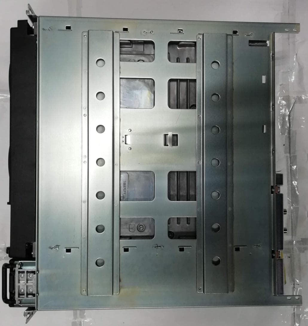
Click to zoom
Application Details
- Equipment Class
- TNB - Licensed Non-Broadcast Station Transmitter
- Date of Grant
- Feb 24, 2021
- Application Purpose
- Original Equipment
- Date of Application
- Feb 24, 2021
- Equipment Note
- Non Broadcast Transmitter
- Frequency Range
- 406.10000000 - 435.00000000
- Company
- Motorola Solutions, Inc.
- Country
- United States
Documents & Files
Document Text
Text extracted from the exhibit documents filed with the FCC. Open a document above to read the original.
Users Manual
GTR 8000 Base Radio ASTRO ® 25 INTEGRATED VOICE AND DATA *MN003286A01* MN003286A01-H JULY 2020 © 2020 Motorola Solutions, Inc. All rights reserved Declaration of Conformity Declaration of Conformity Per FCC CFR 47 Part 2 Section 2.1077(a) Responsible Party Name: Motorola Solutions, Inc. Address: 2000 Progress Pkwy, Schaumburg, IL 60196, U.S.A. Phone Number: 1-800-927-2744 Hereby declares that the product: GTR 8000 conforms to the following regulations: FCC Part 15, subpart B, section 15.107(a), 15.107(d), and section 15.109(a) Class A Digital Device This device complies with Part 15 of the FCC. Note: This equipment has been tested and found to comply with the limits for a Class A digital de- vice, pursuant to part 15 of the FCC Rules. These limits are designed to provide reasonable protec- tion against harmful interference when the equipment is operated in a commercial environment. This equipment generates, uses, and can radiate radio frequency energy and, if not installed and used in accordance with the instruction manual, may cause harmful interference to radio communi- cations. Operation of this equipment in a residential area is likely to cause harmful interference in which case the user will be required to correct the interference at his own expense. Notice to Users (FCC) This device complies with Part 15 of the FCC rules per the following conditions: • This device may not cause harmful interference. • This device must accept any interference received, including interference that may cause unde- sired operation. • Changes or modifications made to this device, not expressly approved by Motorola Solutions, could void the authority of the user to operate this equipment. MN003286A01-H Declaration of Conformity 2 Copyrights The Motorola Solutions products described in this document may include copyrighted Motorola Solutions computer programs. Laws in the United States and other countries preserve for Motorola Solutions certain exclusive rights for copyrighted computer programs. Accordingly, any copyrighted Motorola Solutions computer programs contained in the Motorola Solutions products described in this document may not be copied or reproduced in any manner without the express written permission of Motorola Solutions. © 2020 Motorola Solutions, Inc. All Rights Reserved No part of this document may be reproduced, transmitted, stored in a retrieval system, or translated into any language or computer language, in any form or by any means, without the prior written permission of Motorola Solutions, Inc. Furthermore, the purchase of Motorola Solutions products shall not be deemed to grant either directly or by implication, estoppel or otherwise, any license under the copyrights, patents or patent applications of Motorola Solutions, except for the normal non-exclusive, royalty-free license to use that arises by operation of law in the sale of a product. Disclaimer Please note that certain features, facilities, and capabilities described in this document may not be applicable to or licensed for use on a particular system, or may be dependent upon the characteristics of a particular mobile subscriber unit or configuration of certain parameters. Please refer to your Motorola Solutions contact for further information. Trademarks MOTOROLA, MOTO, MOTOROLA SOLUTIONS, and the Stylized M Logo are trademarks or registered trademarks of Motorola Trademark Holdings, LLC and are used under license. All other trademarks are the property of their respective owners. European Union (EU) Waste of Electrical and Electronic Equipment (WEEE) directive The European Union's WEEE directive requires that products sold into EU countries must have the crossed out trash bin label on the product (or the package in some cases). As defined by the WEEE directive, this cross-out trash bin label means that customers and end-users in EU countries should not dispose of electronic and electrical equipment or accessories in household waste. Customers or end-users in EU countries should contact their local equipment supplier representative or service centre for information about the waste collection system in their country. MN003286A01-H Copyrights 3 Contact Us The Solutions Support Center (SSC) is the primary contact for technical support included in your organization's service agreement with Motorola Solutions. Service agreement customers should be sure to call the SSC in all situations listed under Customer Responsibilities in their agreement, such as: • Before reloading software • To confirm troubleshooting results and analysis before taking action Your organization received support phone numbers and other contact information appropriate for your geographic region and service agreement. Use that contact information for the most efficient response. However, if needed, you can also find general support contact information on the Motorola Solutions website, by following these steps: 1Enter motorolasolutions.com in your browser. 2Ensure that your organization's country or region is displayed on the page. Clicking or tapping the name of the region provides a way to change it. 3Select "Support" on the motorolasolutions.com page. Comments Send questions and comments regarding user documentation to [email protected]. Provide the following information when reporting a documentation error: • The document title and part number • The page number or title of the section with the error • A description of the error Motorola Solutions offers various courses designed to assist in learning about the system. For information, go to https://learning.motorolasolutions.com to view the current course offerings and technology paths. MN003286A01-H Contact Us 4 Document History VersionDescriptionDate MN003286A01-AOriginal release of the GTR 8000 Base Radio manual November 2016 MN003286A01-BUpdated the following sections: • CSS Initial Device Configuration on page 135 • GTR 8000 Base Radio General Troubleshoot- ing on page 213 November …
Text truncated - open the document above for the full version.
Attestation Statements
Certification Department Elite Electronic Engineering Inc. 1516 Centre Circle Downers Grove, IL 60515 Date: November 2 nd , 2020 Subject: Application Authorization for FCC and IC Filing To whom it may concern, I hereby authorize Arine Lee to apply, on my behalf, the application for the following FCC and IC filing: FCC ID: ABZ89FC4831 IC ID: 109AB-4831 IC HVIN: GTR8000-UHF130W Please contact me if there are any questions or issues. Regards, Robert Sarocka Engineering Manager 847-344-6075 [email protected]
Cover Letter(s)
FCC ID: ABZ89FC4831 ___________________________________________________________________________________________________________ Motorola Solutions Malaysia Sdn Bhd, Plot2A, Medan Bayan Lepas, Mukim 12 SWD, 11900 Penang, Malaysia EXHIBIT 13B CONFIDENTIALITY REQUEST 2 February 2021 Office of Engineering and Technology Laboratory Division Equipment Authorization Branch FCC Laboratory 7435 Oakland Mills Road Columbia, MD 21046 Subject: Confidentiality Request of Transmitter with FCC ID: ABZ89FC4831 Dear Sir / Madam, Motorola Solutions Malaysia Sdn Bhd is requesting that Exhibit 4 (Circuit Descriptions), Exhibit 5 (Schematic Diagrams), Exhibit 10 (Parts List and Tune Up Procedures), and Exhibit 12 (Operational Description) not be made routinely available for public inspection. Motorola Solutions consider the information in these exhibits to be classified as trade secrets, pursuant to 47 CFR Section 0.457(d). 0.459 and Section 552(b)(4) of the Freedom of Information Act. Please mark Exhibits 4, 5, 10, and 12 as “CONFIDENTIAL”. Please contact me at +604 224 0258 if you require any information. Sincerely, Arine Lee FCC/IC Certification Manager E-mail : [email protected]
Cover Letter(s)
FCC ID: ABZ89FC4831 _______________________________________________________________________________________________ Motorola Solutions Malaysia Sdn Bhd, Plot2A, Medan Bayan Lepas, Mukim 12 SWD, 11900 Penang, Malaysia EXHIBIT 13C Date: 2 February 2021 Authorization & Evaluation Division Federal Communications Commission Laboratory 7435 Oakland Mills Road Columbia, MD 21046 Subject: Extended Frequencies Justification for Certification of Transmitter with FCC ID: ABZ89FC4831 Dear Sir/Madam: This transmitter is designed to operate in the following frequency ranges: Band/Mode Frequency ranges FCC rule parts UHF 380-435 MHz 90 To aid equipment authorization in other countries which accept the United States FCC Grant for Certification, Motorola Solutions is requesting that the FCC lists the above applicable frequencies range under FCC Rule Parts 90 on the FCC Grant. For the FCC’s Rule Parts 90 applications, this radio is used in systems by Federal and Public Safety agencies including Police, Fire, and Emergency Medical Services, etc. as indicated in the table below. Equipment programming is the responsibility of Authorized Service Personnel. Also, the radio complies with 47 CFR Part 90.203(e), in that the operator cannot directly program the transmit frequencies using the normally accessible external controls. Per the FCC’s KDB634817 guidance, as an alternative to listing the exact frequencies, we acknowledge that it’s a violation of the FCC Rules if this device operates on unauthorized frequencies. Frequency Range (MHz) Part 22 Part 24D Part 74 Part 80 Part 90 Federal Other Regions 380-406 x x 406.1-435 x *Canada Please contact me at +604 224 0258 if you require any additional information. Sincerely, Arine Lee FCC/IC Certification Manager E-mail: [email protected]
Cover Letter(s)
FCC ID: ABZ89FC4831 ___________________________________________________________________________________________________________ Motorola Solutions Malaysia Sdn Bhd, Plot2A, Medan Bayan Lepas, Mukim 12 SWD, 11900 Penang, Malaysia EXHIBIT 13A Date: 2 February 2021 Office of Engineering and Technology Laboratory Division Equipment Authorization Branch Federal Communiations Commission Laboratory 7435 Oakland Mills Road Columbia, MD 21046 Subject: Application for Certification of Transmitter with FCC ID: ABZ89FC4831 Dear Sir/Madam, Motorola Solutions Malaysia Sdn Bhd herein submits application for Certification of the subject transmitter. This transmitter is intended for use at fixed base station sites only with capabilities for clear and coded communications with a variable transmit power operating within the following frequency ranges: Product Name Model Numbers Frequency range RF Power FCC Rules Part GTR 8000 T7039A 380 - 435 MHz 2 – 30 W; Max=33W 90 We are requesting certification under Part(s) of the Commission’s Rules listed above to allow operation of this equipment. The transmitter is intended for work related occupational use only under Part 90 of the FCC rules. The subject transmitter complies with Section 90.203 in that the operator cannot directly program transmit frequencies using the unit's normally accessible external controls. A complete Certification application is enclosed. If you require any additional information, please contact me at +604 224 0258. Sincerely, Arine Lee FCC/IC Certification Manager E-mail : [email protected]
External Photos
Applicant: Motorola Solutions Inc FCC ID: ABZ89FC4831 / IC: 109AB-4831 EXHIBIT 3 SHEET 1 OF 5 EXHIBIT 3 EXTERNAL PHOTOGRAPHS (Pursuant to FCC Part 2.1033(b)(7) and 2.1033(c)(12) and RSP 100 Annex C) The following photographs are attached. Exhibit 1. External Front View of Base Radio 3A 2. External Front View of Base Radio, Front Panel Removed 3B 3. External Front View, Alternate Racking of Base Radio on ‘GTR 8000 Expandable Site Sub-system’ 3C 4. Back View of Base Radio (FCC/IC Label Location) 3D 5. Side View of Base Radio (Left) 3E 6. Side View of Base Radio (Right) 3F 7. Top View of Base Radio 3G 8. Bottom View of Base Radio 3H Applicant: Motorola Solutions Inc FCC ID: ABZ89FC4831 / IC: 109AB-4831 EXHIBIT 3 SHEET 2 OF 5 Exhibit 3A – External Front View of Base Radio Exhibit 3B – External Front View of Base Radio, Front Panel Removed Applicant: Motorola Solutions Inc FCC ID: ABZ89FC4831 / IC: 109AB-4831 EXHIBIT 3 SHEET 3 OF 5 Exhibit 3C – External Front View, Alternate Racking of Base Radio on ‘GTR 8000 Expandable Site Sub- system’ Exhibit 3D – Back View of Base Radio (FCC/IC Label Location) Applicant: Motorola Solutions Inc FCC ID: ABZ89FC4831 / IC: 109AB-4831 EXHIBIT 3 SHEET 4 OF 5 Exhibit 3E – Side View of Base Radio (Left) Exhibit 3F – Side View of Base Radio (Right) Exhibit 3G – Top View of Base Radio Applicant: Motorola Solutions Inc FCC ID: ABZ89FC4831 / IC: 109AB-4831 EXHIBIT 3 SHEET 5 OF 5 Exhibit 3H – Bottom View of Base Radio
ID Label/Location Info
Applicant: Motorola Solutions Inc FCC ID: ABZ89FC4831 / IC: 109AB-4831 EXHIBIT 1 SHEET 1 OF 2 EXHIBIT 1 IDENTIFICATION LABEL (Pursuant to FCC Part 2.1033(c)(11), 2.1033(b)(7) and RSP 100 Annex C and Sec 3) LOCATION See the Attached Photograph or Sketch Bottom of Radio Top of Radio X Back of Radio Back of Radio under Belt Clip TYPE X The label must be made of tamper-evident material; i.e. the label must tear, distort, or otherwise show evidence of having been tampered with when an attempt is made to remove the label from the rack. The printable area is 69.85 mm wide and 50.8 mm MARKINGS (TEXT) X See the Attached Photograph and Exhibit 3 for the actual location of the FCC/IC label on the device. X Label Attached Below. See Attached Drawing. Applicant: Motorola Solutions Inc FCC ID: ABZ89FC4831 / IC: 109AB-4831 EXHIBIT 1 SHEET 2 OF 2 *** END ***
Internal Photos
Applicant: Motorola Solutions Inc FCC ID: ABZ89FC4831 / IC: 109AB-4831 EXHIBIT 9 SHEET 1 OF 12 EXHIBIT 9 Internal Photographs (Pursuant to FCC Part 2.1033(b)(7), 2.1033(c)(12) and RSP 100 Annex C) The following photographs are attached. Exhibit 1. Internal Front View – Transceiver Module 9A 2. Chassis and housing Back View – Base Radio 9B 3. Internal Top View – Transceiver Module, Circuit Board 9C 4. Internal Top View – Transceiver Module, Control Section 9D 5. Internal Top View – Transceiver Module, Exciter Section 9E 6. Internal Top View – Transceiver Module, Receiver Section 9F 7. Internal Top View – Power Amplifier Module, Cover Removed 9G 8. Internal Front View – Power Supply Module 9H 9. Internal Top View – Power Supply Module, Circuit Boards 9I 10. Internal Top View – Backplane 9J 11. Internal Top View – Transceiver Option Card (TOC) 9K 12. Internal Bottom View – Transceiver Module 9L 13. Internal Bottom View – Power Amplifier Module 9M 14. Internal Bottom View – Power Supply Module, Circuit Boards 9N 15. Internal Bottom View – Backplane 9O 16. Internal Bottom View – Transceiver Option Card (TOC) 9P Applicant: Motorola Solutions Inc FCC ID: ABZ89FC4831 / IC: 109AB-4831 EXHIBIT 9 SHEET 2 OF 12 Exhibit 9A – Internal Front View – Transceiver Module Transceiver Module without the Transceiver Option Card (TOC) Transceiver Module with the Transceiver Option Card (TOC) Installed Front View of Base Radio Showing Transceiver Module with TOC Installed and Identifying Connections Applicant: Motorola Solutions Inc FCC ID: ABZ89FC4831 / IC: 109AB-4831 EXHIBIT 9 SHEET 3 OF 12 Exhibit 9B – Chassis And Housing Back View – Base Radio Exhibit 9C – Internal Top View – Transceiver Module, Circuit Board Applicant: Motorola Solutions Inc FCC ID: ABZ89FC4831 / IC: 109AB-4831 EXHIBIT 9 SHEET 4 OF 12 Exhibit 9D – Internal Top View – Transceiver Module, Control Section Applicant: Motorola Solutions Inc FCC ID: ABZ89FC4831 / IC: 109AB-4831 EXHIBIT 9 SHEET 5 OF 12 Exhibit 9E – Internal Top View – Transceiver Module, Exciter Section Exhibit 9F – Internal Top View – Transceiver Module, Receiver Section Applicant: Motorola Solutions Inc FCC ID: ABZ89FC4831 / IC: 109AB-4831 EXHIBIT 9 SHEET 6 OF 12 Exhibit 9G – Internal Top View – Power Amplifier Module, Cover Removed Applicant: Motorola Solutions Inc FCC ID: ABZ89FC4831 / IC: 109AB-4831 EXHIBIT 9 SHEET 7 OF 12 Exhibit 9H – Internal Front View – Power Supply Module Exhibit 9I – Internal Top View – Power Supply Module, Circuit Boards Applicant: Motorola Solutions Inc FCC ID: ABZ89FC4831 / IC: 109AB-4831 EXHIBIT 9 SHEET 8 OF 12 Exhibit 9J – Internal Top View – Backplane Exhibit 9K – Internal Top View – Transceiver Option Card (TOC) Applicant: Motorola Solutions Inc FCC ID: ABZ89FC4831 / IC: 109AB-4831 EXHIBIT 9 SHEET 9 OF 12 Exhibit 9L – Internal Bottom View – Transceiver Module Applicant: Motorola Solutions Inc FCC ID: ABZ89FC4831 / IC: 109AB-4831 EXHIBIT 9 SHEET 10 OF 12 Exhibit 9M – Internal Bottom View – Power Amplifier Module Applicant: Motorola Solutions Inc FCC ID: ABZ89FC4831 / IC: 109AB-4831 EXHIBIT 9 SHEET 11 OF 12 Exhibit 9N – Internal Bottom View – Power Supply Module, Circuit Boards Exhibit 9O – Internal Bottom View – Backplane Applicant: Motorola Solutions Inc FCC ID: ABZ89FC4831 / IC: 109AB-4831 EXHIBIT 9 SHEET 12 OF 12 Exhibit 9P – Internal Bottom View – Transceiver Option Card (TOC)
RF Exposure Info
Motorola Solutions Canada, Inc. UPN Number: 4831 Company Number: 109AB HVIN: GTR8000-UHF130W Page 1 RF Exposure Technical Brief This Technical Brief calculates the minimum separation distance from an antenna, connected to the subject base station, such that the power density value listed in RSS-102, Radio Frequency (RF) Exposure Compliance of Radiocommunications Apparatus (All Frequency Bands) Issue 5 Table 6 is not exceeded. The analysis is for a typical installation using a structure mounted antenna. Within the frequency range that the subject equipment operates, 380 MHz – 435 MHz the permitted exposure limit is frequency dependent per the equation 0.6455*sqrt(f). Table 1 lists the maximum permitted exposure limits for the lowest and highest operating frequencies. The smaller maximum permissible exposure limit will be used for the computation because it requires a larger separation distance from the antenna to the exposed person. Table 1 - Maximum Permissible Exposure Limits Controlled Environment Frequency 380 MHz 435 MHz Limit 12.6 W/m 2 13.4 W/m 2 Example Calculations for GTR8000, UHF Transmitter: The example configuration is a single frequency site, with minimal RF network losses, set to zero for this example, between the transmitter output connector and the antenna input connector. The antenna has an omni directional pattern in the horizontal plane. Table 2 lists the key RF system and antenna parameters. Table 2 - Transmitter Configuration Frequency 380-435 MHz Base Station Output Power 33 W RF Network Loss 0 dB Antenna Type DS3X00P36U-D 0 dBd / 2.1 dBi (Omni) Antenna length 0.91 m Controlled Environment: Cylindrical Method 1 Using Equation 1 the spatially averaged plane-wave equivalent power density parallel to the antenna in the vertical plane is estimated by dividing the net input power to the antenna by the surface area of an imaginary cylinder at a distance R from the antenna, with the height of the cylinder equal to the length of the antenna 2 . Rh Pnet S 2 (1) 1 Federal Communications Commission Office of Engineering & Technology, OET Bulletin 65, “Evaluating Compliance with FCC Guidelines for Human Exposure to Radiofrequency Electromagnetic Fields”, Edition 97-01, page 32, Tell’s cylindrical model. 2 Federal Communications Commission Office of Engineering & Technology, OET Bulletin 65, “Evaluating Compliance with FCC Guidelines for Human Exposure to Radiofrequency Electromagnetic Fields”, Edition 97-01, page 32, Tell’s cylindrical model. Motorola Solutions Canada, Inc. UPN Number: 4831 Company Number: 109AB HVIN: GTR8000-UHF130W Page 2 Where: S = power density, W/m 2 Pnet = net input power to the antenna, W R = radial distance from the antenna, m h = height of the antenna, m The minimum separation distance can be found by solving Equation 1 for R and setting S to the smaller maximum power density for the environment per Table 1. 46.0 91.06.122 33 2 hS Pnet R m (2) For the example site configuration the minimum separation distance for a controlled environment is 0.46 m.
Test Report
Report Te Report T MOTOR Motorol Plot 2A Mukim Penang, Date/s T Report I Manufa Reques t Produc t Model N Freque n Low / M Applica t Manufa ISED R e FCC Re Firmwa The equ ( L FC IS This repo Comm. La P _ K T emplate Docum Template Revi ROLA PENAN la Solutions M A, Medan Baya 12 S.W.D, 119 , Malaysia. Tested Issue Date cturer/Locati o tor t Type Number ncy Band Max RF Outpu tion Name cturer Addre s egistrations egistrations re Version uipment was te LMR ) CC 47 CFR P SED RSS- Gen ort shall not be aboratory. The Prepared By: _____________ Khor Wei Loo Test Personne ment Number: F sion Number: NG ADV. CO Malaysia Sdn B an Lepas, 900 Bayan Lep on ut Power ss ested accordan art 90 n Issue 5 / 119 reproduced w e results and st ____________ ong l FCD-0084 Rev. J OMM. LABOR Bhd pas, : 29-JA N : 14-SE : Moto r : TEH T : Base S : T703 9 : 380 - 4 : 2 Wat t : Moto r : 1303 E Room : : : MY0 0 46133 35.0.9 nce to the req Issue 12 ithout written a tatements conta __ RATORY N-2019 - 10-JA P-2020 rola Solutions I TIAN HONG Station 9A (GTR8000- 435 MHz ts / 33 Watts rola Solutions I E Algonquin R 1043, Schaum 001 7 uirement list e approval from ained in this re FCC Rep AN-2021 Inc. (Elgin) -UHF130W) Inc Road, mburg, IL, 6019 ed below: an officially d eport pertain on C / ISED TES port Revision 96 PASS designated repre nly to the devic Approved Vincent Deputy T Repo SAMM No. 08 ST REPORT : R esentative of th ce(s) evaluated d Signatory: Foong Chue n Technical Ma ort ID: 13880- FCC ID: ABZ IC: 1 825 Rev.E he Motorola Pe d. n Kit nager -RF-00009 Z89FC4831 109AB-4831 1/197 enang Adv. 7 Report Template Document Number: FCD-0084 Report ID: 13880-RF-00009 Report Template Revision Number: Rev. J FCC ID: ABZ89FC4831 IC: 109AB-4831 2/197 Table of Contents Report Revision History ............................................................................................................................................... 3 1.0 General Information .......................................................................................................................................... 4 2.0 Summary of Test Results .................................................................................................................................. 5 3.0 Measurement Uncertainty ................................................................................................................................. 6 4.0 Equipment List .................................................................................................................................................. 7 5.0 Test Condition ................................................................................................................................................. 11 5.1. Transmitter Test Conditions ................................................................................................................. 11 5.2. RF Output Power .................................................................................................................................. 12 5.2.1. Test Setup............................................................................................................................................. 12 5.2.2. Test Result ........................................................................................................................................... 12 5.3. Frequency Stability ............................................................................................................................... 13 5.3.1. Test Setup............................................................................................................................................. 13 5.3.2. Test Result ........................................................................................................................................... 14 5.3.3. Test Limit ............................................................................................................................................. 15 5.4. Audio Frequency Response .................................................................................................................. 16 5.4.1. Test Setup............................................................................................................................................. 16 5.4.2. Test Result ........................................................................................................................................... 17 5.4.3. Test Limit ............................................................................................................................................. 18 5.5. Audio Low Pass Filter Response .......................................................................................................... 19 5.5.1. Test Setup............................................................................................................................................. 19 5.5.2. Test Result ........................................................................................................................................... 20 5.5.3. Test Limit ............................................................................................................................................. 21 5.6. Modulation Limiting ............................................................................................................................. 22 5.6.1. Test Setup............................................................................................................................................. 22 5.6.2. Test Result ........................................................................................................................................... 23 5.6.3. Test Limit ............................................................................................................................................. 23 5.7. Occupied Bandwidth ............................................…
Text truncated - open the document above for the full version.
Test Report
Report Template Document Number: FCD-0084 Report ID: 13880-RF-00009 Report Template Revision Number: Rev. J FCC ID: ABZ89FC4831 IC: 109AB-4831 51/197 Report Template Document Number: FCD-0084 Report ID: 13880-RF-00009 Report Template Revision Number: Rev. J FCC ID: ABZ89FC4831 IC: 109AB-4831 52/197 Report Template Document Number: FCD-0084 Report ID: 13880-RF-00009 Report Template Revision Number: Rev. J FCC ID: ABZ89FC4831 IC: 109AB-4831 53/197 Report Template Document Number: FCD-0084 Report ID: 13880-RF-00009 Report Template Revision Number: Rev. J FCC ID: ABZ89FC4831 IC: 109AB-4831 54/197 Report Template Document Number: FCD-0084 Report ID: 13880-RF-00009 Report Template Revision Number: Rev. J FCC ID: ABZ89FC4831 IC: 109AB-4831 55/197 Not for FCC review Not for FCC review Report Template Document Number: FCD-0084 Report ID: 13880-RF-00009 Report Template Revision Number: Rev. J FCC ID: ABZ89FC4831 IC: 109AB-4831 56/197 Not for FCC review Not for FCC review Report Template Document Number: FCD-0084 Report ID: 13880-RF-00009 Report Template Revision Number: Rev. J FCC ID: ABZ89FC4831 IC: 109AB-4831 57/197 Not for FCC review Report Template Document Number: FCD-0084 Report ID: 13880-RF-00009 Report Template Revision Number: Rev. J FCC ID: ABZ89FC4831 IC: 109AB-4831 58/197 Report Template Document Number: FCD-0084 Report ID: 13880-RF-00009 Report Template Revision Number: Rev. J FCC ID: ABZ89FC4831 IC: 109AB-4831 59/197 Report Template Document Number: FCD-0084 Report ID: 13880-RF-00009 Report Template Revision Number: Rev. J FCC ID: ABZ89FC4831 IC: 109AB-4831 60/197 5.8. Test Limit The 99% occupied bandwidth is the width of a frequency band such that, below the lower and above the upper frequency limits, the mean powers emitted are each equal to a specified percentage 0.5% of the total mean transmitted power. Report Template Document Number: FCD-0084 Report ID: 13880-RF-00009 Report Template Revision Number: Rev. J FCC ID: ABZ89FC4831 IC: 109AB-4831 61/197 5.9. Band Edge Conducted Spurious Emission (Part 22) 5.9.1. Test Setup (Analog) 1) The DUT transmitter output port was connected to Modulation Analyzer. 2) Set the audio bandwidth filter to 15 kHz low pass filter and 50 kHz high pass filter. 3) Transmit the radio and set the audio analyzer to 2.5 kHz audio frequency and 50% of the rated deviation. Up the amplitude by 16 dB. Dekey the DUT. 4) Path loss for the measurement included. 5) Select the Occupied Bandwidth measurement for 99% and 26dB Emissions Bandwidth Measurement. 6) Key in the Fc and Resolution Bandwidth. 7) Transmit the DUT and record the occupied Bandwidth frequencies. 8) Preset the spectrum analyzer for band edge measurement. 9) The band edges of lowest and highest channels were measured. 10) Key in the Lowest and highest channel frequency, span is 60 kHz and Resolution Bandwidth is at least 1% of Emission Bandwidth. 11) Save the screen shot as modulated signal. 12) Remove the audio tone from audio analyzer to capture unmodulated signal. *Note: For emission designator ending with F3E, 16K0F3E is the worst case and therefore only 16K0F3E will be shown. 5.9.2. Test Result (Analog) NA Not Applicable B. Testing Modulation Analyzer Input 50Ω A. Get Fc for reference Radio RF Port Power Supply Attenuator Test Box Audio Analyzer (8903B) Audio Output Spectrum Analyzer Input 50Ω DC Block Radio RF Port Power Supply Attenuator Test Box Audio Analyzer (8903B) Audio Output Report Template Document Number: FCD-0084 Report ID: 13880-RF-00009 Report Template Revision Number: Rev. J FCC ID: ABZ89FC4831 IC: 109AB-4831 62/197 5.9.3. Test Setup (Digital) 1) Program and set radio to operate in desire test frequency and digital mode with modulation. (*4FSK, C4FM or other digital modulation form). 2) Path loss for the measurement included. 3) Select the Occupied Bandwidth measurement for 99% and 26dB Emissions Bandwidth Measurement. 4) Key in the Fc and Resolution Bandwidth. 5) Transmit radio record the occupied Bandwidth frequencies. 6) Preset the spectrum analyzer for band edge measurement. 7) Key in the lowest and highest channels frequency, span is 60 kHz and Resolution Bandw…
Text truncated - open the document above for the full version.
Contact Information
Applicant
Matthew Nawrocki
Test Firm
Motorola Penang Advanced Communication LaboratoryMohd Azuan Shah Yaakap
Technical Specifications
| # | Rule Parts | Frequency Range | Power Output | Emission | Tolerance |
|---|---|---|---|---|---|
| 23 | 9 | 406.1 MHz - 435 MHz | 30 W | 11K0F3E | 1.5 ppm |
Other Applications from Motorola Solutions, Inc.

ABZ89FT4940
Aug 06, 2026Non Broadcast Transmitter
Equipment Class
TNB - Licensed Non-Broadcast Station TransmitterABZ89FT4950
Jun 25, 2026Non-Broadcast Transmitter
Equipment Class
TNB - Licensed Non-Broadcast Station TransmitterABZ89FT5901
Jun 20, 2024Non Broadcast Transmitter
Equipment Class
TNB - Licensed Non-Broadcast Station Transmitter
ABZ99FT5101B
May 02, 2023Non Broadcast Transmitter
Equipment Class
PCB - PCS Licensed Transmitter
ABZ99FT3095B
Mar 26, 2023Non Broadcast Transmitter
Equipment Class
TNB - Licensed Non-Broadcast Station Transmitter