ABZ89FC5763-ANon-Broadcast Transmitter
Motorola Solutions, Inc.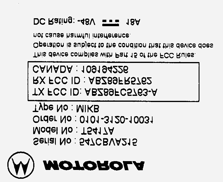
Click to zoom
Application Details
- Equipment Class
- TNB - Licensed Non-Broadcast Station Transmitter
- Date of Grant
- Nov 28, 2001
- Application Purpose
- Original Equipment
- Date of Application
- Nov 28, 2001
- Equipment Note
- Non-Broadcast Transmitter
- Frequency Range
- 851.00000000 - 870.00000000
- Company
- Motorola Solutions, Inc.
- Country
- United States
Documents & Files
Document Text
Text extracted from the exhibit documents filed with the FCC. Open a document above to read the original.
Users Manual
APPLICANT: MOTOROLA INC.EQUIPMENT TYPE: ABZ89FC5763-A EXHIBIT 8 INSTRUCTION MANUALS Due to the highly specialized application of this radio equipment, there is no ‘operational’ or ‘user’ manual. The instruction and service manual for this base radio are available on a compact disk (CD). The title of this CD is ‘EBTS and integrated Site Controller, SYSTEM MANUALS’, the part number is 98P80800A03-A (0/07/2001-UP). Pertinent sections of the manual have been extracted and included as part of this filing package in the form of an electronic pdf document. Upon request, published and/or printed manuals will be sent to the commission and/or telecommunication certification body (TCB). All of the descriptions and schematics included in this filing package are current as of the submission date. APPLICANT: MOTOROLA INC.EQUIPMENT TYPE: ABZ89FC5763-A EXHIBIT 9 TUNE-UP PROCEDURE There is no field tune-up procedure. All adjustments are software controlled and are pre-set at the factory. Certain station operating parameters can be changed via man-machine interface (MMI) commands, within predetermined limits. Examples include transmit / receiver operating frequencies and power level. 68P80801E35-A ECCN 5E992 Global Telecommunications Solutions Sector ENHANCED BASE TRANSCEIVER SYSTEM (EBTS) VOLUME 1 OF 3 SYSTEM INSTALLATION AND TESTING © 2001 Motorola, Inc. All Rights Reserved Printed in U.S.A. FCC INTERFERENCE WARNING The FCC requires that manuals pertaining to Class A computing devices must contain warnings about possible interference with local residential radio and TV reception. This warning reads as follows: Note: This equipment has been tested and found to comply with the limits for a Class A digital device, pursuant to Part 15 of the FCC Rules. These limits are designed to provide reasonable protection against harmful interference when the equipment generates, uses, and can radiate radio frequency energy and, if not installed and used in accordance with the instruction manual, may cause harmful interference to radio communications. Operation of this equipment in a residential area is likely to cause harmful interference in which case the user will be required to correct the interference at his own expense. INDUSTRY OF CANADA NOTICE OF COMPLIANCE This Class A digital apparatus meets all requirements of the Canadian Interference-Causing Equipment Regulations. Cet appareil numérique de la classe A respecte toutes les exigences du Règlement sur le matériel brouilleur du Canada. COMMERCIAL WARRANTY (STANDARD) Motorola radio communications products (the “Product”) is warranted to be free from defects in material and workmanship for a period of ONE (1) YEAR (except for crystals and channel elements which are warranted for a period of ten (10 years) from the date of shipment. Parts including crystals and channel elements, will be replaced free of charge for the full warranty period but the labor to replace defective parts will only be provided for One Hundred-Twenty (120) days from the date of shipment. Thereafter purchaser must pay for the labor involved in repairing the Product or replacing the parts at the prevailing rates together with any transportation charges to or from the place where warranty service is provided. This express warranty is extended by Motorola, 1301 E. Algonquin Road, Schaumburg, Illinois 60196 to the original end use purchaser only, and only to those purchasing for purpose of leasing or solely for commercial, industrial, or governmental use. THIS WARRANTY IS GIVEN IN LIEU OF ALL OTHER WARRANTIES EXPRESS OR IMPLIED WHICH ARE SPECIFICALLY EXCLUDED, INCLUDING WARRANTIES OF MERCHANTABILITY OR FITNESS FOR A PARTICULAR PURPOSE. IN NO EVENT SHALL MOTOROLA BE LIABLE FOR INCIDENTAL OR CONSEQUENTIAL DAMAGES TO THE FULL EXTENT SUCH MAY BE DISCLAIMED BY LAW. In the event of a defect, malfunction or failure to conform to specifications established by Motorola, or if appropriate to specifications accepted by Motorola in writing, during the period shown, Motorola, at its option, will either repair or replace the product or refund the purchase price thereof. Repair at Motorola's option, may include the replacement of parts or boards with functionally equivalent reconditioned or new parts or boards. Replaced parts or boards are warranted for the balance of the original applicable warranty period. All replaced parts or product shall become the property of Motorola. This express commercial warranty is extended by Motorola to the original end user purchaser or lessee only and is not assignable or transferable to any other party. This is the complete warranty for the Product manufactured by Motorola. Motorola assume no obligations or liability for additions or modifications to this warranty unless made in writing and signed by an officer of Motorola. Unless made in a separate agreement between Motorola and the original end user purchaser, Motorola does not warrant the installation, maintenance or service of the Products. Motorola cannot be responsible in any way for any ancillary equipment not furnished by Motorola which is attached to or used in connection with the Product, or for operation of the Product with any ancillary equipment, and all such equipment is expressly excluded from this warranty. Because each system which may use Product is unique, Motorola disclaims liability for range, coverage, or operation of the system as a whole under this warranty. This warranty does not cover: a) Defects or damage resulting from use of the Product in other than its normal and customary manner. b) Defects or damage from misuse, accident, water or neglect c) Defects or damage from improper testing, operation, maintenance installation, alteration, modification, or adjusting. d) Breakage or damage to antennas unless caused directly by defects in material workmanship. e) A Product subjected to unauthorized Product modifications, disassemblies or repairs (including without limitation, the addition to the Product of…
Text truncated - open the document above for the full version.
Cover Letter(s)
FCC ID: ABZ89FC5763-ANovember 19, 2001 Request for Confidentiality In accordance with 47 C.F.R. Section 0.459, we, Motorola Inc., hereby request confidentiality for the block diagrams, schematics, product descriptions, and circuit descriptions presented in Exhibit B. In support of the Request for Confidentiality, the following is stated: Enclosed within this application is technical information, which we deem to be trade secrets and proprietary. If made public, the information might be used to our disadvantage. To assist in assuring that we receive the full value of our product and protect its competitive posture, we respectfully request this grant of confidentiality. Motorola, Inc.
External Photos
APPLICANT: MOTOROLA INC.EQUIPMENT TYPE: ABZ89FC5763-A EXHIBIT 12 PHOTOGRAPHS -- INDEX EXHIBIT DESCRIPTION 12A-1Rear of Base Radio Including Location of the FCC ID Label 12A-2FCC Identification Label 12BBase Radio -- Front View 12CExciter Module 12D-1Power Amplifier Module, Heat Sink View 12D-2Power Amplifier Module, Top View, Shields Removed 12EPower Supply Module, Cover Removed 12FEnhanced Base Radio Control Module 12G-1Backplane Board, Front Side 12G-2Backplane Board, Back Side APPLICANT: MOTOROLA INC.EQUIPMENT TYPE: ABZ89FC5763-A EXHIBIT 12A-1 Rear of Base Radio Including Location of the FCC ID Label FCC Label APPLICANT: MOTOROLA INC.EQUIPMENT TYPE: ABZ89FC5763-A EXHIBIT 12A-2 FCC Identification Label APPLICANT: MOTOROLA INC.EQUIPMENT TYPE: ABZ89FC5763-A EXHIBIT 12B Base Radio -- Front View
ID Label/Location Info
APPLICANT: MOTOROLA INC.EQUIPMENT TYPE: ABZ89FC5763-A EXHIBIT 2 IDENTIFICATION LABEL LOCATION X See The Attached Photographs (EXHIBIT 12A-1, EXHIBIT 12A-2) X Back Of Radio Back Of Radio Under Belt Clip APPLICANT: MOTOROLA INC.EQUIPMENT TYPE: ABZ89FC5763-A EXHIBIT 12A-1 Rear of Base Radio Including Location of the FCC ID Label FCC Label APPLICANT: MOTOROLA INC.EQUIPMENT TYPE: ABZ89FC5763-A EXHIBIT 12A-2 FCC Identification Label
Internal Photos
APPLICANT: MOTOROLA INC.EQUIPMENT TYPE: ABZ89FC5763-A EXHIBIT 12C Exciter Module, Top Side APPLICANT: MOTOROLA INC.EQUIPMENT TYPE: ABZ89FC5763-A EXHIBIT 12D-1 Power Amplifier Module, Heat Sink View APPLICANT: MOTOROLA INC.EQUIPMENT TYPE: ABZ89FC5763-A EXHIBIT 12D-2 Power Amplifier Module, Top View, Shields Removed APPLICANT: MOTOROLA INC.EQUIPMENT TYPE: ABZ89FC5763-A EXHIBIT 12E Power Supply Module, Cover Removed APPLICANT: MOTOROLA INC.EQUIPMENT TYPE: ABZ89FC5763-A EXHIBIT 12F Enhanced Base Radio Control Module, Top Side APPLICANT: MOTOROLA INC.EQUIPMENT TYPE: ABZ89FC5763-A EXHIBIT 12G-1 Backplane Board, Front Side APPLICANT: MOTOROLA INC.EQUIPMENT TYPE: ABZ89FC5763-A EXHIBIT 12G-2 Backplane Board, Back Side
Parts List/Tune Up Info
APPLICANT: MOTOROLA INC.EQUIPMENT TYPE: ABZ89FC5763-A EXHIBIT 6 (Sheet 1 of 2) Function of RF Semiconductors and Other Active Devices SchematicDevice Circuit Operation Key Type Application Frequency BASE RADIO CONTROL MODULE Y3800Crystal OscillatorVoltage Controlled Crystal Oscillator16.8 MHz U3803MC145170Synthesizer IC5 / 16.8 MHz U3805MC74HC4066Analog Switch for Steering Line ControlDC U3807MAX999Comparator Center Slicer16.8 MHz Q3800MMBT3904LT1Single to Differential Amplifier2.1 MHz Q3801MMBT3904LT1Single to Differential Amplifier2.1 MHz Q3802MMBT3904LT1VCO Buffer Amplifier16.8 MHz U2400AMI5G3ASIC gate Array TISIC 22.1 MHz EXCITER MODULE Q3002MMBT3904Digital Data Driver4.8 MHz Q3003MMBT3904Digital Data Driver4.8 MHz U3000SN65176BDigital Data Driver4.8 MHz U3001SN65176BDigital Data Clock Driver4.8 MHz Q3000MMBT3904Digital Data Clock Driver4.8 MHz Q3001MMBT3904Digital Data Clock Driver4.8 MHz U5001M4A3_128Programmable Logic Array4.8 MHz U3401AD1859Digital To Analog Converter48 kHz U3402MC33072Baseband Filter12 kHz U3403MC33074ABaseband Filter12 kHz U3800XC390138LNODCT/Modulator/Demodulator851 - 870 MHz Q3901BFG135Buffer Amplifier851 - 870 MHz Q3906BFG135Buffer Amplifier 851 - 870 MHz Q3906BFG135Driver Amplifier851 - 870 MHz U3200MC145202Synthesizer941.3 - 960.3 MHz Q3201MMBR901Synthesizer Buffer941.3 - 960.3 MHz Q3200MMBT3904Synthesizer Reference Buffer2.4 MHz Q3700MMBR901Offset VCO90.3 MHz U3701MSA0386Offset VCO Buffer90.3 MHz U3702MSA0386Offset VCO Buffer90.3 MHz U3301NE68519VCO 941.3 - 960.3 MHz U3302MGA82563VCO Buffer941.3 - 960.3 MHz CR3520HSMS2812Mixer Diode851 - 870 MHz CR3521HSMS2812Mixer Diode851 - 870 MHz U3560INA02186Injection Amplifier851 - 870 MHz U3603MC332690RegulatorDC U3602MC78M05RegulatorDC U3600MC332690RegulatorDC
Parts List/Tune Up Info
APPLICANT: MOTOROLA INC.EQUIPMENT TYPE: ABZ89FC5763-A EXHIBIT 9 TUNE-UP PROCEDURE There is no field tune-up procedure. All adjustments are software controlled and are pre-set at the factory. Certain station operating parameters can be changed via man-machine interface (MMI) commands, within predetermined limits. Examples include transmit / receiver operating frequencies and power level.
RF Exposure Info
APPLICANT: MOTOROLA INC.EQUIPMENT TYPE: ABZ89FC5763-A EXHIBIT 4 DESCRIPTION 1.Single Channel -- Transmitter Technical Characteristics -- Pursuant 2.983 (d) A.RF Power OutputVariable from 5 Watts to 70 Watts (Average) B.Frequency Range851 MHz to 870 MHz C.Frequency Stability0.00001 % D.Emissions 17K7D7W E.Spurious EmissionsBetter than –60.5 dBC F.DC Voltage and Current into28.5 Volts the final RF amplifier stage/stages14.7 Amps maximum G.Maximum Power Rating420 Watts maximum 2.Transmitter Application A.Power Supply Available ( ) AC 120V 60 Hz ( ) AC 240V 60 Hz ( ) AC 120V 50 Hz ( ) AC 240V 50 Hz ( x ) DC Supply ±48 / 60 Volts DC B.Squelch Type Available ( ) Carrier Squelch( ) Tone Private Line ( ) Digital Private Line C.Microphone Available ( ) Handheld Conventional ( ) Handset D.Maximum Channel Capability All models are fully synthesized and capable of tuning 5 and 6.25 kHz increments to transmit channels within the range of 851 to 870 MHz. E.Housing Styles Available The transmitter is designed to be a rack mounted unit, as shown in the accompanying photos. F.Digital Modulation Techniques This transmitter is capable of digital modulation where the modulating signal is fed directly to the modulator. 3.Electro-Magnetic Exposure (EME) -- Pursuant 1.1307 This transmitter is intended for use at fixed base station sites only, and is not to be marketed for mobile use. As such, under Section 1.1307 of the FCC Rules, the transmitter is not currently subject to the Commission’s environmental rules pertaining to the routine evaluation for RF exposure prior to equipment authorization. 68P80801E35-A 9/1/200123 EBTS System Manual - Vol 1System Installation and Testing General Safety Information Human Exposure Compliance This equipment is designed to generate and radiate radio frequency (RF) energy by means of an external antenna. When terminated into a non-radiating RF load, the base station equipment is certified to comply with Federal Communications Commission (FCC) regulations pertaining to human exposure to RF radiation in accordance with the FCC Rules Part 1 section 1.1310 as published in title 47 code of federal regulations and procedures established in TIA/EIA TSB92, Report on EME Evaluation for RF Cabinet Emissions Under FCC MPE Guidelines, Compliance to FCC regulations of the final installation should be assessed and take into account site specific characteristics such as type and location of antennas, as well as site accessibility of occupational personnel (controlled environment) and the general public (uncontrolled environment). This equipment should only be installed and maintained by trained technicians. Licensees of the FCC using this equipment are responsible for insuring that its installation and operation comply with FCC regulations Part 1 section 1.1310 as published in title 47 code of federal regulations. Whether a given installation meets FCC limits for human exposure to radio frequency radiation may depend not only on this equipment but also on whether the “environments” being assessed are being affected by radio frequency fields from other equipment, the effects of which may add to the level of exposure. Accordingly, the overall exposure may be affected by radio frequency generating facilities that exist at the time the licensee’s equipment is being installed or even by equipment installed later. Therefore, the effects of any such facilities must be considered in site selection and in determining whether a particular installation meets the FCC requirements. FCC OET Bulletin 65 provides materials to assist in making determinations if a given facility is compliant with the human exposure to RF radiation limits. Determining the compliance of transmitter sites of various complexities may be accomplished by means of computational methods. For more complex sites direct measurement of power density may be more expedient. Additional information on the topic of electromagnetic exposure is contained in the Motorola Standards and Guidelines for Communications Sites publication. Persons responsible for installation of this equipment are urged to consult the listed reference material to assist in determining whether a given installation complies with the applicable limits. In general the following guidelines should be observed when working in or around radio transmitter sites: - All personnel should have electromagnetic energy awareness training. - All personnel entering the site must be authorized. - Obey all posted signs. - Assume all antennas are active. - Before working on antennas, notify owners and disable appropriate transmitters. - Maintain minimum 3 feet clearance from all antennas. - Do not stop in front of antennas. - Use personal RF monitors while working near antennas. - Never operate transmitters without shields during normal operation. - Do not operate base station antennas in equipment rooms. 2468P80801E35-A 9/1/2001 System Installation and TestingEBTS System Manual - Vol 1 General Safety Information For installations outside of the U.S., consult with the applicable governing body and standards for RF energy human exposure requirements and take necessary steps for compliance with local regulations. References: TIA/EIA TSB92 “Report on EME Evaluation for RF Cabinet Emissions Under FCC MPE Guidelines”, Global Engineering Documents: http://globl.ihs.com/ FCC OET Bulletin 65 “Evaluating Compliance with FCC Guidelines for Human Exposure to Radiofrequency Electromagnetic Fields”; http://www.fcc.gov/oet/ rfsaftey/ Motorola Standards and Guidelines for Communications Sites, Motorola manual 68P81089E50 IEEE Recommended Practice for the Measure of Potentially Hazardous Electromagnetic Fields-- RF and Microwave, IEEE Std. C95.3-1991, Publication Sales, 445 Hoes Lane, P.O. Box 1331, Piscattaway, NJ 08855-1331 IEEE Standard for Safety Levels with Respect to Human Exposure to Radio Frequency Electromagnetic Fields, 3 kHz to 300 Iscattaway, NY 08855-1331GHz, IEEE C95.1-1991, Publication Sal…
Text truncated - open the document above for the full version.
Test Report
APPLICANT: MOTOROLA INC.EQUIPMENT TYPE: ABZ89FC5763-A EXHIBIT 1 STATEMENT OF CERTIFICATION The technical data supplied with this application, having been taken under my supervision is hereby duly certified. The following is a statement of my qualifications: College Degree:BSEE, Valparaiso University, Valparaiso, Indiana, USA MSEE, Illinois Institute of Technology, Chicago, Illinois, USA __19___ years of Design and Development experience in the field of two-way radio communication. NAME: Ken Weiss SIGNATURE: ___________________________ DATE: November 19, 2001 POSITION: Lead Electrical Engineer I hereby certify that the above application was prepared under my direction and that to the best of my knowledge and belief, the facts set forth in the application and accompanying technical data are true and correct: NAME: Steve Noskowicz SIGNATURE: ___________________________ DATE: November 19, 2001 POSITION: Engineering Manager APPLICANT: MOTOROLA INC.EQUIPMENT TYPE: ABZ89FC5763-A EXHIBIT 11 SUBMITTED MEASURED DATA -- INDEX EXHIBIT DESCRIPTION 11ARF Output-Data 11BOccupied Bandwidth - Power Output at 70 Watts 11CConducted Spurious Emissions: Setup, Specifications, and Index 11C-1Conducted Spurious Emissions, Harmonics, Power Output at 70 Watts 11C-2Conducted Spurious Emissions, Harmonics, Power Output at 5 Watts 11C-3Conducted Spurious Emissions, Close-In, Power Output at 70 Watts 11DRadiated Spurious Emissions: Setup, Specifications, and Index 11D-1Radiated Spurious Emissions, Power Output at 70 Watts 11D-2Radiated Spurious Emissions, Power Output at 5 Watts 11EFrequency Stability: Setup, Specifications, and Index 11E-1Frequency Stability Vs Temperature 11E-2Frequency Stability Vs Voltage APPLICANT: MOTOROLA INC.EQUIPMENT TYPE: ABZ89FC5763-A EXHIBIT 11A RF POWER OUTPUT DATA The RF power output was measured with the indicated voltage applied to and current into the final RF amplifying device. The DC current indicated is the total for the final RF amplifier stage, consisting of six parallel modules, or twelve parallel power transistors. Measured RF output70Watts, Average DC Voltage28.5Volts DC Current14.7Amperes Input power for final RF amplifying device(s)420Watts Primary Supply Voltage48Volts DC Minimum Measured RF output5Watts, Average Normal DC Voltage28.5Volts Normal DC Current2.5Amperes Input power for final RF amplifying device(s)70Watts Primary Supply Voltage48Volts DC APPLICANT: MOTOROLA INC.EQUIPMENT TYPE: ABZ89FC5763-A EXHIBIT 11B (Sheet 1 of 2) OCCUPIED BANDWIDTH Modulation Type:Quad-QAM – 64 kbps Random Data Per Channel – Single Carrier Emission Designator:17K7D7W Channelization:25 kHz per channel Power Setting:70-Watts Average SPECIFICATION REQUIREMENT: § 90.691 Emission Mask Requirements for EA-Based Systems: (a)Out of band emission requirements apply only to the ‘outer’ channels included in an EA license and to spectrum adjacent to interior channels used by incumbent licensees. The emission limits are as follows: (1)For any frequency removed from the EA licensee’s frequency block by up to and including 37.5 kHz, the power of any emission shall be attenuated below the transmitter power (P), in Watts, by at least 116*log 10 (F/6.1) dB or 50 plus 10 log 10 (P) dB or 80 dB, whichever is the lesser attenuation, where F is the frequency removed from the center of the outer channel in the block, in kiloHertz, and where F is greater than 12.5 kHz. (2)For any frequency removed from the EA licensee’s frequency block by greater than 37.5 kHz, the power of any emission shall be attenuated below the transmitter power (P), in Watts, by at least 43 plus 10 log 10 (P) dB or 80 dB, whichever is the lesser attenuation, where F is the frequency removed from the center of the outer channel in the block, in kiloHertz, and where F is greater than 37.5 kHz. (b) When an emission outside of the authorized bandwidth causes harmful interference, the Commission may, at its discretion, require greater attenuation than specified in this section. Necessary Bandwidth Calculation: The necessary bandwidth of the modulation signal is not calculable per the formulas defined in 47 CFR 2.202 (b). Specifically, although the modulation for this emission is a composite modulation, the equations given in the composite tables in 2.202 are not applicable since none of them adequately approximate the form of digital modulation used. The necessary bandwidth of 17.7 kHz per carrier is based upon a 99% power measurement of the transmitter spectrum, per 2.202 (a). Measurement Procedure and Instrument Settings: Reference Calibration Analyzer Settings: Horizontal:12.5 kHz per DivisionResolution Bandwidth:300 kHz Vertical:10 dB per DivisionVideo Bandwidth:300 kHz Sweep Time:75 Seconds (<2000 Hz / Second)Span:125 kHz Detector Mode:Positive Peak Emission Measurement Analyzer Settings: Horizontal:12.5 kHz per DivisionResolution Bandwidth:300 Hz Vertical:10 dB per DivisionVideo Bandwidth:3 kHz Sweep Time:75 Seconds (<2000 Hz / Second)Span:125 kHz Detector Mode:Positive Peak Test Procedure: 1)Adjust the spectrum analyzer per the values specified in the Reference Calibration Analyzer Settings. 2)Modulate the transmitter with the appropriate signaling pattern, (psuedorandom data) and key the transmitter at the full carrier power rating. Use the analyzer controls to set this signal to the full-scale reference line. Allow the analyzer to sweep fully and store the sweep. 3)Adjust the analyzer per the Emission Measurement Analyzer Settings. 4)Allow the analyzer to sweep, and record the resultant emission levels. 5) Plot the resulting analyzer trace and the emission mask limit, add text and labeling as appropriate. APPLICANT: MOTOROLA, INC. EXHIBIT 11B (Sheet 2 of 2) EQUIPMENT TYPE: ABZ89FC5763-A Occupied Bandwidth -- EBRC / LNODCT - 70 Watts -100 -90 -80 -70 -60 -50 -40 -30 -20 -10 0 -62.5-50-37.5-25-12.5012.52537.55062.5 CENTER 860.0125 MHz RES BW 30 kHz RES BW 300 Hz EA Mask - 70 W 10 dB/ POS PK RES BW 300 Hz REF 7.6 dBmATTEN 20 dB VID BW 10…
Text truncated - open the document above for the full version.
Contact Information
Applicant
Matthew Nawrocki
Non-Technical Contact
Motorola, Inc.Steven Noskowicz
1 847 632 5075
Test Firm
Motorola, Inc.William Bily
847-576-2238Fax: 847-538-3905
Technical Specifications
| # | Rule Parts | Frequency Range | Power Output | Emission | Tolerance |
|---|---|---|---|---|---|
| 1 | 90 | 851 MHz - 870 MHz | 70 W | 17K7D7W | 1.0000000000 ppm |
Other Applications from Motorola Solutions, Inc.

ABZ89FT4940
Aug 06, 2026Non Broadcast Transmitter
Equipment Class
TNB - Licensed Non-Broadcast Station TransmitterABZ89FT4950
Jun 25, 2026Non-Broadcast Transmitter
Equipment Class
TNB - Licensed Non-Broadcast Station TransmitterABZ89FT5901
Jun 20, 2024Non Broadcast Transmitter
Equipment Class
TNB - Licensed Non-Broadcast Station Transmitter
ABZ99FT5101B
May 02, 2023Non Broadcast Transmitter
Equipment Class
PCB - PCS Licensed Transmitter
ABZ99FT3095B
Mar 26, 2023Non Broadcast Transmitter
Equipment Class
TNB - Licensed Non-Broadcast Station Transmitter