ABZ89FC5794Enhanced Base Transceiver System (EBTS)
Motorola Solutions, Inc.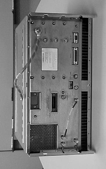
Click to zoom
Application Details
- Equipment Class
- TNB - Licensed Non-Broadcast Station Transmitter
- Date of Grant
- Jan 24, 2001
- Application Purpose
- Original Equipment
- Date of Application
- Jan 24, 2001
- Equipment Note
- Enhanced Base Transceiver System (EBTS)
- Frequency Range
- 851.00000000 - 866.00000000
- Company
- Motorola Solutions, Inc.
- Country
- United States
Documents & Files
Document Text
Text extracted from the exhibit documents filed with the FCC. Open a document above to read the original.
Users Manual
APPLICANT: MOTOROLA INC.EQUIPMENT TYPE: ABZ89FC5794 EXHIBIT 8 INSTRUCTION MANUALS The instruction and service manual for this base radio are not published at this time. However, draft copy of the manual is available and has been included as part of the filing package in the form of an electronic pdf document. Upon request, published and/or printed manuals will be sent to the commission and/or telecommunication certification body (TCB) as soon as they become available. All of the descriptions and schematics included this filing package are up to date. APPLICANT: MOTOROLA INC.EQUIPMENT TYPE: ABZ89FC5794 EXHIBIT 9 TUNE-UP PROCEDURE There is no field tune-up procedure. All adjustments are software controlled and are pre-set at the factory. Certain station operating parameters can be changed via man-machine interface (MMI) commands, within predetermined limits. Examples include transmit / receiver operating frequencies and power level. 68P81099E10-D ECCN 5E992 Network Solutions Sector ENHANCED BASE TRANSCEIVER SYSTEM (EBTS) VOLUME 2 OF 3 BASE RADIOS © 2000 Motorola, Inc. All Rights Reserved Printed in U.S.A. FCC INTERFERENCE WARNING The FCC requires that manuals pertaining to Class A computing devices must contain warnings about possible interference with local residential radio and TV reception. This warning reads as follows: Note: This equipment has been tested and found to comply with the limits for a Class A digital device, pursuant to Part 15 of the FCC Rules. These limits are designed to provide reasonable protection against harmful interference when the equipment generates, uses, and can radiate radio frequency energy and, if not installed and used in accordance with the instruction manual, may cause harmful interference to radio communications. Operation of this equipment in a residential area is likely to cause harmful interference in which case the user will be required to correct the interference at his own expense. INDUSTRY OF CANADA NOTICE OF COMPLIANCE This Class A digital apparatus meets all requirements of the Canadian Interference-Causing Equipment Regulations. Cet appareil numérique de la classe A respecte toutes les exigences du Règlement sur le matériel brouilleur du Canada. COMMERCIAL WARRANTY (STANDARD) Motorola radio communications products (the “Product”) is warranted to be free from defects in material and workmanship for a period of ONE (1) YEAR (except for crystals and channel elements which are warranted for a period of ten (10 years) from the date of shipment. Parts including crystals and channel elements, will be replaced free of charge for the full warranty period but the labor to replace defective parts will only be provided for One Hundred-Twenty (120) days from the date of shipment. Thereafter purchaser must pay for the labor involved in repairing the Product or replacing the parts at the prevailing rates together with any transportation charges to or from the place where warranty service is provided. This express warranty is extended by Motorola, 1301 E. Algonquin Road, Schaumburg, Illinois 60196 to the original end use purchaser only, and only to those purchasing for purpose of leasing or solely for commercial, industrial, or governmental use. THIS WARRANTY IS GIVEN IN LIEU OF ALL OTHER WARRANTIES EXPRESS OR IMPLIED WHICH ARE SPECIFICALLY EXCLUDED, INCLUDING WARRANTIES OF MERCHANTABILITY OR FITNESS FOR A PARTICULAR PURPOSE. IN NO EVENT SHALL MOTOROLA BE LIABLE FOR INCIDENTAL OR CONSEQUENTIAL DAMAGES TO THE FULL EXTENT SUCH MAY BE DISCLAIMED BY LAW. In the event of a defect, malfunction or failure to conform to specifications established by Motorola, or if appropriate to specifications accepted by Motorola in writing, during the period shown, Motorola, at its option, will either repair or replace the product or refund the purchase price thereof. Repair at Motorola's option, may include the replacement of parts or boards with functionally equivalent reconditioned or new parts or boards. Replaced parts or boards are warranted for the balance of the original applicable warranty period. All replaced parts or product shall become the property of Motorola. This express commercial warranty is extended by Motorola to the original end user purchaser or lessee only and is not assignable or transferable to any other party. This is the complete warranty for the Product manufactured by Motorola. Motorola assume no obligations or liability for additions or modifications to this warranty unless made in writing and signed by an officer of Motorola. Unless made in a separate agreement between Motorola and the original end user purchaser, Motorola does not warrant the installation, maintenance or service of the Products. Motorola cannot be responsible in any way for any ancillary equipment not furnished by Motorola which is attached to or used in connection with the Product, or for operation of the Product with any ancillary equipment, and all such equipment is expressly excluded from this warranty. Because each system which may use Product is unique, Motorola disclaims liability for range, coverage, or operation of the system as a whole under this warranty. This warranty does not cover: a) Defects or damage resulting from use of the Product in other than its normal and customary manner. b) Defects or damage from misuse, accident, water or neglect c) Defects or damage from improper testing, operation, maintenance installation, alteration, modification, or adjusting. d) Breakage or damage to antennas unless caused directly by defects in material workmanship. e) A Product subjected to unauthorized Product modifications, disassemblies or repairs (including without limitation, the addition to the Product of non-Motorola supplied equipment) which adversely affect performance of the Product or interfere with Motorola's normal warranty inspection and testing of the Product to verify any warranty claim. f) Product which has had the serial number removed or made illegible. g) A Produc…
Text truncated - open the document above for the full version.
Cover Letter(s)
FCC ID: ABZ89FC5794January 15, 2001 Request for Confidentiality In accordance with 47 C.F.R. Section 0.459, we, Motorola Inc., hereby request confidentiality for the block diagrams, schematics, product descriptions, and circuit descriptions presented in Exhibit B. In support of the Request for Confidentiality, the following is stated: Enclosed within this application is technical information, which we deem to be trade secrets and proprietary. If made public, the information might be used to our disadvantage. To assist in assuring that we receive the full value of our product and protect its competitive posture, we respectfully request this grant of confidentiality. Motorola, Inc.
Cover Letter(s)
To:Commission Reviewer From:Richard King Certification Department Coordinator Elite Electronic Engineering RE:FCC ID: ABZ89FC5794 Applicant:Motorola, Inc. Corr. Ref. #: 731 Confirm. #: Date: In reference to a request for certification from Motorola, Inc of a Enhanced Base Transciever System (EBTS). Elite performed a certification of the above referenced product manufactured by Motorola, Inc. Deficiencies were discovered during the certification process. The noted deficiencies were addressed in correspondence between the appropriate test facilities and Elite Electronic Engineering. The correspondence is indicated below. Questions from Elite dated January 18, 2001. We have reviewed the Enhanced Base Transceiver System (EBTS), which was presented for certification. Upon review of the Enhanced Base Transceiver System (EBTS) it was determined that additional information is required before the certification can continue. Please address the following issues: 1. Exhibit E - 2.1049 Occupied Bandwidth. The mask used for the occupied bandwidth plot is based on the 10.5 watt per carrier level. The mask calculation should be based on the 42-watt composite carrier. See attachment labeled “occBWplot.pdf” for a corrected mask limit. 2. The emission designator per 2.201 indicated in the application should be 92K7D7W for the 4- channel function and 17K7DXW for the single channel function. Please justify the use of 92K7W7W for the 4-channel and 17K7W7W for the single channel function. Response to Elite’s questions dated January 18, 2001. Thank you for your quick review of our filing package, ABZ89FC5794. We have provided the following in response to your correspondence dated January 18, 2001. Q1.Exhibit E - 2.1049 Occupied Bandwidth. The mask used for the occupied bandwidth plot is based on the 10.5 watt per carrier level. The mask calculation should be based on the 42-watt composite carrier. See attachment labeled “occBWplot.pdf” for a corrected mask limit. A1.As we discussed on the phone earlier, the occupied bandwidth data for quad carrier was remeasured using the 42 Watt / Quad carrier reference. I have sent via FAX a copy of the resulting spectrum plot with the revised mask limits drawn in. I will have the revised exhibit available probably on Monday and will send it to you via email. Q2.The emission designator per 2.201 indicated in the application should be 92K7D7W for the 4- channel function and 17K7DXW for the single channel function. Please justify the use of 92K7W7W for the 4-channel and 17K7W7W for the single channel function. A2.The ‘D7W’ designator (emission in w hich the main carrier is amplitude and angle modulated...) is acceptable and is in fact probably more appropriate than ‘W7W’. The ‘W7W’ had been requested simply to be consistent with some of our previous radios. I will revise all exhibits that change as a result of the different emission designators, and will send the revised exhibits to you by Monday. In addition, we discussed whether the single and quad modes for this radio would ‘bracket’ the performance of the radio in two and three carrier modes. The radio is actually capable of operating with 1, 2, 3, or 4 carriers active, as shown in the diagram below. The number of channels in a given unit are not dynamically changed – for example on a per call basis. Rather, the number of channels are set up per the frequency planning / customer channel allocation. This may change for a given radio, but very infrequently, and only as a result of operation and maintenance functions of the system. 1 Sub-carrier 2 Sub-carriers 3 Sub-carriers4 Sub-carriers Carrier feedthrough Sub-Carrier Configurations Measurements show that the occupied bandwidth of a single carrier is 17.7 kHz. Accordingly, the necessary bandwidth (NBW) for the single carrier configuration would be 17.7 kHz and the 2-4 carrier configurations NBW would be increased by 25 kHz for each additional carrier. In addition, the maximum power of the radio for the various modes varies slightly due to the peak to average requirements of the composite signal. The carrier configuration vs. NBW and power rating is summarized below: Number of Carriers Emission Designator Power Rating (Watts) 1 17K7D7W 52 2 42K7D7W 52 3 67K7D7W 48 4 92K7D7W 42 All two and three carrier performance pertinent to the measurements included in the filing package is bracketed by the performance of the single and quad configurations shown in the package. Should you feel it necessary to show the additional two-channel and three-channel modes in the package, we would welcome your suggestions as how best to do that. Upon further consideration, we feel the resulting grant should show the four emission designators that are noted in the table above. Rick King Elite Electronic Engineering
External Photos
APPLICANT: MOTOROLA INC.EQUIPMENT TYPE: ABZ89FC5794 EXHIBIT 12A-1 Rear of Quad Base Radio Including Location of the FCC ID Label APPLICANT: MOTOROLA INC.EQUIPMENT TYPE: ABZ89FC5794 EXHIBIT 12B Quad Base Radio -- Front View
ID Label/Location Info
APPLICANT: MOTOROLA INC.EQUIPMENT TYPE: ABZ89FC5794 EXHIBIT 2 IDENTIFICATION LABEL LOCATION X See The Attached Photographs (EXHIBIT 12A-1, EXHIBIT 12A-2) X Back Of Radio Back Of Radio Under Belt Clip APPLICANT: MOTOROLA INC.EQUIPMENT TYPE: ABZ89FC5794 EXHIBIT 12A-1 Rear of Quad Base Radio Including Location of the FCC ID Label APPLICANT: MOTOROLA INC.EQUIPMENT TYPE: ABZ89FC5794 EXHIBIT 12A-2 FCC Identification Label
Internal Photos
APPLICANT: MOTOROLA INC.EQUIPMENT TYPE: ABZ89FC5794 EXHIBIT 12 PHOTOGRAPHS -- INDEX EXHIBIT DESCRIPTION 12A-1Rear of Quad Base Radio Including Location of the FCC ID Label 12A-2FCC Identification Label 12BQuad Base Radio -- Front View 12CExciter / Base Radio Control Module 12DPower Amplifier Module, Top View, Shields Removed 12EPower Supply Module, Cover Removed 12G-1Backplane Board, Front Side 12G-2Backplane Board, Back Side APPLICANT: MOTOROLA INC.EQUIPMENT TYPE: ABZ89FC5794 EXHIBIT 12C Exciter / Base Radio Control Module, Top Side APPLICANT: MOTOROLA INC.EQUIPMENT TYPE: ABZ89FC5794 EXHIBIT 12E Power Amplifier Module, Top View, Shields Removed APPLICANT: MOTOROLA INC.EQUIPMENT TYPE: ABZ89FC5794 EXHIBIT 12E Power Supply Module, Cover Removed APPLICANT: MOTOROLA INC.EQUIPMENT TYPE: ABZ89FC5794 EXHIBIT 12G-1 Backplane Board, Front Side APPLICANT: MOTOROLA INC.EQUIPMENT TYPE: ABZ89FC5794 EXHIBIT 12G-2 Backplane Board, Back Side
Parts List/Tune Up Info
APPLICANT: MOTOROLA INC.EQUIPMENT TYPE: ABZ89FC5794 EXHIBIT 9 TUNE-UP PROCEDURE There is no field tune-up procedure. All adjustments are software controlled and are pre-set at the factory. Certain station operating parameters can be changed via man-machine interface (MMI) commands, within predetermined limits. Examples include transmit / receiver operating frequencies and power level.
Test Report
APPLICANT: MOTOROLA INC.EQUIPMENT TYPE: ABZ89FC5794 LIST OF EXHIBITS (Sheet 1 of 2) LIST OF EXHIBITS FCC EXHIBIT DESCRIPTION REFERENCE 1Certification of Data2.911 2Identification label information2.1033-(c)(11) 3General Information 1. Production Plans 2. Application References2.1061 3. Data Submittal Procedure 4Description 1. Technical Characteristics2.1033-(c)(4,5,6,7,8) 2. Application 3. Electro-Magnetic Exposure (EME)1.1307 5Transmit Frequency Programmability90.203 6Function of Semiconductor or other active devices2.1033-(c)(10) 7Circuit Diagrams2.1033-(c)(10) 7AReference Oscillator Schematic 7BExciter / Base Radio Control (ExBRC) Module Schematic (10 Sheets) 7C1st Voltage Controlled Oscillator Schematic 7D2nd Voltage Controlled Oscillator Schematic 7EFrequency Synthesizer Schematic 7FPower Amplifier Schematic (8 Sheets) 8Instruction Manuals2.1033-(c)(3) 9Tune-up Procedure2.1033-(c)(9) 10Circuit Description2.1033-(c)(10) 10AMeans of Frequency Stabilization2.1033-(c)(10) 10BMeans of Attenuating Spurious and Harmonic Emissions2.1033-(c)(10) 10CMeans of Controlling Modulation2.1033-(c)(10) 10DMeans of Digital Modulation2.1033-(c)(13) 10EMeans of Limiting Power2.1033-(c)(10) APPLICANT: MOTOROLA INC.EQUIPMENT TYPE: ABZ89FC5794 LIST OF EXHIBITS (Sheet 2 of 2) LIST OF EXHIBITS (Continued) EXHIBIT DESCRIPTION REFERENCE 11Measured Data - Index2.1033-(c)(14) 11ARF Output-Data2.1046-(a) 11BOccupied Bandwidth2.1049 11CConducted Spurious Emissions2.1051 11DRadiated Spurious Emissions2.1053 11EFrequency Stability (Temperature & Supply Voltage)2.1055 12Photographs -- Index2.1033-(c)(12) 12AFCC Identification Label2.1033-(c)(11) 12BQuad Base Radio -- Front View 12CExciter / Base Radio Control Module 12DPower Amplifier Module 12EPower Supply Module 12GBackplane Board 13Test Equipment Used2.1075 APPLICANT: MOTOROLA INC.EQUIPMENT TYPE: ABZ89FC5794 EXHIBIT 1 STATEMENT OF CERTIFICATION The technical data supplied with this application, having been taken under my supervision is hereby duly certified. The following is a statement of my qualifications: College Degree:BSEE, Valparaiso University, Valparaiso, Indiana, USA MSEE, Illinois Institute of Technology, Chicago, Illinois, USA __18___ years of Design and Development experience in the field of two-way radio communication. NAME: Ken Weiss SIGNATURE: ___________________________ DATE: January 15, 2001 POSITION: Lead Electrical Engineer I hereby certify that the above application was prepared under my direction and that to the best of my knowledge and belief, the facts set forth in the application and accompanying technical data are true and correct: NAME: Ron Wegner SIGNATURE: ___________________________ DATE: January 15, 2001 POSITION: Engineering Manager APPLICANT: MOTOROLA INC.EQUIPMENT TYPE: ABZ89FC5794 EXHIBIT 11 SUBMITTED MEASURED DATA -- INDEX EXHIBIT DESCRIPTION 11ARF Output-Data 11BOccupied Bandwidth 11B-1Single Carrier – Occupied Bandwidth, Power Output at 52 Watts 11B-2Dual Carrier – Occupied Bandwidth, Power Output at 52 Watts 11B-3Triple Carrier – Occupied Bandwidth, Power Output at 48 Watts 11B-4Quad Carrier – Occupied Bandwidth, Power Output at 42 Watts 11CConducted Spurious Emissions: Setup, Specifications, and Index 11C-1Quad Carrier - Conducted Spurious Emissions, Harmonics, Power Output at 42 Watts 11C-2Quad Carrier - Conducted Spurious Emissions, Harmonics, Power Output at 5 Watts 11C-3Single Carrier - Conducted Spurious Emissions, Harmonics, Power Output at 52 Watts 11C-4Single Carrier - Conducted Spurious Emissions, Harmonics, Power Output at 5 Watts 11C-5Quad Carrier - Conducted Spurious Emissions, Close-In, Power Output at 42 Watts 11C-6Single Carrier - Conducted Spurious Emissions, Close-In, Power Output at 52 Watts 11DRadiated Spurious Emissions: Setup, Specifications, and Index 11D-1Quad Carrier - Radiated Spurious Emissions, Power Output at 42 Watts 11D-2Quad Carrier - Radiated Spurious Emissions, Power Output at 5 Watts 11D-3Single Carrier - Radiated Spurious Emissions, Power Output at 52 Watts 11D-4Single Carrier - Radiated Spurious Emissions, Power Output at 5 Watts 11EFrequency Stability: Setup, Specifications, and Index 11E-1Frequency Stability Vs Temperature 11E-2Frequency Stability Vs Voltage APPLICANT: MOTOROLA INC.EQUIPMENT TYPE: ABZ89FC5794 EXHIBIT 11A RF POWER OUTPUT DATA The RF power output was measured with the indicated voltage applied to and current into the final RF amplifying device. The DC current indicated is the total for the final RF amplifier stage, consisting of six parallel modules, or twelve parallel power transistors. Quad Carrier Mode: Measured RF output42Watts, Average DC Voltage28.3Volts DC Current10.7Amperes Input power for final RF amplifying device(s)303Watts Primary Supply Voltage48Volts DC Minimum Measured RF output5Watts, Average Normal DC Voltage28.3Volts Normal DC Current4.9Amperes Input power for final RF amplifying device(s)139Watts Primary Supply Voltage48Volts DC Single Carrier Mode: Measured RF output52Watts, Average Normal DC Voltage28.3Volts Normal DC Current12.0Amperes Input power for final RF amplifying device(s)340Watts Primary Supply Voltage48Volts DC Minimum Measured RF output5Watts, Average Normal DC Voltage28.3Volts Normal DC Current4.9Amperes Input power for final RF amplifying device(s)139Watts Primary Supply Voltage48Volts DC APPLICANT: MOTOROLA INC.EQUIPMENT TYPE: ABZ89FC5794 EXHIBIT 11B-1 (Sheet 1 of 2) OCCUPIED BANDWIDTH – SINGLE CARRIER Modulation Type:Quad-QAM – 64 kbps Random Data Per Channel – Single Carrier Emission Designator:17K7D7W Channelization:25 kHz per channel Power Setting:52 Watts Average SPECIFICATION REQUIREMENT: § 90.691 Emission Mask Requirements for EA-Based Systems: (a)Out of band emission requirements apply only to the ‘outer’ channels included in an EA license and to spectrum adjacent to interior channels used by incumbent licensees. The emission limits are as follows: (1)For any frequency removed from the EA licensee’s frequency block by up to and in…
Text truncated - open the document above for the full version.
Contact Information
Applicant
Matthew Nawrocki
Non-Technical Contact
Motorola, Inc.Ronald A Wegner
847 576-5711
Test Firm
Motorola, Inc.William Bily
847-576-2238Fax: 847-538-3905
Technical Specifications
| # | Rule Parts | Frequency Range | Power Output | Emission | Tolerance |
|---|---|---|---|---|---|
| 4 | 9 | 851 MHz - 866 MHz | 52 W | 17K7D7W | 1 ppm |
Other Applications from Motorola Solutions, Inc.

ABZ89FT4940
Aug 06, 2026Non Broadcast Transmitter
Equipment Class
TNB - Licensed Non-Broadcast Station TransmitterABZ89FT4950
Jun 25, 2026Non-Broadcast Transmitter
Equipment Class
TNB - Licensed Non-Broadcast Station TransmitterABZ89FT5901
Jun 20, 2024Non Broadcast Transmitter
Equipment Class
TNB - Licensed Non-Broadcast Station Transmitter
ABZ99FT5101B
May 02, 2023Non Broadcast Transmitter
Equipment Class
PCB - PCS Licensed Transmitter
ABZ99FT3095B
Mar 26, 2023Non Broadcast Transmitter
Equipment Class
TNB - Licensed Non-Broadcast Station Transmitter